1
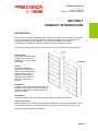
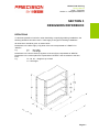
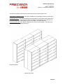
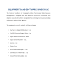
Ultima Shelving
CI-80 Shelving System
Design Manual
Blank
Ultima Shelving
Design Manual
This manual remains the sole property of Dexion Commercial. It must not be copied without
prior written consent and must be returned upon request. The information contained within
this manual is to be regarded as confidential and must not be disclosed to any third party.
Whilst the utmost care is taken to ensure the accuracy of the data and design details shown
within, Dexion cannot, under any circumstances, be held liable for any injuries, expenses or
loss which may, in any degree, be attributed to the use or adoption of such data and design
details.
Any modification, repair, or alteration of the products described herein by a third party without
written approval voids Dexion’s warranty obligations.
© Copyright:
Dexion Commercial
25 Peterkin Street
Wingate
Lower Hutt
Wellington 5045
Phone: + 64 4 920 5400
Fax:
+ 64 4 920 5402
Date of Issue: June 2013
Blank
Ultima Shelving
Design Manual
Issue/
Amendment
Issue 1
Date Issued
Feb 2009
Description
Product Launch (NZ)
Notes
Blank
Ultima CI-80 shelving
Design Manual
Issue 1 Feb 2009
Ultima Shelving
Table of Contents
SECTION 1 PRODUCT INTRODUCTION .................................................................................... 1
INTRODUCTION......................................................................................................................... 1
PARAMETERS OF THE SYSTEM ............................................................................................. 2
SECTION 2 COMPONENT DESCRIPTIONS ............................................................................... 1
FRAME PANELS ........................................................................................................................ 1
BACK PANELS ........................................................................................................................... 2
BACK BRACING ......................................................................................................................... 3
SHELF......................................................................................................................................... 4
SHELF CLIPS ............................................................................................................................. 5
SHELF STIFFENER ................................................................................................................... 5
KICKPLATE ................................................................................................................................ 6
BASEPLATE ............................................................................................................................... 7
LEVELLING PLATE .................................................................................................................... 7
FASTENERS............................................................................................................................... 8
M6 X 10 COMB SCREW & NUT ZP ........................................................................................ 8
M6 X 16 SET SCREW AND M6 NYLOC NUT ......................................................................... 8
SCREW 8G X 3/8 (10MM) PAN HD SELF TAPPING.............................................................. 9
NUT - 8G ‘U’ ............................................................................................................................. 9
FLOOR FIXING ........................................................................................................................ 9
REAR COVER .......................................................................................................................... 10
FINISHING PANEL ................................................................................................................... 11
SECTION 3 DESIGNERS REFERENCE ...................................................................................... 1
DEFINITIONS ............................................................................................................................. 1
GENERAL LAYOUT ................................................................................................................... 3
GENERAL DESIGN RULES AND RECOMMENDATIONS........................................................ 4
ALLOWANCE FOR CREEP ....................................................................................................... 4
LEFT TO RIGHT....................................................................................................................... 4
FRONT TO BACK .................................................................................................................... 4
INSTALLATION PLANNING ....................................................................................................... 5
GENERAL ................................................................................................................................ 5
SHELF LAYOUT PLAN ............................................................................................................ 5
PLAN BAY LAYOUTS .............................................................................................................. 5
INDIVIDUAL BAY SHELF LAYOUT ......................................................................................... 6
BACK BRACING ......................................................................................................................... 7
RACK STABILITY AND FIXING ................................................................................................. 9
FLOOR FIXING REQUIREMENT .......................................................................................... 10
FLOOR LEVELLING ................................................................................................................. 11
FLOOR QUALITY ..................................................................................................................... 11
SAFETY SIGNAGE................................................................................................................... 11
LOADING INFORMATION........................................................................................................ 12
Page i
Ultima CI-80 shelving
Design Manual
Issue 1 Feb 2009
SHELVES ............................................................................................................................... 12
BAYS WITH BACK BRACING ............................................................................................... 13
BAYS WITH BACK CLADDING ............................................................................................. 14
BAYS WITH BACK CLADDING AND BOLTED MIDDLE SHELF.......................................... 15
STANDARD BAY CONSTRUCTION TIMES............................................................................ 16
Page ii
Ultima CI-80 shelving
Design Manual
Issue 1 Feb 2009
Section 1 - Product Introduction
SECTION 1
PRODUCT INTRODUCTION
INTRODUCTION
Ultima CI-80 is a versatile adjustable, light / medium duty shelving system which can be used
to create many styles of storage installation, individually designed and constructed to suit
client requirements and site conditions. It is modular in its design and will allow
reconfiguration or addition to bays and shelves to best suit the storage needs.
Ultima CI-80 shelving forms part of the Compactus range of commercial shelving products.
Frame Panels
One piece sheet steel rolled
upright type frame panels
available in a range of depths
and heights.
Shelves
Horizontal load-bearing
shelves which either clip or
bolt fix in place depending on
position within the bay, or
application. Reinforcing is
available where medium to
high shelf capacities are
required.
Accessories
A range of accessories designed to extend the
versatility of the system for both industrial and
commercial applications including small parts
storage and filing.
Adjustability
The slotted uprights allow shelves to be easily adjusted on a 25mm increment.
Finishes and Colour
Steel components are finished with a polyester powdercoat, 50 microns thick, having a gloss
level of approximately 70% measured with a 60° gloss meter. Hardness is a minimum 2H.
A range of standard colours are available.
Page 1.1
Ultima CI-80 shelving
Design Manual
Issue 1 Feb 2009
Section 1 - Product Introduction
PARAMETERS OF THE SYSTEM
+40oC
+3oC
The Ultima CI-80 product has been designed to operate within the following standard
parameters.
Floor
Should generally be of a solid concrete construction designed to accept loads imposed by the
frame panel. Installations on carpet or similar floor coverings should be mindful of the floor
substrate below and that the floor covering will not compress in an uneven manner.
Installations on other types of floor, such as timber, bitumen and tarmac, should be
specifically designed to suit the strength of the individual floor.
Note: Floor Fixings covered in this manual are suitable for concrete Floors only.
Loads
Individual loads should be stable and self supporting, with a maximum unit weight within the
safe working recommendations.
Dry Conditions
Components and load data are based on dry internal applications.
Temperature
+3°c to +40°c.
Applications in Chill and Cold stores with temperatures below +3°C, and where moisture is
likely to be present, need to be referred to the Product Support to check suitability of the
material finish. Applications in regions of high humidity should be referred to Product Support
for suitability of finishes.
Note:
For applications that require operating parameters that are outside those indicated above,
please contact Precision for technical guidance on your particular application.
Page 1.2
Ultima CI-80 shelving
Design Manual
Issue 1 Feb 2009
Section 2 – Component Descriptions
SECTION 2
COMPONENT DESCRIPTIONS
FRAME PANELS
Frame Panels are one piece sheet steel rolled upright type frame panels available in a range
of depths and heights
Material
0.75mm high strength steel (300 and 400mm deep)
0.95mm high strength steel (450 and 600mm deep)
Finish
Powder coated
Heights
Standard heights are 1875mm, 2175mm and 2400mm
Note: Frame Panels heights are on a 75mm increment
Depths
Standard depths are 300, 400, 450, and 600mm
Adjustability
The shelf clip slot pattern is punched
on a 25mm increment
Code
200156
200161
200166
200176
200206
200211
200216
200226
200256
200261
200266
200276
Description
FRAME UL 1875X300
FRAME UL 1875X400
FRAME UL 1875X450
FRAME UL 1875X600
FRAME UL 2175X300
FRAME UL 2175X400
FRAME UL 2175X450
FRAME UL 2175X600
FRAME UL 2400X300
FRAME UL 2400X400
FRAME UL 2400X450
FRAME UL 2400X600
Wt (Kg)
4.357
5.460
7.615
9.711
5.054
6.334
8.833
11.264
5.577
6.989
9.747
12.430
Page 2.1
Ultima CI-80 shelving
Design Manual
Issue 1 Feb 2009
Section 2 – Component Descriptions
BACK PANELS
Back panels are used to enclose the rear of each bay, and
also provide lateral bay bracing. Back bracing can be used as
an alternative if bays with open backs are required.
Back cladding is attached to the rear flange of each frame
panel using M6x10 Screw & Nuts.
Fixings are required in the bottom hole, the top hole, and
intermediately on a maximum 300mm pitch (5 holes).
Material
Back Panels are produced from 0.55mm
high strength steel.
Finish
Powder coated
Starter Back Panels
Code
201561
201566
201576
Description
BACK UL STR 1875X 750
BACK UL STR 1875X 900
BACK UL STR 1875X1200
Wt (kg)
5.970
7.180
9.600
201581
201586
201596
BACK UL STR 2175X 750
BACK UL STR 2175X 900
BACK UL STR 2175X1200
6.928
8.332
11.141
201601
201606
201616
BACK UL STR 2400X 750
BACK UL STR 2400X 900
BACK UL STR 2400X1200
7.662
9.215
12.321
Extension Back Panels
Code
201761
201766
201776
Description
BACK UL EXN 1875X 750
BACK UL EXN 1875X 900
BACK UL EXN 1875X1200
Wt (kg)
6.212
7.422
9.843
201781
201786
201796
BACK UL EXN 2175X 750
BACK UL EXN 2175X 900
BACK UL EXN 2175X1200
7.209
8.613
11.422
201801
201806
201816
BACK UL EXN 2400X 750
BACK UL EXN 2400X 900
BACK UL EXN 2400X1200
7.973
9.526
12.632
Page 2.2
Ultima CI-80 shelving
Design Manual
Issue 1 Feb 2009
Section 2 – Component Descriptions
BACK BRACING
Back bracing is used as an alternative method of providing lateral bay bracing when bays with
open backs are required.
Each back bracing is fixed to the rear flange of
the frame panel using 2 – M6x16 Gr8.8 screw &
nyloc nuts.
Refer to Back Bracing Schedule in Section 3 for
additional information on sizes and application of
back bracing.
Material
Finish
Code
202000
202001
202002
202004
202005
202006
202008
202009
202010
202012
202013
202014
25 x 3.0mm high strength flat steel
Powder Coated
Description
BACK BRACE UL 750A (1152HC)
BACK BRACE UL 750B (1399HC)
BACK BRACE UL 750C (1596HC)
BACK BRACE UL 900A (1251HC)
BACK BRACE UL 900B (1482HC)
BACK BRACE UL 900C (1669HC)
BACK BRACE UL 1050A (1360HC)
BACK BRACE UL 1050B (1574HC)
BACK BRACE UL 1050C (1752HC)
BACK BRACE UL 1200A (1475HC)
BACK BRACE UL 1200B (1675HC)
BACK BRACE UL 1200C (1843HC)
Wt (kg)
0.193
0.234
0.266
0.210
0.248
0.278
0.228
0.263
0.259
0.246
0.279
0.307
Page 2.3
Ultima CI-80 shelving
Design Manual
Issue 1 Feb 2009
Section 2 – Component Descriptions
SHELF
Front of Shelf
Material
Finish
0.75mm thick high strength steel (shelves up to 450mm deep)
0.95mm thick high strength steel (shelves 500mm deep and above)
Powder coated
Note: The shelf should be oriented within a bay so that there are no holes on the visible edge
of the shelf
Code
201006
201011
201016
201026
Description
SHELF UL 750X300
SHELF UL 750X400
SHELF UL 750X450
SHELF UL 750X600
201066
201071
201076
201086
SHELF UL
SHELF UL
SHELF UL
SHELF UL
900X300
900X400
900X450
900X600
2.347
2.906
3.186
5.097
201216
201221
201226
201236
SHELF UL 1200X300
SHELF UL 1200X400
SHELF UL 1200X450
SHELF UL 1200X600
3.089
3.824
4.192
6.707
Wt (kg)
1.977
2.447
2.683
4.292
Page 2.4
Ultima CI-80 shelving
Design Manual
Issue 1 Feb 2009
Section 2 – Component Descriptions
SHELF CLIPS
Shelf clips are used to position the shelf in the bay. All
four (4) corners of each shelf must be supported by the
shelf clips.
Material
Finish
Code
151320
0.8mm spring steel
Zinc Plated
Description
SHELF CLIP W TYPE (50 PACK) ZP
Wt (kg)
0.003
SHELF STIFFENER
Shelf Bracing is used to reinforce a standard
shelf in the longitudinal direction when increased
shelf load capacity is required.
One or two shelf braces can be used on all shelf depths.
Refer to load data in Section 3 for additional information.
Material
0.9mm high strength steel.
Finish
Natural (zincanneal)
Code
201481
201484
201493
Description
SHELF STIFFENER UL 750 ZANN
SHELF STIFFENER UL 900 ZANN
SHELF STIFFENER UL 1200 ZANN
Wt (kg)
0.433
0.516
0.684
Page 2.5
Ultima CI-80 shelving
Design Manual
Issue 1 Feb 2009
Section 2 – Component Descriptions
KICKPLATE
Kick plates are used to provide a
cover to exclude dust etc from
collecting under the bottom shelf.
Kickplates also provide a front brace to
the bottom of each bay.
The bottom shelf in each bay is typically
supported on a Kickplate at the front, and two
shelf clips at the rear. Each kick plate is bolted to
the frame panel using the same M6x10 or
M6x16 screws and nuts as the baseplate.
Adjoining bays share fixings.
Material
Finish
Code
202101
202106
202116
1.2mm thick high strength steel
Powder coated
Description
KICKPLATE UL 750
KICKPLATE UL 900
KICKPLATE UL 1200
Wt (kg)
0.565
0.666
0.867
Page 2.6
Ultima CI-80 shelving
Design Manual
Issue 1 Feb 2009
Section 2 – Component Descriptions
BASEPLATE
Base plates are required at the base of
each frame panel, front and rear, to
facilitate fixing the frame panel to the floor,
and to spread the bay load over a greater
floor area.
Baseplates are fixed to the floor using
one or two P10x50 concrete anchors.
Refer to Section 3 for conditions where
baseplates must be fixed to the floor.
Material
1.9mm thick pre-galvanised
high strength steel
Natural (pre-galvanised).
Finish
Fixings
Front of Bay
Rear Of Bay
Code
202200
End Bay Frame
Adjoining Bay Frame
M6 x 10 nut and bolt (2 off)
M6 x 16 nut and bolt (1 off)
Back Clad Bays
Spine Braced Bays
M6 x 10 nut and bolt (2 off)
M6 x 16 nut and bolt (1 off)
Description
BASEPLATE UL 1TIER PGAL
Wt (kg)
0.118
LEVELLING PLATE
Levelling plates are required to allow the
base plates to be packed level when floor
is uneven.
A dimple is provided in the plate to locate
it correctly into the baseplate other
levellers.
Material
Finish
Code
202201
1.9mm thick pre-galvanised
high strength steel
Natural (pre-galvanised).
Description
LEV PLATE UL 1TIER PGAL
Wt (kg)
0.088
Page 2.7
Ultima CI-80 shelving
Design Manual
Issue 1 Feb 2009
Section 2 – Component Descriptions
FASTENERS
M6 x 10 COMB SCREW & NUT ZP
M6 x 10 Comb Screw & Nuts are used to fix the following:
Back Panels to Frame Panels
Shelves to Frame Panels (when bolted rather than clipped)
Kickplates to Frame Panels through one kickplate only
Baseplates to Frame Panels (non Back braced rear or adjoining type)
Code
Material
Weight
Finish
151330
Mild steel
3g
Zinc plated
M6 x 16 SET SCREW and M6 NYLOC NUT
M6 x 16 Gr8.8 screw and M6 nyloc nut is used to fix the following:
Kickplates to Frame Panels for extension bays
Rear Baseplates to Frame Panels (Back braced)
Spine Bracing
M6 x 16 Set Screw
Code
120020
Material
Mild steel
Weight
10g
Finish
Zinc plated
M6 Nyloc Nut
Code
Material
Weight
Finish
120010
Mild steel
5g
Zinc plated
Page 2.8
Ultima CI-80 shelving
Design Manual
Issue 1 Feb 2009
Section 2 – Component Descriptions
SCREW 8G X 3/8 (10MM) PAN HD SELF TAPPING
8G x 3/8 Self Tapping Screws are used to fix the following:
Finishing Panels to Frame Panels (4 per finishing panel, in combination with 8g U Nuts)
Finishing Panels to Rear Covers (refer to rear covers for qty)
Code:
Material:
Weight:
Finish:
160249
Mild steel
1g
Zinc plated
NUT - 8G ‘U’
8G ‘U’ Nuts are used to fix the following:
Finishing Panels to Frame Panels (4 per finishing panel, in combination with 8g screw)
Code:
Material:
Weight:
Finish:
160250
Spring steel
1g
Zinc plated
FLOOR FIXING
Floor fixing used to secure the base plates to the floor
Refer to Section 3 of this manual for additional information.
Code
120130
120050
Description
SLEEVE ANCHOR SIZE 10 X 75 ZP
SLEEVE ANCHOR SIZE 10X50 ZP
Wt (kg)
0.037
0.055
Page 2.9
Ultima CI-80 shelving
Design Manual
Issue 1 Feb 2009
Section 2 – Component Descriptions
REAR COVER
Rear Covers are used to provide a clean finished look
to the Single Entry frame panel rear flange.
Material
Finish
Code
202656
202661
202666
0.9mm thick high strength steel
Powder coated
Description
REAR COVER UL 1875
REAR COVER UL 2175
REAR COVER UL 2400
Wt (kg)
0.981
1.138
1.256
Fixing
Rear Covers are attached to finishing panels using 8G x 3/8 Self Tapping Screws at the ends
of a run of shelving. Quantity as follows:
1875H
2175H
2400H
3 off
4 off
4 off
When used to cover the rear flange of an intermediate frame, they are clamped between the
back panels and no additional fixings are required.
Page 2.10
Ultima CI-80 shelving
Design Manual
Issue 1 Feb 2009
Section 2 – Component Descriptions
FINISHING PANEL
Finishing Panels are used to provide a clean finished
look to the end frame panels of a bay or run of shelving
bays.
Material
Finish
0.9mm thick high strength steel
Powder coated
Code
202456
202461
202466
202476
Description
FINPAN UL PLAIN 1875X300
FINPAN UL PLAIN 1875X400
FINPAN UL PLAIN 1875X450
FINPAN UL PLAIN 1875X600
Wt (kg)
5.638
7.073
7.791
9.943
202506
202511
202516
202526
FINPAN UL PLAIN 2175X300
FINPAN UL PLAIN 2175X400
FINPAN UL PLAIN 2175X450
FINPAN UL PLAIN 2175X600
6.541
8.205
9.037
11.533
202556
202561
202566
202576
FINPAN UL PLAIN 2400X300
FINPAN UL PLAIN 2400X400
FINPAN UL PLAIN 2400X450
FINPAN UL PLAIN 2400X600
7.217
9.054
9.972
12.727
Page 2.11
Ultima CI-80 shelving
Design Manual
Issue 1 Feb 2009
Section 2 – Component Descriptions
Blank
Page 2.12
Ultima CI-80 shelving
Design Manual
Issue 1 Feb 2009
Section 3 – Designers Reference
SECTION 3
DESIGNERS REFERENCE
DEFINITIONS
To eliminate possible of confusion, when describing or specifying shelving installations, the
following definitions should be used. These apply to all types of shelving installations.
All dimensions should be given as shown below.
Dimensions in the left-to-right (L-R) plane of the unit are expressed as "LENGTH" or
"WIDTH".
e.g.
W=
Bay width
L=
Unit length
Dimensions in the front-to-back (F-B) plane of the unit (D) are expressed as "DEPTH".
Dimensions in the vertical plane are expressed as "HEIGHT" and are relative to the floor
level.
e.g.
H1, H2, etc. = Height to top of shelf
H = Unit height
Page 3.1
Ultima CI-80 shelving
Design Manual
Issue 1 Feb 2009
Section 3 – Designers Reference
The following definitions describe the most frequently encountered types of unit.
‘Clear distance between racks’ is the space available for the passage of stores into and out of
the racks.
‘Vertical clear entry’ is the distance between the top surface of one shelf and the underside of
the next shelf above. This dimension will be the centre-to-centre spacing of the shelves less
the vertical height of the shelf flange (30 mm for ULTIMA CI-80 Steel Shelves).
‘Horizontal clear entry’ is the distance between the roll posts of the uprights. This dimension
will be the overall shelf width less 20 mm.
Single Entry Rack
Double Entry Rack
Page 3.2
Ultima CI-80 shelving
Design Manual
Issue 1 Feb 2009
Section 3 – Designers Reference
GENERAL LAYOUT
Shelving bays are available in standard heights - 1875, 2175 and 2400 mm.
Bay depths and widths are as per the table below.
STARTER BAY
Shelf Depth
Frame Depth
Unit Depth O.A.
Frame Centres
Clear Opening
EXTENSION BAY
300 400 450 600
328 428 478 628
343 443 493 643
750
730
900
880
1200
1180
NOTE: Overall unit depth includes allowance for base plates and rear cover.
Page 3.3
Ultima CI-80 shelving
Design Manual
Issue 1 Feb 2009
Section 3 – Designers Reference
GENERAL DESIGN RULES AND RECOMMENDATIONS
•
The shelves are adjustable on a 25 mm module.
•
The top shelf, positioned at the very top of every shelving bay must always be bolted.
•
The kick plates are bolted each side to the frame panels. If kick plates are not used
the bottom shelves must be bolted three slots up from the bottom of the panel.
•
Base plates must be used at the front and rear to give a firm level support for the roll
post and back flange of the frame panel.
•
Back panels or spine bracing are always fitted to the outside of the bay on single
entry racks, and between the frames of a double entry rack. The panels are bolted on
each corner plus intermediate bolts at 300mm maximum centres.
ALLOWANCE FOR CREEP
Left to Right
Each bay could be approximately 2mm longer than the shelf. In addition to this, when
calculating the overall length of a rack, add 20mm to account for the roll posts (60mm if
finishing panels are used), therefore, the overall creep a rack will be:
Number of bays x (Bay Width + 2) + 60 or 20 mm
Eg. 2 off 1200 bays with no finishing panels.
Bay length creep
= 2 x (1200+2) + 20
= 2424mm overall
Front to Back
Each bay will be approximately 30 mm deeper than the nominal shelf depth, therefore, the
overall depth of a rack will be:
Single entry = shelf depth + 30 mm
Double entry = 2 x shelf depth + 60 mm
OR
Shelf depth bay 1 + shelf depth bay 2 + 60 mm,
for double entry bays with different shelf depths.
Eg. A 300/400 Double entry
Bay Depth Creep
= (300+1)+(400+1) +60
= 762mm overall.
Page 3.4
Ultima CI-80 shelving
Design Manual
Issue 1 Feb 2009
Section 3 – Designers Reference
INSTALLATION PLANNING
General
When the preliminary investigation has been completed and all the necessary details
regarding the required function of the installation, the physical nature of the site, items to be
stored, types and sizes of files, handling methods, etc., have been obtained, the first design
stage is to select the most suitable size of shelf.
Shelf Layout Plan
Several aspects must be considered before a shelf width can be selected as being the most
satisfactory. In most cases, an acceptable layout can be determined by the layout of the items
to be stored. This size is then modified depending on the available area or user capabilities.
An alternate method is to layout the shelving to the maximum available storage area.
The prospective user should always be given details of the proposed layout of goods on the
shelf in order that he may adopt and maintain that system. This information should be
specified in the quotation and possibly amplified by means of a drawing.
Plan Bay Layouts
Generally, as the shelf depth increases the storing capacity increases. The required gangway
between runs of shelving needs to be no larger for a 600 mm shelf than for a 300 mm shelf,
therefore, the proportion of gangway space decreases as the shelf depth increases. The unit
cost per item will decrease as the shelf depth increases. The disadvantage of a deep shelf is
the increased problems in identification, selection, stock rotation, etc.
There are few standards that can be laid down for the use when investigating the plan layout
of shelving. Each situation must be assessed individually by means of a series of trial layouts
to determine the best solution to satisfy the required function (increased capacity; easier
handling, etc.).
Amongst the more obvious factors to be considered are:
Aisles – Aisles must provide access to the loading face of every bay and must be interconnected throughout the installation to reduce the handling distance. The focal point for
aisles must be the doorways through which entry to or exit from the area is made. Aisles
must be wide enough to allow for the following in any scheme:
•
•
•
•
The passage of the personnel when carrying the largest of the stored items.
The handling of stores into and out of the shelving.
The use of handling aids such as ladders and steps, and also the passage of trolleys
and barrows, etc.
The identification of stores at the highest storage level.
Aisles will not generally be less than 750 mm wide and may need to be up to 1200 mm or
more if trolleys are to be used. In some larger storage installations the Aisles may have to
conform to fire authority regulations. This should be checked at the pre-quote stage.
Page 3.5
Ultima CI-80 shelving
Design Manual
Issue 1 Feb 2009
Section 3 – Designers Reference
Access – Access must be maintained, not only to obvious features, such as doorways,
but also to windows, light switches, power points, taps, etc. Many of these features are
not shown in the pre-quote information details, therefore, these must be checked prior to
offering to install a storage scheme.
Obstructions – Obstructions will feature in most areas set aside for storage. Very few
sites will be clear of columns, buttresses, pipes, manholes and other permanent
obstructions. Dependent upon the main function of the installation, it must be decided
whether to:
Plan the shelving away from the obstruction, or build the shelving around the obstruction,
making full use of the available space but at an increased cost.
In either case, if obstructions are planned to be in the gangway areas, then the gangway
width must be increased sufficiently to allow access.
From a general viewpoint, the most satisfactory scheme will be one which:
• Stores goods in the minimum frame width
• Uses the deepest shelf on which stores can be economically arranged to make full
use of the shelf area.
• Has the picking faces of the shelving arranged to run parallel with longer dimension of
the storage area
• Has single entry shelving adjacent to the perimeter of the area and double entry or
back-to-back shelving occupying the centre
• Has transverse Aisles connecting the main Aisles by dividing the runs of shelving at a
maximum of 10 metre centres. Longer units will involve more walking distance but
may be acceptable if increased storage capacity is a main criteria for the installation.
Individual Bay Shelf Layout
The next planning stage, after determining a preferred plan layout, is the consideration of the
vertical spacing of the shelves, the number of shelves per bay and thus, the height of the rack.
The overall height of the rack may be limited by a physical restriction (roof trusses, ceilings etc.)
or by an arbitrary restriction set by handling the identification requirements.
The vertical spacing of the shelves will be dependent upon the acceptable stacking height of the
stores. Greater economy of cost and space utilisation will be achieved if packages can be
stacked several high on each shelf. Restrictions must again be imposed here to allow for the
following aspects:
• The prevention of crushing the lower packages
• The stability of the stack
• Handling and identification
• The maximum safe load on the shelf.
The spacing of the shelves, which must be in increments of 25 mm, will be the sum dimension of
the stacked height of items, PLUS 30 mm shelf thickness, PLUS 40 mm recommended
clearance between the top of the stores and the underside of the next shelf above.
ULTIMA CI-80 installation presents little difficulty from a basic design aspect, however, it is
important to give due consideration to the site, layout planning and construction requirements
to ensure a customer focused result.
Page 3.6
Ultima CI-80 shelving
Design Manual
Issue 1 Feb 2009
Section 3 – Designers Reference
BACK BRACING
Back bracing is fitted to the outside of the frames, when no back cladding is requested on
single sided racks, and to the inside of the bay on double entry racks. It is always fixed
through the bottom and top frame panel rear flange holes (as shown below). For double entry
racks, extra bolt levels at 500 mm centres are required through both flanges to provide added
rigidity. All double entry bays should be bolted back to back in the open and diagonally braced
bays.
Brace type
Bay Width
A (H.C.)
B (H.C.)
C (H.C.)
750
1152
1399
1596
900
1251
1482
1669
1200
1475
1675
1843
Page 3.7
Ultima CI-80 shelving
Design Manual
Issue 1 Feb 2009
Section 3 – Designers Reference
When using back bracing, the following minimum frequency applies:
1 bay
2 bays
3 bays
4 bays
5 bays
6 bays
7 bays
8 bays
9 bays
10 bays
11 bays or more
- bracing in 1st bay
- bracing in 1st bay
- bracing in each end bay.
- bracing in each end bay.
- bracing in each end bay, plus 3rd bay
- bracing in each end bay, plus 3rd bay
- bracing in each end bay, plus 4th bay
- bracing in each end bay, plus 4th bay
- bracing in each end bay, plus 5th bay
- bracing in each end bay, plus 4th and 7th bay
- bracing in each end bay, plus additional bracing such that
no more
than 2 consecutive bays are unbraced.
Braced Bay (X)
Un-braced Bay
Note:
When assembling the shelving bays, ensure the frame panel rear flanges are orientated
towards each other on bays requiring back bracing.
Page 3.8
Ultima CI-80 shelving
Design Manual
Issue 1 Feb 2009
Section 3 – Designers Reference
RACK STABILITY AND FIXING
A height to depth ratio limitation is necessary to prevent a free-standing rack from being
unstable. The following height to depth ratios should be bolted down and applies to bays with
steel back panels or back bracing. The customer must be advised that the unit could tip over
under certain conditions – e.g. if a full filing drawer pulled out of an empty unit if the unit is not
adequately fixed to the floor or a situation where the shelving is near a door that is exposed to
stiff wind gusts.
Height to depth ratios which require fixing to the floor:
6:1 height to depth ratio and above
ie:
single entry 300mm deep x 1875mm and higher.
single entry 400mm deep x 2400mm and higher.
Note:
•
Single entry bays of height/width greater than 8:1 should also be securely tied back at
the top of the bay over the aisle to a double entry run.
4:1 height to depth ratio when applying loads outside the plan perimeter of the bays, (e.g.
drawers)
ie:
single entry 300mm deep x 1200mm and higher
single entry 400mm deep x 1600mm and higher
single entry 600mm deep x 2400mm and higher
Concrete anchors should be used in all situations requiring floor fixings. This fixing should be
embedded into concrete a minimum of 50mm.
Note:
•
•
•
Local safety standards can cause these ratios to differ.
Base plates permit a maximum 10mm diameter drill or bolt access.
Only shelving on concrete floors is covered within this manual. For other applications
contact Technical Services
Page 3.9
Ultima CI-80 shelving
Design Manual
Issue 1 Feb 2009
Section 3 – Designers Reference
Floor Fixing Requirement
Shelving with Back Panels
Shelving with Spine Bracing
Note:
The rear base plate orientation differs for spine braced bays. See Section 4 for Spine Brace
assembly details. See Section 1 for Floor Fixing component details.
Page 3.10
Ultima CI-80 shelving
Design Manual
Issue 1 Feb 2009
Section 3 – Designers Reference
FLOOR LEVELLING
The maximum permissible rack vertical ‘out-of-plumb’ to be 1/200 - i.e. a 2175 mm high
cabinet is allowed to be 11 mm out at the top. Levelling plates must be used if imperfect floor
levels exceeding the above are encountered.
Fixing the shelving to the floor is recommended where levellers are used in conjunction with
uneven or sloping floors.
FLOOR QUALITY
A careful study of the floor and it's loading capability should be carried out by the customer to
ensure suitability for the proposed installation.
SAFETY SIGNAGE
A notice, as shown below, must be placed on the back panel inside the unit at approximately
1500 mm high on all single entry units:
This unit may be unstable when not loaded. To ensure that the
unit is stable when loaded - always load the bottom shelves first.
Page 3.11
Ultima CI-80 shelving
Design Manual
Issue 1 Feb 2009
Section 3 – Designers Reference
LOADING INFORMATION
SHELVES
Shelves have the following maximum load rating. These ratings are based on a uniformly
distributed load. (UDL)
PLAIN SHELVES
Shelf Depth
Bay Width
300
400
450
600
750
130 kg
130 kg
115 kg
115 kg
900
130 kg
130 kg
115 kg
115 kg
1200
80 kg
80 kg
80 kg
100 kg
0.75
Mat. Thickness
0.95
STIFFENED SHELVES
Shelf Depth
Bay Width
300
400
450
600
750
240 kg
240 kg
200 kg
200 kg (2)
900
240 kg
240 kg
200 kg
200 kg (2)
1050
170 kg
170 kg
170 kg
190 kg (2)
1200
170 kg
170 kg
170 kg
190 kg (2)
Mat. Thickness
0.75
0.95
Shelf Stiffeners
1 x shelf stiffener at front of shelf
2 stiffeners
Page 3.12
Ultima CI-80 shelving
Design Manual
Issue 1 Feb 2009
Section 3 – Designers Reference
BAYS WITH BACK BRACING
BACK BRACING BAY LOAD TABLE
Shelf Depth
300
400
450
600
400mm Maximum
700 kg
700 kg
900 kg
900 kg
600mm Maximum
500 kg
500 kg
700 kg
700 kg
Shelf Spacing
Frame Material Thickness
0.75
0.95
The above figures assume the following:
• Bays have a kick plate and a top shelf bolted in position.
• Bays also have a middle shelf (closest to spine bracing node point) bolted in position.
• Bays have back bracing correctly fitted as detailed in this manual.
• Bays have base plates correctly fitted, and are levelled.
Page 3.13
Ultima CI-80 shelving
Design Manual
Issue 1 Feb 2009
Section 3 – Designers Reference
BAYS WITH BACK CLADDING
BACK CLADDING BAY LOAD TABLE
Shelf Depth
300
400
450
600
400mm Maximum
700 kg
700 kg
900 kg
900 kg
600mm Maximum
500 kg
500 kg
700 kg
700 kg
Shelf Spacing
Frame Material Thickness
0.75
0.95
The above figures assume the following:
• Bays have a kick plate and a top shelf bolted in position.
• Bays have back panels correctly fitted, and bolted at maximum 300mm centres.
• Bays have base plates correctly fitted, and are levelled.
Page 3.14
Ultima CI-80 shelving
Design Manual
Issue 1 Feb 2009
Section 3 – Designers Reference
BAYS WITH BACK CLADDING AND BOLTED MIDDLE SHELF
BACK CLADDING WITH BOLTED MIDDLE SHELF BAY LOADS
Shelf Depth
300
400
450
600
400mm Maximum
800 kg
800 kg
1035 kg
1035 kg
600mm Maximum
575 kg
575 kg
800 kg
800 kg
Shelf Spacing
Frame Material Thickness
0.75
0.95
The above figures assume the following:
• Bays have a kick plate and a top shelf bolted in position.
• Bays also have a middle shelf (between 800 & 1200 from bottom) bolted in position.
• Bays have back panels correctly fitted, and bolted at maximum 300mm centres.
• Bays have base plates correctly fitted, and are levelled.
Page 3.15
Ultima CI-80 shelving
Design Manual
Issue 1 Feb 2009
Section 3 – Designers Reference
STANDARD BAY CONSTRUCTION TIMES
Standard Bay Configuration
Standard Bay Configuration
STR /
EXN
Bay
Height
Shelf Depth
SE /
DE
Est.
Labour
STR
EXN
1875
1875
300 - 600
300 - 600
SE
SE
45min
40min
STR
EXN
1875
1875
300 - 600
300 - 600
DE
DE
1 hr
1 hr
STR /
EXN
Bay
Height
Shelf
Depth
SE /
DE
Est.
Labour
STR
EXN
2175
2175
300 - 600
300 - 600
SE
SE
50min
40min
STR
EXN
2175
2175
300 - 600
300 - 600
DE
DE
1 hr
1 hr
Page 3.16
Ultima CI-80 shelving
Design Manual
Issue 1 Feb 2009
Section 3 – Designers Reference
Standard Bay Configuration
Shelf
Depth
SE /
DE
Est.
Labour
2400
2400
300 - 600
300 - 600
SE
SE
1 hr
50min
2400
2400
300 - 600
300 - 600
DE
DE
1 hr
1 hr
STR /
EXN
Bay
Height
STR
EXN
STR
EXN
Page 3.17