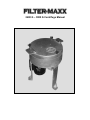
1
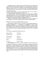
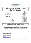
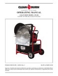
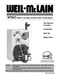
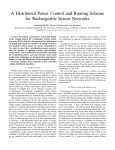
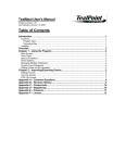
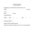
2400 G – 3000 G Centrifuge Manual Thank you for purchasing a US Filtermaxx centrifuge. Handling of fuels and rotating machinery is hazardous. Follow all applicable ordinances regarding handling and storage of fuels, equipment grounding and disposal of centrifuge waste. Filtermaxx LLC is not liable for unlawful use or disposal of waste products. Please read and understand these instructions before use. Warranty: Filtermaxx LLC will repair or replace any part deemed to be defective by Filtermaxx LLC for one year from the date of purchase. Defective parts must be returned to Filtermaxx LLC for inspection. Judgement by Filtermaxx LLC is final. Warranty does not cover shipping charges to or from the Filtermaxx facility. Filtermaxx LLC does not guarantee this product is suitable for any purpose what so ever and is not responsible for any loss or damage from use of this product. Filtermaxx LLC is liable for replacement of defective parts only. Engineering inquires: [email protected] US Filtermaxx LLC PO Box 600711 Jacksonville Fl 32260 USFiltermaxx.com Refuelz.com This Manual Contains Copyrighted Material. Used With Permission. 3 Centrifuge Parts: Left Side Rear Bowl Spindle Assembly 4 Assembly: 1. With the Centrifuge upside down, attach the motor using the bolt in the motor mount hole. Run the bolt up but do not tighten 2. Attach the belt over the small pulley. It should have shipped with the belt over the large pulley on the motor. 3. Take up the slack in the belt using the belt tightening screw seen on the previous page. 5 4. Attach the legs, as seen in the photo, using the bolts found in the bottom of the centrifuge. Be sure that the top rounded edges point towards the inside of the centrifuge. Tighten the bolts using a ¾-inch socket wrench. 5. Using two people, turn the centrifuge over on its feet. Open the lid and remove any packing. Loosen the spindle release and lightly press the spindle to be sure that it is seated. Tighten the spindle release. 6. Tighten the belt so that it is snug but not overly tight. Rotate the bowl by hand to be sure that it turns freely. Tighten the motor mount bolt. 7. Replace and secure the lid. The centrifuge is now ready for use. Safety: There are obvious and not so obvious safety hazards involving oils, centrifuges, static electricity and piping. Stresses in Rotating Wheels: As a wheel spins, centrifugal force attempts to pull it apart. The force is similar to that found in a thick walled cylinder under internal pressure. The stress is the greatest at the inner diameter (center hole) of the wheel and it is at this point where cracks occur. Typically, when run too fast, wheels explode with catastrophic results. Because the forces causing the stress are directly related to the rotational speed, there will always be a speed at which a wheel explodes, regardless of the thickness of the material used. There is a maximum safe speed at which a wheel may be run. The centrifuge has a thick outer casting to contain any flying parts in case of a rupture. While no rupture is expected, do not alter the centrifuge to increase the speed. Never operate the centrifuge without the cover securely attached. Never open a running centrifuge. Flying material from a ruptured bowl may dismember or kill persons nearby. Flammable Vapors: Not all mixtures of fuel and air will support combustion. The limits of which lean and rich mixtures that do support combustion are called the limits of inflammability. The limits of inflammability for oil vapors are from 1.4% to 7.6%. Heated oils may be above the flash point and may reach an explosive mixture, especially in a centrifuge where it is whipped into the air inside the machine. The machine must be vented to the outside or back to the tank so that the vapors may be collected. Static Electricity: A static charge is formed whenever two surfaces are in relative motion. When A liquid flows past the walls of a pipeline or when droplets or particles move 6 through the air, one charge is formed on one surface and an equal but opposite charge is formed on the other surface, for example the liquid flowing past it. Most static charges flow to the earth as soon as they are formed. But if a charge is formed on a conductor or non-conductor which is not grounded, it may remain for some time. If level of the charge or “voltage” is high enough, the static electricity will discharge by means of a spark which can ignite flammable vapors such as oil whipped into the air inside a centrifuge. Examples of nonconductors are plastic and non-conducting liquids such as hydrocarbons. Most liquids containing oxygen atoms in the molecules are good conductors. The centrifuge and all tanks must be connected by ground wires or conducting hoses. Metal tanks are preferred. Static electricity may also be formed on clothing or shoes. Walking across nonconductive flooring or removing coats while wearing non-conductive shoes may build up a charge on a person. Persons working around the centrifuge should always dissipate any charge by touching one of the grounds. Rotating Machinery: Rotating machinery may cut or dismember persons in contact with it. Always stay clear of rotating belts and pulleys. An on/off switch is intentionally NOT included on this machine for two reasons. 1. Switches can cause sparks and 2. If the operator is required to plug in a 6-foot long cord, the operator will be 6 feet away from any rotating parts of the machine. Do not attach a switch to the machine body. Disposal of Centrifuge Sludge: There may be environmental regulations regarding disposal of centrifuge waste in your area. These rules should be followed and supercede any suggestions in this manual. Oily residue, sludge and oily rags are not suitable for disposal in the trash. They should be incinerated on site. Sludge burning furnaces are available for centrifuge drainings, contact Filter-Maxx for more information. Rags may be disposed of by placing them in a small cardboard box and burning the box in a wood stove or furnace. Small amounts of sludge may also be burned in a wood stove or furnace by soaking it up with rags or pouring the sludge over wood in a cool stove. Never attempt to add oil, rags or sludge to a hot stove or furnace. Centrifuge Mounting 7 MOUNTING: see diagram on previous page The centrifuge must NOT be hard mounted. This will tune the centrifuge to a natural frequency causing extreme vibration. It is best mounted on rubber pads with the bolts run down finger tight (lightly tightened) and capped with lock nuts Principle of Operation, manual centrifuge: Centrifuge spinning: Dirty oil enters through the oil-input valve and travels down the tube to the bottom of the spinning bowl where it travels to the vertical sidewall. As the bowl fills with oil, it builds up on the wall of the bowl until it reaches the large hole at the top of the bowl. As it is spinning, dirt travels to the wall of the bowl, water forms an intermediate layer and clean oil spills over the top edge. The clean oil drains down the inside of the centrifuge and collects in the bottom until it reaches the height of the clean oil drain. The clean oil then drains through the clean oil drain. 8 Centrifuge stopped: Upon stopping the centrifuge, the sludge that remains in the bowl slumps down off the wall and drains through the holes in the bowl and exits the centrifuge body through the sludge drain. The centrifuge is restarted and the cycle is then repeated. 2400X This model does not use output valves and may be set up for automatic operation. Clean oil flows through the outer port. Stopping the centrifuge drains the bowl sludge through the center port. An automatic timer is available so that this centrifuge may run unattended Cycle Time: The cycle time is determined by experience with the oil being cleaned. A Starting point may be 1 hour on and 5 minutes off. Adjusting the on time as needed. Flow Rate: The viscosity of the oil and amount of dirt in the oil determine the flow rate. Oils to be cleaned should have a viscosity less than 100 sus. Heating may reduce viscosity. Cleaning the bowl: After several cycles, hard matter or goop resembling grease will build up on the inside walls of the bowl. This should be removed with a rag or wood scraper. Hard deposits may be removed with a rag moistened with gasoline. Cleaning the sump: Periodically, the sump (inside bottom) of the centrifuge should be cleaned. To clean the sump, the machine must be turned off. Loosen the belt adjusting screw and slightly loosen the motor-mount bold as required to remove the belt from the small pulley. Loosen the spindle lock and pull the spindle and bowl straight up and out of the centrifuge. If the spindle is tight, A light blow on the bottom using a hammer and block of wood will loosen it. DO NOT strike the pulley. Clean the sump with a rag. Lubricate the O-ring and spindle bore with oil. Reinstall the bowl and spindle assembly. A light tap (protecting the shaft with a block of wood) at the top of the spindle may be required to start the O-ring in the spindle bore. Tighten the spindle and reinstall the belt. Tighten the belt so that it is snug but not overly tight. Removing the bowl from the spindle: To remove the bowl form the spindle: Mark the collet and bowl so that they may be re-assembled in the same location. Remove the three collet screws and screw them into the bowl release holes. Alternately tighten them to release the collet. Reverse the procedure to reattach the bowl. 9 Natural Frequency: Vibration occurs at the rotational speed and at harmonics or multiples of that speed. For example an 1800 rpm set generates a fundamental frequency of 1800 / 60 seconds = 30 Hz. Harmonics also occur at 60, 90, 120 Hz and so on. Each system will have a natural frequency at which it will ring or amplify the vibration input. A bell rings at a specific tone or frequency. This particular tone is the bell’s natural frequency. When starting and stopping a centrifuge, the speed increases and decreases. During this period, the centrifuge will pass through speeds that relate to its natural frequency and harmonics. As the centrifuge passes through these speeds, vibration will occur. When starting the centrifuge, it will quickly pass through these speeds however, when stopping the centrifuge, it will pass through these speeds more slowly causing a more pronounced vibration. Tanks and Pumping: If there is water present in the oil, gear pumps tend to cause emulsions that may be difficult to break. Vacuum systems are preferred for collection of contaminated oil. Compressed air or inert gas is preferred for transferring oil from the tank. Scrap propane tanks of 120 to 500 gallon capacity are often available at the tank yards of gas suppliers. Applying 20 psi. is usually sufficient to transfer oil from these tanks. All tanks should be vented and grounded. Typical Application: Stop centrifuge to cycle system and flush out sludge from centrifuge bowl. Pressure fed systems may be built with a discarded propane tank using low air pressure, approximately 20 –25 psi, throttling the oil flow as required. Strainers are recommended on the input oil line. Heating the oil and settling may reduce water content of feed oil. 10 OIL FILTRATION AND CLARIFICATION: Gasoline, waste oil, lubricating and fuel oil are filtered to remove dirt, water, metal particles and other foreign matter. By removing these foreign substances, acid and sludge, which result from oil being mixed with this foreign matter, are also reduced. Darkening of oil is mainly due to the introduction of fine carbon, which stays in “colloidal suspension.” Centrifugal clarification removes all impurities except colloidal carbon. TYPES OF CLARIFICATION: Oil cleaning is typically achieved by two methods, precipitation and or filtration. Precipitation includes: Gravity Settling, ForcedCentrifugal and Chemical precipitation. Filtration includes Strainers, Pressure filtration and Coagulation. Usually combinations of several of the above methods are used. Strainers are used for preliminary cleaning and better systems employ parallel strainers so that one may be cleaned while the other is in use. Settling by gravity is a slow process and will not remove fine carbon particles or sludge. The only advantage to settling is its cheapness. Typically the oil is pumped into a large tank and left undisturbed for weeks. Even a slight addition of oil to the tank destroys the necessary quiescence. When this system is employed, it is best to have 2 tanks and alternate the discharge from one to the other as the companion tank is resting. Impurities will not readily settle out of fuels or oils with viscosity of 150 SSU or higher at the storage temperature. Such oil is heated by a hot water coil to 180 or 200 o F, provided this is safely below the flash point. When oils contain more than about .1 percent sediment, it is advisable to purify them by a centrifuge. Two centrifuges in series may be used, one as a purifier to remove water and the second as a clarifier. When cleaning heavy oils by centrifuge, the oil is heated to temperatures above 150 o F. A hot water or heating coil is located around the suction pipe in the storage tank. The hot water pipe should have no joints within the tank. A hot water jacket may also heat the fuel line. Since the fuel may be heated nearly to the gassing point, centrifuges for heated fuel oil should be capable of being closed vapor tight. CENTRIFUGAL PRECIPITATION: When a mixture of oil, dirt and water stands undisturbed, gravity tends to separate the liquid into an upper layer of oil, an intermediate layer of water and a lower layer of dirt or solid material. When the mixture is placed in a rapidly revolving bowl, centrifugal force accelerates the separation. Solids collect upon the bowl, water forms an intermediate layer and clean oil, being the lightest constituent, moves to the center of the bowl. The discharge holes of the bowl may be arranged so that water can be drawn off and discharged. The solids are cleaned from the walls as required. 11 The speed of rotation, viscosity of the oil and the speed of the oil flow through the centrifuge affect the quality of separation. Practical experience dictates the speed of oil flow through the centrifuge for proper cleaning. More material is removed by lower flow rates. If the feed is too rapid, only partial clarification will result. Heating the oil to reduce the viscosity is one of the most effective methods of improving purification. For best results, viscosity of the oil should be less than 100 sus. Tables of viscosity vs. temperature are included for various oils. A centrifuge may be operated as a purifier or a clarifier. If the oil contains water, then a purifier is used. The purifier has two sets of discharge holes. Water is discharged from one set and oil is discharged from another. If the oil contains only solid matter, then the centrifuge is set up as a clarifier by covering the water discharge holes leaving with only the oil discharge holes open. Typically, oils are cleaned at 2000 to 2500 G’s with 1 G being equal to the force of gravity. The G force is dictated by both the bowl diameter and RPM. PROPERTIES OF FUEL OILS AND GENERAL SPECIFICATIONS: Diesel engines are able to burn a wide variety of fuels including mineral oils, animal and vegetable oils. The properties or characteristics of the fuel have considerable influence on the performance and reliability of a diesel engine. While laboratory tests may give some indication of the fuel’s performance, actual fuel performance is sensitive to both molecular arrangement and size. Engine tests should be made to evaluate the suitability of any fuel for a particular service. The principle fuel properties affecting service are: Ignition quality Cloud point Carbon residue Pour point Sulfur content Viscosity Ash content Flash point Water Heating Value Sediment Specific Gravity Ignition Quality: Fuel oils do not ignite immediately upon being injected into the combustion chamber. The interval of time between the beginning of injection and ignition is called ignition lag and varies widely for different fuels when injected into the same combustion chamber. The shorter the ignition delay, the better ignition quality of the fuel. The longer the delay, the more pronounced is the “Diesel Knock.” This is due to the large quantity of fuel that is injected before ignition. When ignition occurs, the flame spreads rapidly through the fuel already in the combustion chamber causing a rapid rise in pressure creating an audible knock. 12 Cetane (C16H34) is a hydrocarbon with a very high and constant ignition quality. If a diesel fuel has the ignition quality of a mixture containing 40% cetane and alpha-methylnapthalene (C11H10) with a low ignition quality, then the cetane number of the fuel would be 40. The cetane number of a fuel is determined by testing it in a standard test engine and varying the compression ratio until the ignition lag is 13 degrees with all other operating conditions (speed, temperature, timing) being constant. The cetane number is the percentage of cetane in a blend of alpha-methylnapthalene that would have the same ignition qualities. High-speed engines require a higher cetane number. Larger, slower diesels with large bores and strokes have more time for ignition and can use fuels with lower cetane numbers. Ignition accelerators are substances that can be added to reduce the ignition delay period. The most effective, among others are amyl nitrate, ethyl nitrate, and ethyl nitrite. The addition of 1% of ethyl or amyl nitrate raises the cetane value of the fuel. A 5% addition may reduce the ignition temperature by 110 o F and increase the maximum cylinder pressure by 120 psi. Viscosity is the opposite of fluidity. It is a measure of a fluid’s resistance to flow or shear. Higher viscosity oils do not flow easily, where low viscosity oil flow readily. This is seen in cold weather as gasoline with a low viscosity flows readily while 40-wt motor oil, with a higher viscosity, is quite thick in comparison. As the temperature of oil is increased, its viscosity is reduced and it flows more readily. A general rule is that an increase of 35 o F. will reduce the viscosity by one half. Viscosity also affects injection characteristics. High viscosity fuels tend to give a coarse, penetrating spray rather than a finely atomized one. Increasing viscosity gives increasing exhaust smoke. Higher viscosity fuels may be used if they are preheated. Low viscosity was believed to have an adverse affect on pump and injector wear, however compared to wear caused by dirt it is minute. Low viscosity fuels may result in increased pump and injector leakage. At a constant pump setting, this leakage reduces the volume of fuel delivered. Specific Gravity: The specific gravity of a fuel has a bearing on the injection properties affecting both the depth of penetration and spray cone angle. A lighter fuel will have a smaller depth of penetration and a larger cone angle. The higher the specific gravity, the greater the carbon content and heating value by volume. However, lighter fuels have a greater percentage of hydrogen and a higher heating value per pound. Pour and Cloud Point: The pour point of a fuel is the lowest temperature at which the oil will flow of its own accord. This determines if a fuel may be pumped at low temperatures. The cloud point is the temperature at which it becomes cloudy due to the formation of wax crystals. This is associated with the clogging of fuel filters and lines. 13 Flash point: As the temperature of fuel oil increases, vapor is given off and collects at the surface. When the temperature rises to a point where the vapors ignite when exposed to an open flame, it has reached its flash point. The flash point is the highest temperature at which the oil can be stored without being explosively dangerous. Flash point has no correlation to the ignition quality of the fuel or engine performance but is of importance in connection with safety and legal requirements. Gasoline has a low flash point but is a poor diesel fuel. The typical flash points of common oils are listed below: Diesel 175 to 220o F Fuel oil 170 to 280o F Lubricating oils 400 + o F Fire point. The temperature at which an oil gives off enough vapor to support sustained combustion is called the fire point. The fire point is usually about 50 degrees higher than the flash point. Carbon Residue: After all the volatile matter in a sample has been evaporated off by heating in a closed container, carbon residue remains. This is a measure of the heavy components that will remain in the engine and form coke. Sulfur: Sulfur may be present in many forms including hydrogen sulfide, which is corrosive. Burning high sulfur fuels forms sulfur dioxide and trioxide, which form acids in the presence of water. High sulfur fuels require more frequent engine oil changes and or additives to reduce the corrosive effects. Sulfur has a lubricating effect on injector pumps. The sulfur content of fuels for high speed engines may be as high as 1%. Low speed engine may tolerate as much as 3%. Air quality standards have dramatically reduced the amount of sulfur in commercial fuels thereby reducing the lubricity of the fuel. Reduced lubricity was associated with early injection pump failures. Recently, the lubricity issues have been addressed. High sulfur content has also been associated with higher particulate matter in the exhaust. Note that current US sulfur standards allow .2% by weight and will drop to 7 parts per million between 2006 and 2011 Corrosion: Is usually measured by immersing a polished copper strip in a fuel for 3 hours at 212o F. This is an indicator of the corrosion expected in copper fuel lines and brass fuel strainers. Ash Content, Water and Sediment: Ash content is found by burning a given quantity at a very high temperature. The incombustible remains are usually impurities such as rust and sand that are extremely abrasive. Water and sediment are measured together. They are separated from the fuel by a centrifuge. These also cause pump and injector wear. 14 Safety: Because of the lower volatility, diesel fuels are generally considered to be much safer than gasoline. However, light diesel fuels carry an explosive mixture above the fuel in a closed tank. Except at very low temperatures, the fuel air mixture is too rich to be explosive in a gasoline tank. Heating Value: Is the actual number of Btu in a sample of fuel. Heating value may be based on weight or volume. Light fuels have a higher heating value by pound, however heavy fuels have a higher heating value by volume. When comparing engine performance on various fuels it is important to evaluate them by heating value of the fuel. Fuel Specific gravity Weight per gallon pounds Btu/pound heating value higher lower Btu /gallon lower Gasoline .702 5.86 20,460 19,020 111,457 Kerosene .825 6.88 19,750 18,510 127,349 Light Diesel .876 7.30 19,240 18,250 133,225 Medium Diesel .920 7.67 19,110 18,000 138,060 Diesel Fuel Grades: No. 1-D Volatile fuel oils from kerosene to intermediate distillates. Used in small high-speed engines with wide variations in load or speed. Also used during very low temperatures. No. 2-D Fuel oils with lower volatility. Used in high-speed engines under high loads and uniform speeds. Mobile service. No. 4-D Viscous fuel and blends used in low and medium speed diesels under uniform load and speed. 15 ANIMAL AND VEGETABLE OILS: PROPERTIES OF SATURATED AND UNSATURATED FATS AND OILS: Chemically, fats and oils are made of carbon and hydrogen. If all of the carbon atoms have two hydrogen atoms attached and no double bonds, then it is said to be saturated. This makes the chains of fatty acids straighter and more pliable so that they fit more closely together and harden at low temperatures. However if there are double bonds present and some carbon atoms do not have two hydrogen atoms attached, it is said to be unsaturated and remains liquid at lower temperatures. Properties of Oils and Esters Oil Type Melting Range Deg. F Iodine Number Cetane Number Raw Oil Methyl Ester Ethyl Ester Corn 23 14 10 115 -124 53 Cotton Seed 32 23 18 100-115 55 Coconut 75 16 21 8-10 70 Olive 10 21 18 77-94 60 Palm 100 57 50 44-58 65 Rapeseed 41 32 28 97-115 55 Soybean 10 14 10 125-140 53 Sunflower 0 10 7 125-135 52 Lard 97 57 50 60-70 65 When fatty acids are broken from the glycerin they retain their double bonds, therefore the biodiesel retains the properties of the fat or oil it was made from. If the biodiesel is made from lard, it will become cloudy at a higher temperature because the lard is solid at a higher temperature. The more double bonds in the original fat or oil, the lower the cloud point of the finished product. Many vegetable oils and some animal oils are drying or semi drying and form the base for paints. The drying properties of these oils cause them to form gums or hard films. Drying results from the double bonds in the unsaturated oil molecules being broken by oxygen and forming peroxides. Cross-linking between molecules occurs at this site and the oil permanently polymerizes into a plastic like solid. At high temperatures found in diesel engines, the process is accelerated and the engine can become gummed up. The drying properties of oils are described by the Iodine Number. Iodine is added to an unsaturated oil to test an oil for double bonds, or degree of unsaturation. The iodine will attach itself over a carbon atom with a double bond, making a single bond. Therefore, iodine numbers describe the amount of iodine required to saturate or break all of the double bonds in the oil. The amount of iodine in grams absorbed per 100 ml of oil is the iodine number of the oil. The higher the iodine number, the greater the tendency of the oil to form gums and hard films. 16 Petroleum Oils 17 Vegetable Oils #1 18 Vegetable Oils #2 19 Filter Maxx Automatic Centrifuge Controller The Filter Maxx Centrifuge Controller is a repeat cycle timer. The controller will start when power is applied. The controller will continue to cycle until power is removed. There is no start circuit and the timer resets upon power interruption. T1 is the cycle run time in hours. T2 is the off cycle in minutes. The pilot light indicates cycle progress by blinking at an ever increasing rate as the cycle progresses. The blinking patter occurs every 3.5 seconds and will consist of one blink during the first 10% of the cycle, two blinks during the second 10%, 3 during the third, etc. The range of cycle time “minuteshours-10 hours: may be adjusted by inserting a screwdriver through the holes in the side of the case and turning the range selector. T1- cycle run time in hours T2 – cycle off time in minutes The Filter Maxx 2000X Centrifuge automatically drains the liquid sludge from the bowl when stopped. The centrifuge controller and input solenoid valve allow unattended operation of the centrifuge. Typical cycle time for the Filter Maxx 2000X centrifuge is 1 hour on 4 to 5 minutes off. However, all oils are different and the cycle may be adjusted as required to flush the centrifuge. The solenoid valve is normally closed and opens when 120 volts is applied to the wire leads. Solenoid leads are spliced into the motor terminal box using the supplied wire nuts. One wire to the black lead and one wire to the white lead. The controller requires a 120 volt 20 amp electrical circuit. Minimum wire size for connection is 12 awg. Pumping the oil to the centrifuge usually forms an emulsion that is difficult to break. The preferred method is to use a feed tank or pressure vessel, such as a discarded propane tank, 100 to 500 gallons capacity, applying approximately 20 psi air pressure to the tank forcing the oil through a line to the solenoid valve. The sludge tank must be the same capacity as the feed tank to prevent a spill in case of accidental centrifuge over flow. 20 Troubleshooting: 1. Rattles or Vibration: Loose spindle Tighten spindle lock Loose Pulleys Tighten pulley set screwsBe careful not to strip the aluminum threads by over tightening. Motor mount loose Tighten motor mount bolt Legs rigidly bolted to an uneven surface. Use rubber pads under the legs. Tighten only 1 leg bolt leaving the other two only finger tight. Over tightening can actually “tune” the centrifuge to a natural frequency causing severe vibration 2. Centrifuge Stutters upon start up: Belt is loose Tighten Belt 3. Centrifuge runs for a while then blows breaker upon restart: Breaker too small. 20 amps required for cycling operation. 15 amps may start and run the centrifuge, but is too small for restart. 4. Centrifuge will not start: Bowl jammed Remove jam. Reposition bowl so that it spins freely Belt too stiff to bend over small pulley. Use a 3L belt for aluminum pulleys. 4L for steel pulleys Circuit breaker blown Determine cause of blown breaker, then reset. Motor and capacitor heat up upon starting. No more than 4 starts per hour allow capacitor to cool between starts. Capacitor bad Capacitor oil leaks out upon over heating. Replace capacitor. 21 Motor Wiring: Single phase: 240-volt operation has much better starting characteristics and is preferred. Three Phase: Has superior starting characteristics 22 Warranty Registration: Return to: Filter-Maxx, PO Box 600711, Jacksonville, FL 32260 Warranty: Filter Max LLC will repair or replace any part deemed to be defective by Filter Maxx LLC for one year from the date of purchase. Defective parts must be returned to Filter Maxx LLC for inspection. Judgment by Filter Maxx LLC is final. Warranty does not cover shipping charges to or from the Filter Maxx facility. Filter Maxx LLC does not guarantee this product is suitable for any purpose what so ever and is not responsible for any loss or damage from use of this product. Filter Maxx LLC is liable for replacement of defective parts only. Model__________________________ Serial Number __________________ Date of purchase ___________________ Owner___________________________________________________________ Street___________________________________________________________ City, State, Zip____________________________________________________ Email___________________________________________________________ Rate Our Service: Was your order promptly shipped?_________ Was the order correct? __________ Was it properly packed and arrive undamaged? __________________________ Is the manual helpful?_______________________________________________ Does the manual properly answer your questions?________________________ What can we do to improve? You may answer on the back of this page. 23