1
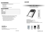
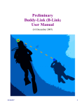
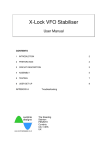
A and T Labs K10 Mapper8 User’s Manual A and T Labs Inc. P.O. Box 4884 Wheaton, IL 60187 Tel: 630-668-7870 Fax: 630-668-7870 Web: www.a-and-t-labs.com Technical Support: [email protected] 2001 A and T Labs Inc. UMK10a A and T Labs K10 Mapper8 User’s Manual Table of Contents 1. Introduction ............................................................................................................................................... 1 2. Using the Mapper8 ................................................................................................................................ 1 3. Summary and Tips .................................................................................................................................... 2 2001 A and T Labs Inc. UMK10a A and T Labs K10 Mapper8 User’s Manual 1 1. Introduction Congratulations on purchasing the Mapper8 cable tester! The Mapper8 provides complete connectivity testing of 8-wire modular cables as well as other cables. The Mapper8 can very quickly check for wiring problems such as opens, shorts, reversed pairs, etc. Connectivity is compared against a predefined or a user-defined connectivity map. The Mapper8 displays both a quick pass/fail indication as well as details on how the cable is wired or mis-wired. 2. Using the Mapper8 The Mapper8 consists of two separate units; a master unit and a remote unit. A remote unit is attached to one end of the cable, turned on, and set to Remote mode. The remote unit responds to requests from the master unit with a coded message back to the master. Each message contains the remote’s ID, allowing the remote to be uniquely identified. Next the master unit is attached to the other end of the cable, and the cable is then tested by depressing the master’s test button. The test results as well as the remote’s ID are displayed on the master unit’s LEDs. CAUTION: Make sure that the cables under test are disconnected from any possible power source! Connecting the Mapper 8 units to a cable with voltages present can result in damage to the units and/or personal injury! Groups of installed cables can be rapidly tested and identified by using multiple remote units each with a different remote ID. A remote is attached to one end of each cable, then the master unit is connected in succession to the other end of each cable. Each cable is tested and the attached remote identified. Up to eight different remote units can be used in this manner. Figure 1 illustrates an example test setup using multiple remotes to test three cables strung between four rooms. When the master’s TEST button is depressed, the master unit begins sending a request pulse down each of the wires it is attached to, then looks for response messages from a remote. By noting which message is received on which wire, the master unit can build a map of connectivity between itself and the remote unit at the far end of the cable. Once the map is complete, the master unit compares the connectivity map against a predefined or a user-defined connectivity map. If the maps are the same, the master unit lights the PASS LED, otherwise it lights the FAIL LED. Figure 2 illustrates the master unit’s display during this testing phase. Finally, the master unit proceeds to display the connectivity mapping on its set of LEDs. Figure 3 illustrates the master unit’s display during this readout phase. The group of eight red LEDs on the master unit displays several different types of information. When the MAP LED is lit, these eight LEDs indicates which of reference connectivity map will be used for the test. When the REMOTE LED is lit, these same eight LEDs indicate the ID received from the remote unit. When the NEAR and then FAR LEDs are lit, these eight LEDs display the measured cable connectivity between the remote unit (the near end) and the remote unit (the far end), respectively. The PROG button can be used to change the selected reference connectivity map to a different map. Either a predefined map or a user-defined map may be selected. See Figure 2 for details on changing the map. Figure 4 illustrates the three predefined connectivity maps supported by the master unit. The PROG button is also used to change the user-defined maps. The master unit can store four userdefined maps: map1, map2, map3, and map4. To set a user map up, first test a known-good cable of the desired connectivity, then use the PROG button, as detailed in Figure 3, to store the map into the master unit. 2001 A and T Labs Inc. UMK10a 2 A and T Labs K10 Mapper8 User’s Manual Remote units can be operated in two modes. The PROG button is used to select which mode the remote unit will operate in. When the PROG button is depressed while the unit is turned on, the current mode of the unit will toggle to the other mode. The first mode is the normal remote mode where the remote unit is used in conjunction with a master unit for connectivity testing. In this mode, the remote unit transmits coded messages down each of the wires it is attached to when requested by the master unit. The messages contain the remote’s ID allowing the remote to be uniquely identified by the master unit. Figure 5 illustrates the remote unit in remote mode. When in remote mode, the REMOTE ID LED flashes and one of the eight red LEDs flashes corresponding to the selected remote ID. The PROG button is used to change the remote unit’s ID. See Figure 5 for details on changing the ID. The second mode is a tone generation mode. In this mode, the remote sends an audio tone down the wires instead of messages for the master unit. By using a standard signal or tone tracing amplifier tool, this tone can be heard anywhere near the cable without having to electrically connect to the cable. This is useful for identifying a desired cable, say within a bundle of cables, without having to crimp connectors on cables first. Figure 6 illustrates the remote unit in tone mode. The warbling tone can be transmitted on an individual wire pair of the cable or simultaneously on all four pairs. When in tone mode, the TONE LED flashes and a pair of red LEDs corresponding to the selected pair flash as well. See Figure 6 for details on changing which pair receives the tone. 3. Summary and Tips Other cable types such as coax and others can be tested by building short cable adapters to the 8-wire modular jack. Cables with fewer wires can be accommodated by building an adapter connecting to only a subset of the modular jack. Using the adapters, test a likely-good cable and study the connectivity results. If the connectivity is correct, then store the map into one of the programmable reference maps (map1, map2, map3 or map4). The Mapper8 is now ready to rapidly test more of these new cables. If you are testing a cable run that is made up of several individual cables chained or patched together, be sure to test the intermediary cables as well as the complete cable run. Two wrong cables in the chain could make the whole look correct! Keep in mind that the Mapper8 does not test all the cable parameters that might be important to some applications. For example, networking cables need to have specific impedance, cross-talk, length, etc. characteristics. By using the appropriate raw cable and carefully following recommended cabling practices these requirements can be easily met. That said, the Mapper8 is a versatile and inexpensive addition to your toolbox! 2001 A and T Labs Inc. UMK10a A and T Labs K10 Mapper8 User’s Manual 3 Remote Unit with ID=1 Room A Master Unit moved between each cable. Testing and identifying each cable. Room B Remote Unit with ID=2 Room D Remote Unit with ID=3 Room C Figure 1 - An example test setup using multiple remote units to test multiple cables 2001 A and T Labs Inc. UMK10a 4 A and T Labs K10 Mapper8 User’s Manual Press and hold the TEST button to start testing At this point only, the selected map can be changed. Press and hold the PROG button until the MAP LED blinks once. Release the PROG button. Each push of the PROG button will select the next successive map. Release the TEST button when the desired map is selected. MAP 1 MAP 2 MAP 3 MAP 4 REVERSE Map CROSS The currently selected map is displayed indicating which connectivity map will be assumed. In this example, the CROSS map is selected. STRAIGHT A display test is performed by rapidly lighting each LED in sequence Prog 8 7 6 5 4 3 2 1 Remote Near Far The measured connectivity is compared to the selected map and either the PASS or FAIL LED is lit and remains lit. In this example, the comparison passed. MAP 1 MAP 2 MAP 3 MAP 4 REVERSE CROSS Map STRAIGHT Each successive wire LED (1 through 8) is lit, indicating scans for messages from the remote are in progress. Prog 8 7 6 5 4 3 2 1 Remote Near Far Pass Fail If the TEST button continues to be held down, the Master Unit will proceed to the Readout Phase. Figure 2 - Master Unit Test Phase. The progression of the master unit’s test phase ends with an easy to read pass or fail indication. 2001 A and T Labs Inc. UMK10a A and T Labs K10 Mapper8 User’s Manual 5 The readout phase repeats until the TEST button is released. MAP 1 MAP 2 MAP 3 MAP 4 CROSS REVERSE MAP 1 MAP 2 MAP 3 MAP 4 REVERSE CROSS MAP 1 MAP 2 MAP 4 REVERSE CROSS STRAIGHT MAP 3 MAP 1 MAP 2 MAP 3 Map MAP 4 In this example, the first of the 8 mapping pairs is shown: near wire 1 is connected to far wire 8. Prog 8 7 6 5 4 3 2 1 Remote Near Far REVERSE A total of 8 mapping pairs is shown in order of near wire 1 through near wire 8. Prog 8 7 6 5 4 3 2 1 Remote Near Far Map The measured connectivity map is displayed by showing pairs of near-to-far wire number mappings. Wire numbers relative to the Master Unit are near and numbers relative to the Remote are far. STRAIGHT Map The ID of the Remote Unit is displayed. In this example, the messages were received from remote with ID 5. Prog 8 7 6 5 4 3 2 1 Remote Near Far CROSS At this point only, the newly measured connectivity map can be stored into the Master Unit, if the currently selected map is one of MAPS 1-4. Press and hold the PROG button until the MAP LED begins to blink. The measured map is now stored in the selected map. Map STRAIGHT The currently selected map is again displayed indicating which connectivity map will be assumed. In this example, the CROSS map is selected. STRAIGHT If the TEST button continues to be held down, the readout phase is entered from the test phase Prog 8 7 6 5 4 3 2 1 Remote Near Far Figure 3 - Master Unit Readout Phase. The master unit’s readout phase shows the complete detail of the connectivity between the master and the remote. 2001 A and T Labs Inc. UMK10a 6 A and T Labs K10 Mapper8 User’s Manual STRAIGHT = 8 wires straight through 1 2 3 4 5 6 7 8 1 2 3 4 5 6 7 8 CROSS = crossover cable for 10baseT, 100baseTX, 100baseT4 1 2 3 4 5 6 7 8 1 2 3 4 5 6 7 8 REVERSE = 8 wires reversed 1 2 3 4 5 6 7 8 1 2 3 4 5 6 7 8 Figure 4 - Predefined Connectivity Maps. 2001 A and T Labs Inc. UMK10a A and T Labs K10 Mapper8 The unit is in remote mode. The blinking numbered LED indicats the remote’s ID. In this example, the ID is 5. To change the remote’s ID: Press and hold the PROG button for ~15 seconds until the numbered LED stops its blinking. Release the PROG button. Each push of the PROG button will select the next successive ID. Turn the remote unit OFF then back ON when the desired map is selected. User’s Manual Remote ID 7 Prog 8 7 6 5 4 3 2 1 PAIR 4 PAIR 1 PAIR 2 Tone PAIR 3 T568B Figure 5 - Remote Unit in Remote Mode. In this mode, identifying messages are sent down each wire to be received by a master unit. The unit is in tone mode. The blinking numbered LEDs indicate on which pair the tone is transmitted. In this example, the tone is on Pair 3 (wire 3 and 6). To change the tone pair: Each push of the PROG button will select the next successive pair. Remote ID Prog 8 7 6 5 4 3 2 1 PAIR 4 PAIR 1 PAIR 2 Tone PAIR 3 T568B Figure 6 - Remote Unit in Tone Mode. In this mode, a tone is continuously transmitted down the selected pair of wires 2001 A and T Labs Inc. UMK10a