1
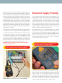
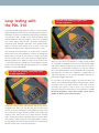
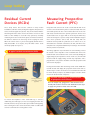
FREE
Step-by-step
guide to easy
PART P
Loop Testing
using the PDL 310
Issue no. 01/07
Loop testing
What IS the Loop and
why must it be tested?
Setting up the PDL 310
You must first understand that the loop to be tested includes the
supply system, so the mains must be switched on to carry out
When a fault occurs in an electrical system, the over-current device
a test.
must open the circuit to cut off current quickly. In domestic circuits
this device will be a miniature circuit breaker (MCB) or a fuse, both
of which operate when the current they carry exceeds the rated
value. The supply voltage drives this fault current, the value of the
current depending on this voltage and the resistance (strictly the
impedance) of the circuit in which it flows. A higher voltage or lower
impedance will result in a greater current and a faster time of
operation of the fuse or of the circuit breaker.
It is of the greatest importance that the circuit concerned is
disconnected as quickly as possible, to prevent dangers due to
Caution
We strongly advise reading and understanding
this guide before the instrument is used.
In particular note the safety issues that follow:■
Although fully protected up to 600V AC this tester
is for use on 230V AC circuits only.
■
Always check the tester on a known correctly wired
live socket outlet before and after use.
■
Before use - check your tester for any
damage to the plug, lead and cabinet.
electric shock or to fire. The supply voltage is fixed by the Supply
Company, so to achieve the greatest possible level of safety we must
ensure that the impedance of the path taken by the fault current is
low enough to ensure rapid operation of the protective device. This
path is called the earth fault loop, or sometimes simply the loop.
This loop may be extensive, going through the installation itself and
all the way back to the Supply Company’s transformer. The PDL 310
measures the impedance of this loop, and thus checks the safety of
Plug the tester into a socket on the circuit to be tested as shown
in Figure 1.
the system.
The lower the loop impedance, the greater the fault current and the
more quickly the circuit is disconnected. So what should the value be?
Loop impedance values
There is no single, simple answer to the question “What is an
acceptable value for fault loop impedance?” The answer is, of
course, the impedance that will allow enough fault current to
operate the fuse or circuit breaker quickly enough to prevent
damage to the installation or to those using it. But this impedance
depends on the exact operating characteristics of the fuse or the
circuit breaker concerned, as well as on the rating of the device.
For example, a rewireable fuse requires lower loop impedance
than does a cartridge fuse, whilst the acceptable value is higher
for a miniature circuit breaker. Again, a 30 A fuse will require a
much lower loop impedance value than will a 5 A fuse.
Exact maximum values for loop impedance are to be found in
tables forming part of the IEE Wiring Regulations (BS 7671). This
publication can be difficult to interpret. A little later a simplified
explanation of the acceptable results will be given.
1
The PDL 310 connected ready for use
Switch the socket on, when the instrument will go through its
pre-test routine. The three LEDs in the orange triangle on the tester
Reversed Supply Polarity
will be a steady green accompanied by a series of bleeps while the
instrument sets itself up into its operating condition. If the LEDs are
It is seldom appreciated that the supply to an installation can be
not all green (indicating faulty wiring or connections), the tester will
misconnected so that the live (phase) and neutral/earth supply
automatically lock out to prevent further tests. Should any of the
conductors are reversed. This state of affairs is extremely rare, but
LEDs in the triangle be lit or flashing as red or orange accompanied
very dangerous indeed, because the live (phase) of the supply
by a warbling tone, this indicates a wiring fault, the nature of which
system will in many cases be connected directly to the earthing
is shown by the list on the front of the instrument and in more detail
system, so that all earthed metal will become live. If this mistake
by the table on the back of this Guide. This extremely valuable test
has been made there will be no obvious sign, with sockets and all
facility is built in to the PDL 310. Such faults may require assistance
equipment operating normally and most loop impedance testers
and advice to correct them.
will not show that a dangerous situation exists.
In the event of a socket not being available, the PDL 310 loop tester
The supply polarity can be verified by applying firm (thumb)
can be powered by connecting it to any suitable supply, possibly at
pressure onto the orange area at the bottom of the front panel of
a consumers unit, using a fused test lead set. Care must be taken to
the tester, which is labelled PRESS AND HOLD. Note that this
ensure that the brown lead is connected to the phase (live). Note
area does not depress as is the case with the ON/OFF, PFC and
this picture shows using the Socket & See ITLS 400 fused test lead
LOOP-PFC TEST buttons above it.
set, the blue neutral probe can be ‘piggy backed’ into the green
orange triangle remain green as shown in Figure 3, polarity is
(earth) unit and then a croc clip attached to the front of the green
correct and the loop test can proceed.
If the three LEDs in the
unit. Your tester is now a two wire testing device and measurement
can be made between phase-neutral or phase-earth.
WARNING: Always make the Neutral or Earth connection
before connecting to Phase.
2
3
The PDL 310 showing correct connections
and displaying the supply voltage.
The PDL 310 PLUS* connected to a consumers
unit using the fused test lead set supplied.
Below these indicators, the display screen will show the supply
voltage. In theory, the nominal supply voltage for the UK is 230
V, but in practice it is more usually around 240 V. If the supply
voltage is outside the permitted limits of 207 V to 253 V, the
tester will be automatically prevented from carrying out further
*Please note: the ITLS 400 test lead set is only included with
tests. In this (unlikely) event, expert help, probably from the
PDL 310 PLUS. It is an optional extra for standard PDL 310.
customers Supply Company, will be an urgent necessity.
Loop testing with
the PDL 310
5
The PDL 310 showing a higher value
of loop impedance.
Leave the PDL 310 plugged into its socket (or connected to the
supply with the fused test lead set). Check that the three LEDs in
the triangle are all green and that the supply voltage is within the
correct limits of 207 V to 253 V. Now press the button below
marked LOOP-PFC TEST. There will be a short series of flashing
zeros on the display whilst the test is underway, followed by a
sharp beep sound. During this period the “wait” symbol will also
appear to the left of the display. Then the value of the loop
impedance will appear on the display for about five seconds.
If the reading is less than 1Ω this is an excellent result, a value we
would expect from most installations fed from an underground
supply, which are known as TN systems (see Figure 4). Possibly
the only situation where this result would not comply with the
Wiring Regulations is if it applies to a high-current circuit (such as
There are cases where loop impedance readings as high as 10 Ω
a cooker) protected by a rewirable fuse. This is unlikely in modern
are acceptable in installations fed from an underground supply
practice, and could be rectified by changing the fuse for a suitable
(TN systems), but these apply only to circuits fed from very low-
miniature circuit breaker (MCB).
rated fuses or circuit breakers (usually 5 A or 6 A). The installer
4
The PDL 310 showing a measured value
of loop impedance
who is not totally familiar in electrical installation theory would be
well advised to treat 2Ω as the maximum acceptable value of
earth-loop impedance for an electrical installation fed from an
underground supply (TN system).
In cases where the electrical supply is by overhead cables (TT
system), it is very likely that high values of loop impedance will be
encountered due to the high resistance of the earth electrode
connecting the system to earth. In these cases, electric shock
protection cannot be provide by fuses or circuit breakers, and the
IEE Wiring Regulations require that residual current devices
(RCDs) are fitted to provide this protection.
Should the reading be above 1Ω but below 2Ω, this may well be
acceptable. First make sure that the plug pins and the socket
contacts are clean by unplugging and re-plugging the plug several
times, and then test again. Another possible reason for the high
reading is if the socket under test is distant from the incoming
mains. The longer the cables feeding the outlet, the greater will be
their resistance and the higher the loop reading will be. However,
it is very unlikely that cables feeding an outlet are so long that they
will have a major effect on the loop impedance.
Loop testing
Residual Current
Devices (RCDs)
Measuring Prospective
Fault Current (PFC)
These safety devices have become common in many modern
Prospective fault current is the electric current that will flow in the
installations, both those fed by underground supplies (TN systems) as
event of a short-circuit from live phase to earth (or neutral). This is the
well as overhead supplies (TT systems). They are intended to limit the
current that operates the fuse or the circuit breaker in the event of an
time during which the electric shock received in the event of an earth
earth fault, and which therefore provides protection. All fuses and
fault to a value unlikely to case death. They operate by constantly
circuit breakers have an upper limit of current beyond which they
monitoring the electric currents in live (phase) and neutral conductors,
cannot be relied upon to operate safely, and the installation designer
the difference between the two being current escaping the earth.
must choose protective devices that will deal safely with the
When this current reaches a preset level (typically 30 mA which is
maximum current possible in a particular case. In order to do so, he
thirty thousandths of an ampere), they will switch off the circuit
will calculate the maximum current that can flow, and will need to
extremely rapidly. (See Figure 6).
verify this in the completed installation by measuring it. The PDL 310
will carry out this measurement.
6
A typical residual current device (RCD)
The voltage applied to any circuit drives the current flowing in it and
the resistance or the impedance of the circuit limits this current. The
maximum fault current value therefore can be found by dividing the
supply voltage by the impedance it meets. In this case, the PDL 310
measures both the supply voltage and the loop impedance and is
programmed to carry out the calculation so that the prospective fault
current can be displayed.
Pressing the PFC button after first having carried out the LOOP-PFC
test will calculate and display the prospective fault current value as
shown in Figure 7. If the current does not exceed 999 A the value will
be shown directly in amperes (A) whilst for higher currents it will be
A. RCD in consumers unit
measured in kA (thousands of amperes).
B. Plug-in RCD for
protection of single
appliance
7
The PDL 310 showing a measured value
of prospective fault current.
This is an example only, (plugged into a 13A standard socket) –
normally PFC would be measured at the distribution board origin
of supply using fused test leads) such as ITLS 400.
C. Socket outlet incorporating RCD
To measure the impedance of the earth fault loop, a current is
deliberately passed through it, in most cases tripping the RCD. The
PDL 310, however, has special circuits to prevent this from happening,
thus removing the need to short out the RCD, which is a skilled task
and not recommended in current guidance notes.
The PDL 310 has a number
of other features in its design
that are useful to the user.
Condition
Number
Wiring
Condition
Supply
Terminal
N
These are:-
LED
Display
E
N
E
2
L-E reverse
N
3
L-N-E miswire
E
repeated use and if a high temperature
4
L-N reverse
L
is reached this could affect the accuracy
5
L-N-E miswire
L
has an automatic cut-out to inhibit its
6
Faulty N / L-E miswire
NC
use if such a temperature is reached, and
7
Faulty N / E miswire
NC
the thermometer symbol appears in the
8
Faulty N
NC
The instrument can warm up with
of the readings obtained. The PDL 310
display to the left of the voltage display.
L
Socket Wiring
Correct
Operating temperature
cut-out
Buzzer
1
L
Continuous
L
E
Warble
L
N
Warble
E
N
Warble
N
E
Warble
L
N
Warble
N
L
Warble
E
L
Warble
If this happens, switch the instrument
9
Faulty N / L-E reverse
NC
L
E
Warble
off – when it has cooled down, it will
10
Faulty E / L-N reverse
L
NC
N
Warble
11
Faulty E
N
NC
L
Warble
12
Faulty E / N miswire
E
NC
L
Warble
13
Faulty E / L-N miswire
L
NC
E
Warble
switched off to prevent unnecessary battery
14
Faulty L / N-E miswire
L
N
NC
Warble
drain. The instrument has a feature that
15
Faulty L / E miswire
N
L
NC
Warble
automatically switches off after about two
16
Faulty L / N-E miswire
E
L
NC
Warble
17
Faulty L / N miswire
L
E
NC
Warble
18
No Mains
NC NC NC
None
automatically reset and test correctly.
Automatic switch off
After use, the instrument should always be
minutes if this is forgotten.
Batteries
The PDL 310 uses 4 x AA batteries, and
ideally good quality alkaline types should
be used. A new set of these batteries
can be expected to complete more than
LED’s will flash to indicate fault condition
NC=No Connection
10,000 tests. (or the shelf life of the batteries).
Socket & See Industrial
www.socketandsee.co.uk
Unit 4, Century Road, High Carr Business Park,
Newcastle, Staffordshire, UK, ST5 7UG
T +44 (0)1782 567096
F +44 (0)1782 567095
NOTE:
This document is intended as a Guide to Loop Testing only and
reference should be made to the PDL310 User Manual for full
operating instructions before any tests are undertaken.