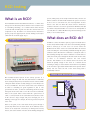
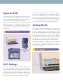
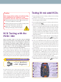
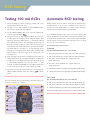
1
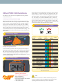
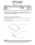
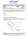
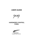
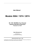
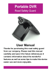
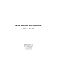
FREE
Step-by-step
guide to easy
PART P
RCD Testing
using the PDRC 380
Issue no. 01/07
RCD testing
What is an RCD?
The initials RCD stand for Residual Current Device – so where does
that get us? The dictionary tells us that the word “residual” refers
to “something remaining”, so a residual current device must be
concerned with something left over after two currents have been
compared. In fact, the RCD is an electrical device intended to
protect people and property from currents flowing incorrectly to
person, which part(s) of the body in which it flows, the time for
which it continues to flow and the health of the person concerned.
As far as we are concerned here, the most important of these
factors is the time for which the shock current is allowed to
continue. If the time concerned is greater than 40 milliseconds (40
ms, which is forty thousandths of a second or one twenty-fifth of
a second) there is a distinct likelihood of permanent damage to the
victim, or even of their death.
earth from the electrical supply. (fig 1).
1
A typical RCD in a consumer unit
What does an RCD do?
An RCD is a device intended to protect people from death due to
RCD Unit
electric shock, which usually occurs due to current flowing through
them to earth (fig 2). In some cases it is used to reduce the
likelihood of fire in the event of an earth fault. When an electrical
circuit is healthy, the current flowing outwards through the phase
conductor (often called the live conductor) is exactly the same as
that returning through the neutral conductor. If current flows to
earth, this current passes through the live but returns via the earth,
so
there
is
an
imbalance
between
live
and
neutral
currents. This imbalance is the residual current. The device will
switch off quickly enough in the event of a residual current
exceeding its rating to ensure that the shock victim is very unlikely
to die. It must be appreciated that the RCD cannot prevent electric
shocks, but can ensure the risk of the shock being fatal is
considerably reduced.
2
Our standard electrical system in this country operates at a
theoretical voltage of 230 volts AC (abbreviated to 230V AC)
above earth potential; in fact, for historical reasons connected with
a European Union decision to unify voltages, it is more likely to be
in excess of 240V AC. The word “earth” in this sense should not
be taken as something we grow vegetables in, but as “the
general mass of earth”, or all of our surroundings, the floors, walls,
metal parts in our homes and so on. In the event of an earth fault,
where a live system makes contact with this “general mass of
earth”, a current, known as the earth fault current, flows to earth.
If this current is large enough and passes through part of a
building, a water pipe for example, the heat it generates may well
cause a fire.
More to the point, if the earth fault current passes through a
person, they will receive an electric shock. As we all know, electric
shocks can be fatal; how serious they are will depend on many
factors, such as the amount of electric current flowing through the
Electric shock due to lack of RCD
Types of RCD
It would be perfectly possible to design an RCD with a rating of 1
mA, a current so low that there can be no danger of death due to
The RCD can exist in a very wide variety of forms (fig 3). In some
cases, it will form part of the plug used to supply an appliance
(such as a hedge trimmer or a lawn mower) or it may be incorporated
in the socket outlet into which the appliance is plugged.
electric shock. Unfortunately, due to the fact that electrical
insulation is never perfect, and another effect called capacitance,
there is always a leakage current to earth of more than this value,
even in a perfectly healthy circuit. Thus, an RCD with a rating as
low as this would trip at once, and so would be impracticable.
In other cases it may be included in the consumer unit, together
with the protective fuses or circuit breakers, to protect the complete
electrical installation or a part of it. Another possibility is that it is
incorporated into a circuit breaker whose purpose is to protect a
specific circuit.
Testing RCDs
It is essential to ensure that the RCD will operate as intended to
prevent danger, so it must be tested. All RCDs are provided with a
3
test button (fig. 4) that should be pressed regularly by the user. This
Different types of RCD
system tests that the RCD will open the circuit, and does not take
any account of how long it takes to operate. This test should be
carried out periodically by the user and is very useful to check the
basic operation of the device, but is quite useless to confirm that
the user will be protected in the event of an electric shock. This test
does NOT take the place of the tests we are about to explain.
The PDRC 380 RCD tester is designed to measure exactly the
fraction of a second taken for the device to operate in the event
of a fault, which is displayed in milliseconds (ms), which are
thousandths of a second.
A. RCD in consumers unit
B. Plug-in RCD for
protection of single
appliance
4
RCD Test button
C. Socket outlet incorporating RCD
RCD Ratings
The rating of an RCD has nothing to do with its ability to handle
the current to the appliance or the circuit protected, but is the
value of residual current at which it will operate. Thus, an RCD in
a typical domestic situation may well be able to switch off the load
current of 40 A but be rated at a residual current of 30 mA (thirty
thousandths of an ampere). RCDs are made with a wide range of
ratings, but by far the most common are 30 mA and 100 mA.
Test Button
Testing 30 mA rated RCDs
Caution
We strongly advise reading and understanding
this guide before the instrument is used.
In particular note the safety issues that follow:■ Although fully protected up to 600V AC this tester
is for use on 230V AC circuits only.
■ Always check the tester on a known correctly wired
live socket outlet before and after use.
■ Before use - check your tester for any
damage to the plug, lead and cabinet.
1. First go through the checks of voltage, polarity, and correct wiring
detailed on the back cover.
2. The tester is set to 30 mA using the TRIP CURRENT button (5),
when the display will show 30 mA.
3. Use the SELECT PHASE button (7) to select the positive half-cycle
for test, indicated by
.
4. The tests are made with the trip current set to 100% (full) rated
tripping current using the SELECT TEST button (6) so that the display
shows x 1 – this will be 30 mA for a 30 mA rated device. This full
tripping current must not flow for more than 2 s (two seconds),
and the test instrument automatically controls this requirement.
The RCD should then trip within 200 ms (one fifth of a second),
RCD Testing with the
PDRC 380
although in the majority of cases tripping will be likely within 30
milliseconds (30 ms).
5. Repeat the test with the negative half-cycle selected using the
SELECT PHASE button (7), when the symbol
will be shown.
Before proceeding, switch on the tester using the ON/OFF
Make a note of the greater of the two trip times for record purposes.
button and ensure that the orange triangle has three green LEDs
6. In the case of a 30mA RCD only, all of these tests are then repeated
before proceeding. If they are not, investigation is required (see
again with the test current set to 150 mA using the SELECT TEST
(A) “Checking correct wiring condition of supply” on back cover).
button (6), when x 5 will be displayed. Results are likely to be a
Next check that the supply voltage displayed is within the limits
little quicker than the previous tests, but again must not exceed
of 207 to 253 V – if it is not (very unlikely), arrange for the
40 ms. Again make a note of the larger of the two trip times for
customer to contact their Electricity Supply Company.
record purposes.
Two of these tests are necessary at each stage, with the test
7. Next select 50% (a half) of the rated tripping current using the
current starting in different half-cycles of the alternating supply.
SELECT TEST button (6) – this will be 15 mA for an RCD rated at
Our standard supply system is alternating current at 50 Hz (Hertz),
30 mA (50mA for a 100mA RCDs). Press the TEST button (9),
or 50 cycles per second. For one hundredth of a second (10ms) the
when this fault current is maintained for not more than 2 s (two
voltage and current are in one direction (the positive half-cycle)
seconds). The RCD should NOT trip. This will be indicated by a
before reversing for the same time in the negative half-cycle (fig 5).
series of bleeps from the tester and a display of >2.00 s.
8. Repeat the test with the negative half-cycle selected using the
5
Positive & negative half-cycle indicators
= 0˚ or (positive)
=180˚ (negative)
The RCD trip time can be affected by the direction of the test
current, so tests must be carried out for both half-cycles. The halfcycle
during which the test current is applied is chosen using the
SELECT PHASE button (7), when symbols in the display will show
the chosen starting half-cycle. Typically there will be a discrepancy
of up to 10 ms between the two readings, and the larger of the
two must be assumed and recorded for test purposes.
SELECT PHASE button (7), when the symbol
2
Three LED’s show
socket wiring status
7
Selects phase
angle the test
will start from
= 0˚ or
=180˚
8
Manual or auto
test sequence
9
Push to start test
4
Polarity Test
will be shown.
1
On/Off button
3
Correct mains
voltage indicated
5
Selects RCD
rating for 30mA
and100mA (I∆n)
6
Selects test to
be applied x 1 Trip x 5 - Fast trip
(30mA RCD only)
x 1/2 - No trip
RCD testing
Testing 100 mA RCDs
Automatic RCD testing
1. First go through the checks of voltage, polarity, and correct
Whilst complete operator control is assured by the manual testing
wiring detailed on the back cover.
described above, it can be time consuming and is subject to
2. The tester is set to 100 mA using the TRIP CURRENT button
operator error. The PDRC 380 has a unique feature that takes
away the need for manual input of testing details.
(5), when the display will show 100 mA.
3. Use the SELECT PHASE button (7) to select the positive halfcycle for test, indicated by
.
If the MANUAL/AUTO
button (8) is pressed the display will
4. The previous tests are then repeated with the trip current set
indicate AUTO, when the tests will be automatically selected. Press
to 100% (full) rated tripping current using the SELECT TEST
the TEST button (9) and note the result of your test. Reset the RCD
button (6) so that the display shows x 1 – this will be 100 mA
if it has tripped. Press the TEST button (9) again, and so on, until
for a 100 mA rated device. This full tripping current must not
the series of tests is completed.
flow for more than 2 s (two seconds), and the test instrument
automatically controls this requirement. The RCD should then
The automatic tests carried out are:-
trip within 200 ms (one fifth of a second), although in the
30 mA RCD
majority of cases tripping will be likely within 30 milliseconds
Use the SELECT TEST button (6) to select 30 mA.
(30 ms). Make a note of the larger of the two trip times for
record purposes.
5. Next select 50% (a half) of the rated tripping current using the
SELECT TEST button (6) – this will be 50 mA for an RCD rated
at 100 mA. Press the TEST button (9), when this fault current
is automatically maintained for not more than 2 s (two
seconds). The RCD should NOT trip. This will be indicated by
a series of bleeps from the tester and a display of >2.00 s.
6. Repeat the test with the negative half-cycle selected using the
SELECT PHASE button(7), when the symbol
will be
1. Full current (30 mA) test, positive half-cycle (RCD should trip)
2. Full current (30 mA) test, negative half-cycle (RCD should trip)
3. Five times current (150 mA) test, positive half-cycle
(RCD should trip)
4. Five times current (150 mA) test, negative half-cycle
(RCD should trip)
5. Half current (15 mA) test, positive half-cycle (RCD should not trip)
6. Half current (15 mA) test, negative half-cycle (RCD should not trip)
shown.
Note that the five times current test is not required for a 100 mA RCD.
100 mA RCD
Use the SELECT TEST button (6) to select 100 mA.
The tests described above are manual tests, where the values to be
7. Full current (100 mA) test, positive half-cycle (RCD should trip)
tested are set by the test engineer.
2
Three LED’s show
socket wiring status
7
Selects phase
angle the test
will start from
= 0˚ or
=180˚
8
Manual or auto
test sequence
9
Push to start test
4
Polarity Test
1
On/Off button
3
Correct mains
voltage indicated
5
Selects RCD
rating for 30mA
and100mA (I∆n)
6
Selects test to be
applied x 1 Trip x 5 - Fast trip
(30mA RCD only)
x 1/2 - No trip
8. Full current (100 mA) test, negative half-cycle (RCD should trip)
9. Half current (50 mA) test, positive half-cycle (RCD should not trip)
10. Half current (50 mA) test, negative half-cycle (RCD should not trip)
Note that the five times current test is not required for a 100 mA RCD.
Other PDRC 380 functions
The PRDC 380 does more than straightforward testing of RCDs.
Its other functions are:
A. Checking correct wiring condition of supply.
When the instrument is first switched on by pressing the ON/OFF
button, the three LEDs in the orange triangle will illuminate (fig 6) .
If all is in order, all three briefly show red, changing quickly to
green, back to red and then again to a steady green. This condition,
showing three green LEDs, indicates the correct wiring status. Any
other condition of the LEDs, together with a warbling tone, indicates
a fault condition, and do not proceed with further testing. The
customer should be notified of the problem, and they should seek
further advice.
6
Reversal of the live and neutral/earth connections at the incoming
mains supply is a very unusual, but very dangerous, fault. The
PDRC 380 will test to make sure that this dangerous misconnection
has not been made. To carry out the test, the orange area below
the TEST button, and labelled POLARITY TEST (4) should be
pressed and held for several seconds. Note that the area concerned
does not depress when pushed. In the event of the three LEDs
NOT being all green (fig. 8), do NOT proceed , and advise the
customer to urgently contact their Electricity Supplier.
8
Correct and reverse polarity displays
Correct wiring display
GOOD
Condition
Number
Wiring
Condition
POSSIBLE FAULT
Supply
Terminal
N
LED
Display
E
Buzzer
L
Socket Wiring
B. Supply voltage measurement.
As soon as the three green LEDs in the orange triangle are lit steadily, the
display will show the supply voltage (fig 7) . This should be compared
with the correct voltage range, shown on the instrument face directly
above the display. If the voltage displayed is too high or too low, the
customer should seek urgent help from their electricity supplier. Do not
proceed with further testing.
7
Supply voltage display
C. Polarity test.
1
Correct
N
E
L
Continuous
2
L-E reverse
N
L
E
Warble
3
L-N-E miswire
E
L
N
Warble
4
L-N reverse
L
E
N
Warble
5
L-N-E miswire
L
N
E
Warble
6
Faulty N / L-E miswire
NC
L
N
Warble
7
Faulty N / E miswire
NC
N
L
Warble
8
Faulty N
NC
E
L
Warble
9
Faulty N / L-E reverse
NC
L
E
Warble
10
Faulty E / L-N reverse
L
NC
N
Warble
11
Faulty E
N
NC
L
Warble
12
Faulty E / N miswire
E
NC
L
Warble
13
Faulty E / L-N miswire
L
NC
E
Warble
14
Faulty L / N-E miswire
L
N
NC
Warble
15
Faulty L / E miswire
N
L
NC
Warble
16
Faulty L / N-E miswire
E
L
NC
Warble
17
Faulty L / N miswire
L
E
NC
Warble
18
No Mains
NC NC NC
None
LED’s will flash to indicate fault condition
NC=No Connection
Socket & See Industrial
www.socketandsee.co.uk
Unit 4, Century Road,
High Carr Business Park,
Newcastle, Staffordshire, UK, ST5 7UG
T +44 (0)1782 567096
F +44 (0)1782 567095
NOTE:
This document is intended as a Guide to RCD Testing only and
reference should be made to the PDRC380 User Manual for full
operating instructions before any tests are undertaken.