1
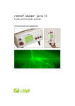
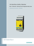
Photonic 500
Two in one
Operation manual
Memory card
Power
Laser
Test
Photonic 500
Stand-by
Ready
Service
Photonic 500
Aux
Contents
1
Views ..................................................................................................................... 4
2
Introduction ......................................................................................................... 6
3
Safety information .............................................................................................. 7
Generelle information
Intended use
Liability disclaimer
Confirmation of function safety standards
Decomissioning in the event of hazzard
4
Safety precautions .............................................................................................. 9
5
Product contents and accessories ...............................................................11
6
Assembling standard ........................................................................................12
7
Applications .......................................................................................................16
8
Start-up ...............................................................................................................18
9
Working with Photonic 500...........................................................................20
Therapy programs
Touchscreen operation
Setting the programs
Adjust the laser beam
Therapy mode
10
The Service menu ............................................................................................36
Functions
Laser function test
Therapy sets
11
Error messages .................................................................................................43
12
Speed of the beam and temperature increase ..........................................45
13
Care and maintenance ...................................................................................46
2
14
Technical description .......................................................................................47
Technical data
Operating conditions
Transport and storage conditions
Guidelines and manufacturer´s declaration
Position of the signs and labels on the device
Description of the labels
15
Guarantee and disposal...................................................................................53
16
Manufacturer, Distributor ...............................................................................54
3
1
Views
11
10
9
8
7
Memory card
Power
Laser
1
Photonic 500
Test
2
Stand-by
3
Ready
Service
Photonic 500
Aux
4
5
6
1
Clear operational mode
See with one view if teh device is ON
in operational mode
6
Comfort buttons
Fast and easy adjustment of the laser
beam, fitting to the treatment area
2
Test sensor for infrared
Practica
Pr
cal test o
ca
off thee functi
tion
onalit
on
ity of
infrared
in
ed probe
bess
be
7
Mains socket/plug
Removable mains plug for transport
3
Fast and easy operation (touchscreen)
Daily wo
Da
work was
as nev
ever thatt easy
ev
sy with
touchs
to
hscr
hs
creen op
operat
ation
at
8
Visible Emergency Stop button
In casee of eme
merg
me
rgency
cy the u
unit ca
can be
shut off
sh
ff immed
edia
ed
iately
ly
9
Remote plug, oor contact
Make tthe
Ma
he treat
atme
at
ment
nt room
m safe
fe and
connec
co
ectt the do
ec
door
or con
ontact
ct
10
Safe against misuse
The ke
Th
keyy protec
ects
ec
ts aga
gainst
ga
unallowe
un
wed usee
we
Visible control lamps
Flashing indicating that the therapy is
ON
4
5
Slot for memory card
Safe for
Sa
or futuree ap
applic
ications
ic
ns and
nd probes
by simpl
ply usingg an u
pl
update vi
via SD card
Connection for laser probes
Addition
Ad
onal pro
on
robe
ro
be can
an be at
atta
tach
ched
at any ttim
ime
11
4
Memory card
Power
1
Laser
Test
Photonic 500
Photonic 500
Stand-by
Ready
Aux
Service
3
2
4
5
6
1
Movable laser head
Allows individual adjustment to any
body area
4
Adjustment of the higth
Place the laser in optimal distance
above the patient
2
Strong holder
Operate the laser head on the holder
5
Safe fixation
Secure the higth with one turn
3
Adjustable Arm
Allows perfect placement for the
treatment area
6
Stable foot
The strong foot with wheels can be
placed stable using the brakes
5
Introduction
2
Your Photonic 500
Two in one
Thank you for choosing the Photonic 500 – the latest generation, high-quality laser device
from Reimers & Janssen GmbH.
The RJ laser design is founded on over 28 years of experience in the development and production of laser devices for medical therapy. Our profound knowledge about complementary therapy methods are built into this product: gentle laser therapy for a broad scope of
applications.
The Photonic 500 involves a base device with a microprocessor, which can control all laser
probes available from Reimers & Janssen GmbH. Thus, the Photonic 500 is the basis of our
trend-setting concept: universal versatility with ease of operation.
Whether you are using surface probes, single probes or laser needles, with the efficient Photonic 500 you will always have the newest therapy program at your disposal.
With the easy-to-use touchscreen and the built-in basic therapy set, you can immediately
proceed with treatment. Every programme can be adapted for your individual therapy needs.
Furthermore, you can purchase special therapy sets and easily install them into your Photonic 500.
Thus, the Photonic 500 is suitable for a wide range of treatments in dermatology, rheumatology, orthopaedics, physiotherapy, sports medicine.
The focussed laser beam of the Photonic 500 can directed as a point, line, or circilary. Such
forms can be changed easily to any larger area to be treated with optimal dosage.
Photonic 500
Two in one
6
Safety information
3
General information
This complete device consists of a drive unit and one or more laser probes that can only be
operated together.
Therefore, before operating your Photonic 500 you must thoroughly read the user manual
for your control unit and the additional user manual of your probe.
The instructions describe the special functions of your Photonic 500. In addition, they describe the commissioning of the device and indicate hazards associated with its use.
All individuals who use, care for, service and supervise this device must read and follow the
instructions.
This user manual must always be kept with the device and must be transferred ownership
along with the laser probe.
Intended use
Your Photonic 500 is an electrical device that is intended exclusively for use in medical
practices and clinics and should only be operated under constant supervision.
This laser device should only be operated by trained medical professionals that have been
instructed in the handling of the device and in the dangers associated with laser radiation as
well as in the compliance with the accident prevention regulation BGV B2 “Laser
radiation” and the DIN EN 60825-1 “Safety with laser equipment”.
Liability disclaimer
You should use your laser probe only for the purposes described in this user manual and
only under supervision!
Repair and maintenance work should also only be performed by Reimers & Janssen GmbH
or an authorized RJ service station.
Before starting thetherapy make sure that the patient is not connected at the same time to
any other electric driven device.
The manufacturer is not liable for the device and the consequences resulting from operation
or applications that are not described within this user manual. The manufacturer
reserves the right to make changes based on technological improvements.
7
Confirmation of function and applied safety standards
The probes conform to the following European safety standards:
•
•
•
•
EN 60601-1: 2007 Safety of medical electrical devices
EN 60601-2: 2007 Electromagnetic compliance
EN 60601-2-22: 2007 Safety of diagnostic and therapeutic laser devices
EN 60825-1: 2007 Safety with laser radiation
Decommissioning in the event of a hazard
If you believe that the device can no longer be operated safely, it should be
decommissioned to prevent against further use and to send it to the retailer
for repair.
Such cases include:
• parts of the housing or the probe cable have visible damage,
• the device no longer functions properly,
• the device is to be stored for a long period under adverse conditions or is to be
transported,
• the display indicator fails or is illegible.
8
Safety precautions
4
Emergency shutdown
Press the red „Emergency Stop“or turn then key swithc to „off“ or remove the remote plug
on teh backside of the housing..
Exercise the handling of the „Emergency Stop“ button to act in case of emergency
rapidly. :Press deeply onto the button until it gets connected, to release the button
turn it gently to the left or right (the button will jump forward).
Treatment room
Operate the laser only indoors. The room in which the laser is located must comply with
the requirements of the Accident Prevention Regulation BGV B2 “Laser radiation”. All
entrances must display a laser warning sign in compliance with EN 60825-1. Reflective
objects, mirrors and chrome surfaces must be removed.
To improve the safety, the user is obligated to connect use door switch to the
Photonic 500. Connect the cable of the door swithg to the „Remote control plug“ of
the Photonic 500. This will lead to an automatic shut down of the Photonic 500 in
case the door of the treatment room was opened during the therapy.
Personnel
The laser should be operated only by trained medical professionals. Personnel must be instructed in the handling of the device and in the dangers associated with laser radiation. The
operator of a Class 3B laser device should have access to a radiation expert or preferably a
radiation control officer who is has professional experience protecting against and controlling the hazards associated with laser, and who will be responsible for the supervision of the
protective measures against the hazards of laser.
Radiation injuries
Avoid direct or scattered radiation to the eyes. Do not look directly into the laser
radiation output area, since visible and invisible laser radiation can cause injury to the eye.
Laser protective eyewear conforming to the European norm EN 207 must always be worn
within the treatment room during treatment. Take precautions when performing therapy in
the head region!
9
When treating patients with darkly pigmented skin, birthmarks, tattoos, etc, be aware that
there is a risk of burning because melanin or colour in the skin tissue absorbs the light
Reduce the power or energy output with pigmented skin.
Risk of infection
Use your probe for therapy of patients only in areas with intact skin, because there is a risk
of infection through contact transmission of germs.
After each treatment, disinfect your probe as described in the chapter Care and Maintenance. If you use an applicator, disinfect the applicator after each treatment in order to minimize the risk of patient infection.
Risk of burning
With high power output and longer treatment times, the probe tip can overheat. In this
case, avoid direct skin contact by using a cap or applicator; otherwise you may burn the skin.
Alternatively, reduce the power output or treatment time.
Prevent unauthorised use
The Photonic 500 is equipped with a key switch to prevent unauthorised use. The laser can
be operated only with the key inserted.
When the laser is not in use, the key should always be removed and stored separate from
the unit in order to prevent unauthorised use.
Registration
Operators of a Photonic 500 unit must be registered as an operator of a Class 3B laser
device with the professional association prior to the first commissioning of the device.
10
Product contents and
accessories
5
Delivery contents
the Photonic 500 will be delivered partly
monted in 3 parcels.
Parcel 1, foot od the stand
•
•
•
•
•
•
•
Foot with power supply GlobTek
GTM21097-5012-2.0 – 10V/4.7A,
connection cable, 2 cable holders
Mains current supply cable
4 wheels (2 with brakes)
Tripod arm, with holder
2 laser protection googles
Warning sign „Laser Irradiation“ acc. to
DIN EN 60825-1
Parcel 2, tripod main tube
•
•
Main tube
Butterfly screw with disc
Parcel 2, laser head
•
•
•
Laser head
2 keys
1 remote plug „REMOTE LASER STOP“
Reimers & Janssen GmbH supplies a large
range of laser probes which can be connected to the Photonic. Please contact your
supplier for more details.
Therapy programs
Beside the installed “Therapy Basic Set” you
have the choice to select more frequencies
and therapy programs. For new developments contact your supplier.
11
6
Assembling the stand
The Photonic 500 can be assembled within a few minutes, no extra tools are required.
Please note that the main tube of the tripod contains a pressure spring. It can be dangerous if you release it in compressed state (internal tube jumps up!).
2
1
Place the foot upside down and attach the 4 wheels
deeply into the holes until they connect. Wheels with
brakes should be placed on one side (not in opposition)
Thereafter place the
foot to the ground and
secure withthe brakes
for better mounting.
3
The internal main tube shoud be fixated with the screw (knob).
12
4
5
Insert the main tube
into the opening on
the foot and turn it
until it snaps into place.
Secure with the butterfly screw (do
not forget the disc)
6
Insert the arm (open tube
side) into the main tube of
the stand. The hole of the
arm should be placed above
the hole of the main tube.
Secure it with the handle
bar.
7
Before attaching the laser head, please draw
down the metal knob approx. 1 cm until it
stops. Now you can insert the tube of the arm.
13
8
Now place the Photonic
500 drive unit on the
boom and push it as far
over the bar until the pin
engages in the laser head
in the hole on the underside of the bar. Make sure
that the Photonic 500
drive unit horizontal in
order to engage the pin.
9
Memory card
Power
Laser
Test
Photonic 500
Stand-by
Ready
Service
Photonic 500
Aux
Plug the cable of the power supply to the socket Photonic 500 drive unit at the rear
and secure it by tightening the nut.
Attach the cable to the tripod attached with cable ties.
10
When you insert the power plug on Photonic 500 is operational. In order to start,
turn the key.
Please read as well the chapter
„Starting the device“ on page 18.
14
Changing the inclination of the Photonic 500
If want you adjust or turn the Photonic 500 drive unit, please loosen the handle/screw on
the hinge and move it the handle into the desired position. The width of the angle is up to
45 ° upward from the horizontal position.
Memor
y card
Power
Laser
Test
Photon
ic 500
Stand-by
Ready
Service
Photon
ic 500
Aux
Rotate the laser head
If you want that the laser beam radiates sideways, you can simply turn the head and rotate
about its own axis. Up to 90 ° in both directions are possible. Thanks to a self-retaining joint,
the head remains stable in any new position.
ory
Mem
card
Aux
wer
Po
Test
r
Lase
For heigth adjustment, please use only the handle on the tripod, not the handle on
the laser head, otherwise you may damage the housing.
15
Applications
7
Treatment range
The Photonic 500 can be used for a wide range of treatments in dermatology, rheumatology,
orthopaedics, physiotherapy, sports medicine and veterinary medicine as well as dentistry. It
is especially designed for complementary medicine and acupuncture and auricular medicine.
On your Photonic 500 control unit there is a variety of individually adjustable therapy programmes. If you would like an overview of all currently available therapy programmes and
frequencies, please contact your retailer.
Your Photonic 500 may be used for radiation of the skin and for acupuncture treatment.
Indications
The following indications qualify for effective treatment on the body:
• bone healing
• wound healing
• pain
• synovitis / tendinitis
• rheumatic diseases
The following indications qualify for aPDT/PAD at 632-670 nm:
• alveolar ostitis
• general caries
• endodontics
• parodontitis
• periimplantitis
• pain reduction in multiband therapy
• wound healing following extraction and implantation as well as surgery
• treatment of gingival pockets
16
Limitations
As manufacturers we advise against the radiation of the following organs and areas:
• eyes
• areas near the thyroid gland and other endocrine glands
• testicular regions
• epiphyseal regions in children
• open fontanel
• foetuses or in the areas over the uterus of pregnant women
• dark, pigmented or coloured skin, regions with dark hair
• non radiation in the head area in patients with (tendency for) epilepsy
In addition, we advise against treatment of patients with the following indications:
• patients with a pacemaker
• cytostatic immunosuppression
• tumour/cancer patients
17
Start-up
8
Testing for damage during transport
Begin by testing your probe for damage that may have occurred during transport, i.e. whether the housing components or the probe cable have visible damage. If you have a probe
with a display, remove the protective cover from the display and test the indicator. If you
discover any damage, do not operate your probe. Instead, contact your retailer.
Place the unit
Select a stable even surface/table and secure the tripod wheels. Conenct the device to the
mains current via the power supply.
Safety plug temporarly opened
Check if the „Remote control plug“ is connected with a plug. Now you are able to work
without door contact and can secure the usability of the device. If not, insert the plug.
You can us the socket for a door contact.
Connecting Probes
If you have purchased your Photonic 500 along with a new probe, please read the accompanying probe user manual. Activate your probe accordingly, and connect it with the appropriate probe cable to socket „Aux“ on the front panel.
Memory card
Photonic 500
Ready
Service
Photonic 500
Aux
18
Teh After switching ON with the Key-switch, the power indicator will glow and the touch
screen will show the message „power on self test”. Thereafter the booting of the Photonic
500 software will begin.
If the power indicator does not illuminate and the touchscreen remains dark, the “emergency stop” button may have been pressed. If that is the case, please unlock the emergency
shutdown, by turning it slightly to the left or right, until the switch moves a few millimetres
upwards to the stand-by position. If the device remains unresponsive, please determine whether the power adaptor has been connected correctly.
STAND BY / READY Mode
After booting the software will go into stand-by mode. no you can use the Photonic 500.
Memory card
Power
Laser
power on self test
Photonic 500
Test
Schlüsselschalter
Aux
Zum Schutz gegen unbefugtes Benutzen ist der Photonic 500 mit einem Schlüsselschalter ausgestattet. Stecken Sie den Schlüssel in das Schloss und drehen Sie ihn auf ON. Die
19
Working with the Photonic 500
9
Therapy programs
This user manual describes the basic
functions and safe practices of the Photonic
500 with respect to the standard pre-set
therapy program “Basic therapy”.
Other therapy sets that can be purchased
function basically in the same way. However,
please note that some probes, for example
the LightNeedle probe, offer additional
setup possibilities. Therefore, please read the
user manual for your probe as well.
Automatic probe detection
The Photonic 500 automatically detects
the connected probe without you having to
worry about a special installation. If you later
purchase a new probe, you must simply
update the Photonic 500 software.You can
carry out this update quite simply using one
of the SD cards included with the probe. A
manual will also be included.
For ease of determination,
particularly in dual probe operation,
each probe type is indicated in the
therapy programme with a special
symbol. The symbol for your probe
can be found in the accompanying
user manual.
You can use single and multi-cluster probes
for your Photonic 500. Please refer to the
probe manual.
20
Touchscreen operation
After you have initiated your Photonic 500
with your probe as described in the previous chapter, all the functions and setup
possibilities are available on the easy-to-use
touchscreen.
Pressing the “Ready” button takes you directly to the Therapy Programmes. Pressing
the “Service” button takes you to the basic
settings mode (see page 24).
The “Stand-by” screen display always
appears after you first turn on the device.
Please touch the touchscreen only
with a finger or special stylus, never
with a hard or pointy object!
Even if you use several probes or
purchase additional ones, the touchscreen operation basically remains the
same.
A variety of Reimers & Janssen probes are
available for different applications using this
simple operation concept.Your Photonic
500 software can be easily updated, so you
are best equipped for future possibilities in
laser therapy.
21
Therapy selection display
Pressing “Ready” in the “Stand-by” display
takes you to the therapy selection screen,
where you can choose your therapy programme. In the standard configuration, the
programme set “Basic Therapy” is the preset default.
If you have purchased additional programme
sets, they will be indicated as “pages” in the
therapy selection screen. In the following
sample screen images, the setup and functioning relate to the Basic Therapy programme.
If you have correctly connected your probe,
a symbol corresponding to “Laser 1” or “Laser 2” will appear on the button in the therapy selection screen. “Laser 1” corresponds
to the laser in the Photonic 500 and “Laser
2” to the socket for laser probes.
Therapy selection screen with the pre-set
“Basic Therapy” programme.
Functions that are active or activatable are
shown in yellow on all screens.
Adapting the programme
You can customize the pre-set therapy
programme for your own needs with your
Photonic 500.
The power, energy output, and time parameters can be adjusted. Except in continuous
wave operation, you can change the frequency of the laser beam or combine with
a second frequency using “edit”. For better
orientation you can also re-define the programme buttons.
The exact procedure is described in the
following pages.
Therapy selection screen with the symbol
for a point probe with 150mW power. The
therapy time pre-set in programme “F2” is 5
minutes with an energy output of 22 Joules.
Most probes offer the possibility to
begin therapy directly with the probe
at the pre-set values. However, do
not forget to protect yourself and
your patient with laser protective
eyewear.
22
Editing the parameters
In the “continuous wave” therapy mode
selected this example, the “power/energy/
time” button indicates a total power output
of 150mW, energy output of 45 Joules and
treatment time of 5 minutes.
If you wish to change these parameters,
please press this button. The “Laser settings”
screen will appear and here you can edit the
individual parameters and the pitch of the
signal tones.
Parameter button (circled) on the therapy
selection screen
The power cannot be changed with
superpulsed lasers.
“Laser settings” screen
Entering the changes
In this example, if you wish to increase the
energy output to 90 Joules, please press
the “Energy” button and enter “90” on the
keypad. The therapy time will automatically
change to 10 minutes. Confirm your selection by pressing “Enter”.
It is easier to make your selections
with the tip of a pen rather than a
finger. However, ensure that the pen
tip is retracted.
“Laser settings” screen with numeric keypad
23
Automatic changes
The other parameters can be changed in the
“Laser Settings” screen in the same way.
If you change the power, the therapy time
adapts automatically, and similarly, if you
change the therapy time, the energy output
is automatically calculated and indicated.
Entering therapy time: to enter the seconds,
press the colon (circled) following the
Saving your changes
The software offers the possibility to permanently save your changes.
With the “Save individually” option, you
have the choice to save changes only for
the current selected therapy programme or
with “Save for all”, you can save the changes
permanently for all programmes in the therapy set.
Pressing the “Factory settings” button returns all the parameters in the therapy set
to the standard pre-set values.
The changes for the currently selected
therapy programme are saved permanently
by pressing the “save individually” button
(circled).
You are returned to the therapy selection screen after saving or re-setting the
parameters.
To prevent inadvertently selecting
“Save for all” or “Factory settings”
for other therapy programmes, there
is always a confirmation requested.
Confirmation screen to protect from
inadvertent changes.
24
Return to therapy selection
Some probes have their own display on
which the settings for the therapy programme are indicated. If this display is difficult to
read, for example in bright sunlight, you can
change the contrast of the display using the
“Contrast” button.
If you are finished with the settings and do
not wish to save them, return to the therapy selection directly using the “Therapy”
button.
Pressing “Therapy” (circled) returns you
directly to the therapy programmes.
From there you can begin a therapy with the
adjusted parameters. After the treatment,
the settings are automatically reset.
If you wish to edit the programme or switch
to a different programme before starting the
therapy, the settings will be lost.
Editing the programme
Except in continuous wave operation, you
can also change the laser beam frequency
or combine with a second frequency if you
wish.
For a blank template, you have the option
of giving a new name to the programme,
for example, for various indications, therapy
times, or special frequencies.
Therapy selection screen with the “Edit”
button
All functions can be retrieved using the
“Edit” button.
Mixing and changes frequencies
This takes you to the “Edit frequency”
mode, where in our example at first only a
pre-set 1500 Hz frequency is active.
“Edit frequency” screen
25
2. Combining frequency
Pressing the “Activate/deactivate second
frequency” button adds a second frequency
of 2000 Hz.
The powerful Photonic 500
offers a frequency range from
1-99,999 Hz for continuous wave
probes. Superpulsed probes allow
up to 40,000 Hz.
2. Frequency is activated
Changing the frequency
If you wish to change the frequency, simply
press the corresponding frequency button
and enter the desired Hertz value on the
numeric keypad.
If you increase the frequency for a
superpulsed probe, the energy
output will automatically increase for
the same treatment time. Lowering
the frequency reduces the energy
output.
“Edit frequencies” screen with the numeric
keypad.
Designating a name
Pressing the “Designate a name” button
opens a popup window to enter a name. Do
not enter an extra long name, or the name
will appear smaller in the single line in the
therapy selection window.
The input screen works like a typical cell phone input screen.You can
select between lower- and uppercase letters and between letters or
numbers. This gives you flexibility in
naming your therapy programme.
“Edit frequencies” screen with field for
the name for uppercase letters (circled on
ABC) and switch to lowercase. A space is
entered using the “0” button.
26
Return to therapy selection
In this example, two individually set frequencies are combined for the treatment of
carpal tunnel syndrome and the programme
is given the name of the indication being
treated.
You return to the therapy selection screen
using the “Therapy” button.
Pressing “Therapy” returns you immediately
to the therapy selection screen.
Begin therapy
Probes equipped with their own “start/stop”
button allow you to begin treatment directly
from your probe.
Before therapy mode begins, there is a twosecond tone.
During this time, you can still press “stop”
to end the programme, for example if you
have forgotten to put on protective eyewear.
The “Therapy selection” screen with custom-named therapy programmes.
27
Beam size and form
By touching the button „Start“ to open the
screen „Adjust Photonic“. At the same time
the pilot will start. in order to see the real
beam size/form.
Only during the first setup because of e.g.
new software you have to go via „Start“ to
the next screen „Adjust Photonic“ (next
page).
With „Start“ you willr each directly the
screen „Adjust Photonic“.
Adjust the beam size and form
In the screen „Adjust“ the leaser beam can
be configurated according to pre-setted
forms. It will always appear the last selected
form and individual settings.
Inorder to get to know the Photonic 500
please have a look at first to the different
forms. Select it witht he buitton which
shows the forms.
Pressing the button whoch shows the
geometrical forms will lead to the menu.
Test the beam size selection at first
without patients.
28
Static and movable forms
On the screen „Select Form“ you can choose between stable/fixed and three movable
forms.
The fixed forms offer a circle, a vertical/horizontal line and a point.
The movabale forms offer a filled circle
(oscillation) a square (the line moves up and
down on an rectangle).
Once you tip to the form you will reach
the screen „Adjust Photonic“, where you
can change the basic form and speed of the
movement.
On the screen „Select Form“ you will find
the fixed/stable forms in the upper line and
the movable forms in the lower line.
Please note that the form „Point“
will generate heat and this can lead
to overheating the skin, especially
pigmented skin: Reduce the power
and treatment duration!
29
Change expansion
On the screen „Adjust Photonic“ you can
change the amplitude/size.of all forms except the point.
With the arrow buttons you can change the
size of the form for horizontal orvertical,
dimension. For example you may change
the circle to an ellypse.
The pilot beam (<5mW) control lamps on
top of the housing will be active during the
setting.
The screen „Adjsut Photonic“ with active
„amplitude“ function. The circle was stretched vertically.
In pilot beam mode you can adjust
the size and form without protection
goggles. before you start the therapy
Change position
Move the position to different areas without
moving the housing with the arrow buttons.
Reset will jump back to normal.
Active „Position“ allows to move the form
to laft or right.
30
Movable forms
Movable forms can be adjusted in the
amplitude, position and speed (press button
„Speed“).
Please use the plus/minus buttons to imcrease or decraease the speed of the laser
beam.
With „+“- and „-“ the speed of the laser
beam movement can be changed.
Turning knobs
Instead of the arrow buttons you can adjust
all features with the turning knobs. this is
probably much faster and easy to do.
Once you have selected „Amplitude“ or
„Position“ the knob will change vertical and
horizontal. axis
In case the „Speed“ is active, the knobs offer
the same function as above.
Left turn slows down and right turn increases the speed.
Photonic 500
Aux
The left button will change the form in regard to the Y-axis and the right knob the
X-axis.
The knobs do not have a setting
for the middle position, Left or
right always refers to the current
selection.
31
Function of arrow buttons, turning knobs
Memory card
Power
Test
Photonic 500
Stand-by
Ready
Service
Photonic 500
Aux
Y-Achs
e
Laser
X-Achse
Active
Function
Vertical button
Amplitude
Upper:
vertical stretch
Lower:
vertical upsetting
Upper: move up
Position
Lower: move
down
Upper: increase
Speed
lower:
decrease
refers to left
knob
Turn right
Trun left
Turn right
Turn left
Turn left
Turn righ
Horizontal button
refers to right
knob
Left:
Turn left
horizontal upsetting
Right:
Turn right
horizontal stretch
Left: move to the
left
Right move to the
right
Left:
slow down
Right:
speed-up
Turn left
Turn right
Turn left
Turn right
32
Reset individual settings
With „Reset“ you can get back to the original settings.
Your Photonic 500 „memorizes“
the forms. After restart the device
will always keep the last settings.
With „Reset“ (circle) all individual settings
will be deleted.
Start the therapy
After all forms are selected start the therapy with the button „Start“.
Prior to the start of the laser beam a two
signal (beep) will indicate that the laser now
will be in use.
You can „Stop“ the start e.g. in case if someone, forgot to waer goggles.
With the button „Start“ the laser beam will
be activated with presetted power and time.
33
The therapy mode
Prior to the therapy please wear
protection goggles!
After the beep, the theraapy screen appears
with the treatment programs and all the set
parameters.
During the therapy, a short beep will be
announced every fifteen seconds. The timer
will count down to zero, and the administered amount of energy increases.
A long beep will be announced once the
therapy time is reached. The current treatment can be aborted at any time by pressing
„stop“.
Upper yellow part of the therapy screen
shows the active laser with all settings.
Lower part remains blue because no probe
was connected.
During the treatment googles must be worn
by staff and patients. Only goggles that are
marked according to EN 207 may be used.
The effective wavelength range of the filter
lenses must include the wavelength of the
Photonic 500 and connected probes.
For details regarding the correct googles, pelase contact RJ-LASER or your
supplier.
34
Additional probe
With your Photonic 500 you can use addional probes simultaneously with individual
settings. In case you change the probes inbetween, the old settings for each probe will
be memorized.
You even can attach a probe during therapy.
The therapy screen will accur to start the
probe (use the start button on the probe).
Generally all settings of the probe and main
unit are similar. Changes can be made on the
active yellow propbe.
Screen for Therapy mode „BASIC“, active
main unit and without probe.
In case you want to use an additional
probe, you must start the Photonic
500 drive unit (laser) at first.
Photonic 500
Aux
The socket „Aux“on the front panel is reserved for the probes.
35
The service menu
10
Functions
The software architecture of your Photonic
500 is so simple that you are immediately
ready to begin working with it as soon as
the device is turned on by selecting the
“Ready” button.
You should need to access the functions of
the service menu only if you wish to change
the basic settings of your Photonic 500 – e.g.
language, energy saving mode, or key clicks –
to your own particular needs or to do special test functions or to update the software
with a new probe.
Use the „Stand-by“ button to back to the
„Stand-by“ screen and from that to service.
In the following pages, the functions of the
service menu are briefly explained step-bystep. Access always begins by pressing the
“Service” button on the “Stand-by” screen.
The „Stand-by“ screen appears after the
unit was started (key switch).
36
Setup Set 1
You will find all the basic functions and settings in three sets on the “Setup” screen
In general, Set 1 is activated with the language choice, version indicator, key click setting
and the laser test is activated at the start.
Here, you can change the language of the
software of your Photonic 500.
Version indicator
Under “Version” you will find information about the hard- and software version
of your Photonic 500 and any connected
probes.
This information can be important for the
service technician, for example because
a problem can occur with the operation
of a new probe with outdated operation
software.
Reimers & Janssen are constantly updating
the hard- and software so that your device
is always up-to-date.
The sequence of the software version is
indicated numerically, so in this example the
Laser 2 software is “PN220110A” from
January 22, 2010.
“Programme” indicates the operation
software.
Key clicks
The intuitive touchscreen operation is
supported by an acoustic feedback feature.
However, you can deselect this accessibility
option.
Key clicking is set to “on” in the basic
settings.
37
Laser function test
The “Laser test” function assists users who
wish to operate an infrared laser probe on
their Photonic 500, by testing the proper
functioning of this probe.
Please activate the “Laser test” for this and
select “on”. Then start your probe in the
therapy selection screen and immediately
hold the laser outlet in front of the “Laser
test” sensor on the front of your Photonic
500.
You can change the sensitivity of the sensor
with the “-” and “+” for a “Laser test”.
If the laser is functioning properly, there is
a signal tone. If this is not the case, increase
the sensitivity of the sensor in the Service
Menu and repeat the test.
Memory card
If a signal is heard before the laser
beam is held in front of the sensor,
please reduce the sensitivity. It could
also be that too much sunlight is
hitting the sensor, in which case you
should move your device or darken
the room.
Power
Laser
Test
Photonic 500
Stand-by
Ready
Service
Photonic 500
Aux
„Laser Test“ sensor on the front panel
38
Setup Set 2
Your Photonic 500 has built in rechargeable
batteries so you can easily perform therapy
in the field (see “Mobile use” on page 31).
In order to extend the operating time you
can save energy by setting the screensaver
to activate sooner.
The screensaver activates after 10 minutes
of inactivity in the basic settings.
Power indicator
The power indicator indicates how long the
Photonic 500 has been operated in therapy
mode.
The power indicator screen
39
Error protocol
You can use the “Logging” function to save
the protocol data to an SD card while the
device is operating.
This can help a service technician to detect
errors that arise during operation that have
no obvious cause.
The “Logging” function is displayed in the
basic settings.
Before engaging the “Logging”
function, your must insert an SD card
into your Photonic 500. Please ensure
that the contact tabs are aligned from
below and that the tapered edge
points inward. A correctly inserted
card will be indicated by a corresponding symbol in the Stand By screen.
e
arg
Ch
s
nosi
Diag
Software update
When you connect a new probe or
purchase a new therapy you might be required to perform a software update.
Insert the SD card into the memory card
slot on your control unit until it clicks.
Existing therapy sets are overwritten
during a software update. If you have
entered changes which you wish to
retain, save your therapy programme
beforehand (see relevant page).
You will automatically receive detailed
instructions for a software update with
a new SD card. If you already have an
SD card, you can also receive this update conveniently by email.
Please contact your manufacturer or retailer
for a software update.
40
Setup Set 3
With the open software architecture of
your Photonic 500 olympic, you can always
work with the therapy programmes that
are best adapted for your applications and
which are based on cutting-edge research.
In addition to the “Basic Therapy” set,
you can acquire additional therapy programmes for your particular configuration from your retailer. Please enquire
about the current developments with
your retailer.
In the “Set 3” screen, you can select and
deselect the therapy sets and save them
externally or on an SD card.
Activate the therapy sets
You can certainly use several programme
sets at the same time. In “Set 3”, all the therapy sets available on your Physiolaser are
indicated, from which you select or deselect
for the given situation.
In this example, only the “Basic therapy” set
is activated. If you wish to add additional
sets, these will be carried over into the
therapy selection screen.
41
Backing up the therapy sets
Your Photonic 500 allows you to save
complete therapy sets on an SD card or to
transfer them from an SD card to the control unit. This may be important, for example, if you have customized your programme
and do not want to lose these modifications
during a software update.
Existing therapy sets with the same
name will overwrite each other during saving or downloading without
requesting confirmation. Therefore,
back up your therapy sets prior to a
software update, since an update will
overwrite existing therapy sets.
Pressing “Save” (circled) stores the selected
therapy set on an SD card.
Therefore, it is best to use an extra SD
card without software updates and insert
this into your Photonic 500 as described on
page 28.
Then select “Therapy sets – back up” and
activate the sets that you wish to save. As
soon as you press “Save” the selected sets
are then automatically saved onto the SD
card.
Downloading therapy sets
If you wish to download therapy sets onto
your control unit again, please select
“Therapy sets – download”. Sets available
on the SD card will be shown. Activate the
sets that you wish to install and then press
“Download”. The selected sets will now be
downloaded automatically.
Please be aware that the existing
therapy sets with the same names
are overwritten during saving and
downloading without requesting
confirmation.
Pressing “Therapy sets – download”
downloads the selected therapy sets from
the SD card onto the Photonic.
42
Error messages
11
Starting over after error message
Your Photonic 500 uses a sophisticated and
stable software design so that error messages should occur only very rarely.
In some circumstances an error can be corrected by a simple re-start.
If the error message re-appears, please contact your retailer.
If repair work is required, your retailer can
provide you with a replacement if necessary.
Confirm the message with “OK” and turn of
your Physiolaser. Wait a moment and then
turn the device back on.
Opening the safety interlocking
mechanism
If the “Remote control plug” loosens or is
unplugged, a corresponding error message
will appear and all probes are deactivated.
In order to continue working, you must
re-insert the plug.
43
Critical errors
If critical system errors occur and the error
message depicted in the illustration appears,
please turn off the device and contact your
retailer.
If repair work is required, your
retailer can provide you with a
replacement if necessary.
Critical error: Please disconnect all laser
probes and turn off the device.
Critical error: Please disconnect all laser
probes and turn off the device.
44
Speed and temperature increase 12
Therapeutic options
With your Photonic 500 you can select and irradiate geometric forms in order to treat the
body in correct dimension fitting to the body part. Additionally you can determine the speed
of the movement of the beams.
By means of this innovative options you may apply more therapeutic effect: If you want a
more point orientated therapy, slow down the speed this will bring more heat to the body,
in case you want less heat, simply reduce the speed. The supplied energy remains the
same!
Temperature
Temperatur
(an einem Punkt)
(at a point)
Time
Zeit
0
Temperature at low speed: More heat because the laser remains a longer time on a point.
Temperature
Temperatur
Punkt)
(at(anaeinem
point)
Time
Zeit
0
Temperature bat high speed: Less heat because the laser moves faster from point to point.
point.
45
Care and maintenance
13
Cleaning and disinfection
Unplug the power cord of the Photonic 500 before beginning all cleaning and care!
Please ensure that you do not use sharp or caustic agents (e.g. acetone) when cleaning the
plastic parts. Avoid getting moisture in the housing. A damp cloth is the best cleaning tool.
To disinfect the device, use a soft cloth that has been dampened with a mild e.g. DGHMapproved [DGHM=Deutsche Gesellschaft für Hygiene und Mikrobiologie=German Hygiene
and Microbiology Association] disinfecting agent.
Always use a damp cloth for cleaning and disinfection – never flush water over the
device. Do not use a solvent!
If you work with an applicator, sterilise the applicator after each use in order to avoid
transmitting infection to the patient.
Calibration and safety check
Your Photonic 500 does not contain internal parts or components that need to be serviced
by the user. Thus, there is no reason to open the device housing.
In order to comply with the regulation EN 60825-1 “Safety in laser facilities”, your Photonic
500 unit, along with all probes and accessories, should be sent to the manufacturer for checking and recalibration no longer than one year after you begin to use it.
Please be aware that the annual safety check is mandatory and is legislatively prescribed by the Medical Devices Act (in Germany, MPBetreibV §6). Please contact your
retailer.
46
Technical description
14
Technical Data
Laser therapy device cl. 3B
Photonic 500
Protection class
IPXO
Absolute failure of the the power
measurement
+/-20%
Modulation frequency
0,1 Hz bis 99999 Hz
Accuracy of the impedance measurement
+/- 10%
Risk class according to RL 93/42/EWG
IIa
Power supply with battery charge
Globtek GTM21097-5012-2.0 –
10V/4.7A
Mains voltage = 100-240V~
Mains frequency = 50-60Hz
Output current = 400mA
Protection class II
Weight
4 kg
Dimension drive unit (L x D x H)
50 cm x 20 cm x 15 cm
Operating conditions
Room temperature
+ 10°C bis +30°C
Relative humidity
30% bis 75%
Atmospheric pressure
700 hPa bis 1060 hPa
47
Transport and storage
Room temperature
-20° C bis +40 C
Relative humidity
30% bis 75%
Atmospheric pressure
700 hPa bis 1060 hPa
Laser-Diodes
Quantity
Wavelength
Power
Laser typ
NOHD*
Beam divergence
1x red
638 nm
max. 150 mW
Continuous
beam (CW)
> 10 m
3 mrad
1x infrared
810 nm
max. 500 mW
Continuous
beam(CW)
> 10 m
3 mrad
LED-Diodes
1 diode green, 1 diode yellow,
1 foto sensor diode
Quantity
* Safety margin (NOHD): The distance at which the radiation strength or the radiation is equal to the corresponding limit for the maximum permissible
radiation of the cornea (MPE=Maximum Permissible Exposure).
Guidelines and manufacturer’s declaration – Electromagnetic radiation
Conformity
Electromagnetic ambient conditions - guideline
HF-radiation to
CICPR 11
Group 1
The laser device uses HF-energy only for its
internal function. Therefore HF radiation is
very low. The influence on neighbouring electric devices is unlikely
HF-radiation to
CICPR 11
Class B
Radiation of harmonic
oscillation according
to IEC 61000-3-2
Conforms
Radiation of voltage
variations/ Flicker
effect according to IEC
61000-3-3
Conforms
Radiated disturbance
measurements
The laser device may be used in all kinds of
buildings, including residential buildings and
those directly connected to mains for the
public supply which are also servicing buildings used for residential purposes.
48
Guidelines and manufacturer’s declaration - Electromagnetic immunity
IEC 60601-test
level
Conformity
level
Electromagnetic ambient conditions - guidelines
Discharge of
static electricity (ESD )according to IEC
61000-4-2
± 6 kV Contact
discharge
conforms
The floor should be made from
wood or concrete or covered
with ceramic tiles. If the floor is
covered with synthetic material
the relative humidity should be
minimum 30%
Fast transient
electric disturbance variable
/ Bursts
according to
IEC 61000-4-4
± 2kV
for network
leads
conforms
The quality of the supply voltage
should be typical for business or
hospital ambient conditions
Pulse voltage
(Surges) according to IEC
61000-4-5
± 1 kV
opposed mode
voltage
conforms
The quality of the supply voltage
should be typical for business or
hospital ambient conditions.
Immunity tests
± 8 kV Air discharge
± 1 kV
for input and
output leads
± 2 kV
common mode
voltage
Voltage dips,
short interruptions
and voltage
variations according to IEC
61000-4-11
< 5% UT
(> 95% dip of
UT) for ½ period
40% UT
(60% dip of UT)
for 5 periods
70% UT
(30% dip of UT)
for 25 periods
< 5% UT
(> 95% dip of
UT) for 5 s
conforms
The quality of the supply voltage
should be typical for business or
hospital ambient conditions. If the
user wants to continue operation
in case of an interrupted energy
supply it is recommended to feed
the laser device from a system
without interruption or a battery.
Magnetic field at
supply freq. (50/60
Hz) according to
IEC 61000-4-8
3 A/m
conforms
Magnetic fields at mains frequency
should have the typical values for
business and hospital ambient
conditions.
Note: UT - alternating voltage mains before the application of the test level
49
Guidelines and manufacturer’s declaration – Electromagnetic immunity –
for the laser device without life supporting function
Immunity tests
HF-disturbance variables (transmission) according
to IEC 610004-3
IEC 60601test level
Conformity
level
Electromagnetic ambient conditions guidelines
3 Veff
150 kHz bis
80 MH
conforms
Portable and mobile radio sets must
not be operated in a distance to the
laser device and the leads less than the
recommended protective distance what
was calculated according to the equation for the transmission frequency.
Recommended protective distance:
d = 1,2 √ P
d = 1,2 √ P for
80 MHz up to 800 MHz
HF-disturbance variables (radiation)
according to
IEC 61000-4-3
3 V/m
80 MHz bis
2,5 GHz
conforms
d = 2,3 √ P for
800 MHz up to 2,5 GHz
with P as power rating of the transmitter in Watt (W) according to data from
the manufacturer of the transmitter
and as recommended protective distance in meter (m).
According to a local a investigation
the field intensity for all frequencies of
immobile radio transmitters should be
less than the conformity levelb.
Interference is possible in the surroundings of devices carrying the following
signs.
Note 1
At 80 MHz and 800 MHz the higher frequency range is applied.
Note 2
These guidelines are not applicable in all cases. The propagation of electromagnetic quantities is influenced by the
absorption and reflection of buildings, items and human beings.
a
It is not possible to predict theoretically the field strength of immobile transmitters like base stations of mobile
phones and mobile land radio sets, amateur radio stations, AM and FM television and radio broadcasting transmitters. In order
to determine electromagnetic ambient conditions with regard to immobile transmitters a study of the location should be taken
into consideration. If the field strength measured in the place where the laser device is operated exceeds the above mentioned
conformity level the laser device should be watched to proof its function in accordance to the requirements. Unusual performance data may require additional measures, for instance change of orientation or different location of the laser device.
b
Above the frequency range from 150 kHz to 80 MHz the field strength should be less than 3 V/m.
50
Recommended protective distance between portable and mobile HFtelecommunication devices and
the laser device without life supporting function
Recommended protective distance between portable and mobile HF-telecommunication
devices and the laser device
The laser device is designed for the operation in electromagnetic ambient conditions
where HF-disturbance variables are controlled. Client or user of the laser device can
help to avoid electromagnetic disturbances by keeping the minimum distance between
portable and mobile HF-telecommunication devices (transmitters) and the laser device as
indicated below, dependent on the power output of the communication device.
Power rating of the
transmitter W
SProtective distance dependent on the transmitting frequency m
150 kHz to 80 MHz
d = 1,2 √ P
80 MHz to 800
MHz
d = 1,2 √ P
800 MHz to 2,5
GHz
d = 2,3 √ P
0,01
0,12
0,12
0,23
0,1
0,38
0,38
0,73
1
1,2
1,2
2,3
10
3,8
3,8
7,3
100
12
12
23
If the maximum power rating for certain transmitters is not given in the above table the recommended
protective distance d in metres (m) can be determined by using the equation indicated in the respective column,
where P is the maximum power rating of the transmitter in Watt (W) according to the manufacturer of the
transmitter.
Note 1 At 80 MHz and 800 MHz the higher frequency range is applied
Note 2 These guidelines are not applicable in all cases. The propagation of electromagnetic quantities is
influenced by the absorption and reflection of buildings, items and human beings.
51
Position of the labels on the device, description of the labels
5
ory
Mem
4
card
1
Aux
we
r
Po
2
Test
r
Lase
6
3
1. Laser warning sign
2. Laser warning sign
3. Laser outlet
Symbol for the laser beam: “Warning for
laser beam”. Aiming of laser beam must
be adhered to avoid any other part of
the body other than the treatment area
follow treatment protocol of this manual.
4. Power
5. Type plate
6. Laser warning sign
Remote control plug next to the plug
Explanatory label (International):
„Laser radiation“
Laser outlet
Type plate below
0123
IPX0
The device meets the require-ments
of 93/42/EEC for medical products.
No rating against harmful ingress of
water as defined in IEC529
“Attention” Observe the
instructions in the manual for safe
and effective usage of this device.
Protection against electric shock
regarding allowable leakage current
limitations are specified in standard
60601-1.
Production date, month - year
52
Guarantee and disposal
15
Guarantee
The manufacturer’s guarantee is valid for 24 months. The manufacturer is only responsible
for the features warranted by the user manual, if the device has been operated carefully
according to the user manual.
Readjustment, calibration and maintenance or repairs should only be performed by the
retailer, otherwise the guarantee expires. Any alterations or interventions on the device by
an unauthorized third party void the guarantee. The manufacturer guarantees replacement
parts for a period of ten years after the date of purchase.
Disposal
Probes and control units may not be disposed of along with normal electronic waste because of the radiation hazard. The devices should be sent to the manufacturer for decommissioning and disposal.
53
Manufacturer / Distributor
16
REIMERS & JANSSEN GmbH
Photomedicine — Laser Therapy
V. 1.1,
Fabrikstr. 22
Tel. +49-7681-4934149
[email protected]
79183 Waldkirch, Germany
Fax +49-7681-4934150
www.rj-laser.com
Quality Management
ISO 13485: 2003 + AC:2009
25.05.2012
Distributor
54