1
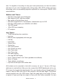
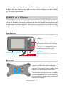
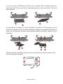
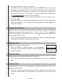
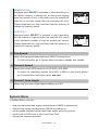
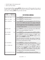
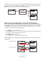
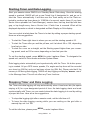
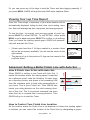
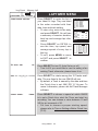
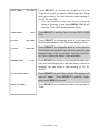
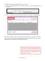
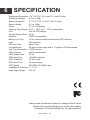
JI100 SERIES USER MANUAL
Version 0421 2014
SpeedAngle Inc.
www.SpeedAngle.com
IMPORTANT! PLEASE READ!
SpeedAngle Lap Timer is a device with high technology and powerful algorithm. It is
capable of calculating and producing lean angle measurement real time, and then listing
the results in the Angle History and the Max Angle fields. However, there are times when
the real time lean angle measurement might be exaggerated, such as when:
• You are maneuvering your bike in a way that is outside normal sportsbike motion,
such as moving the bike backwards, having a highside/lowside, or pulling a wheelie,
etc..
• You are curving around a bend by turning your handle bar at a great angle (especially
at a low speed),
• The wheel hits an obstacle or a pothole and causes the bike to bounce,
• You are curving around a bend whose slope changes midway,
• The vibration is too much.
More often than not, this is because the G-force behavior is not one of normal bike
movement, or the long axis of the motorcycle body does not point to the traveling direction ahead due to twist. The GMOS Core is constantly examining if such interaction
exists every time a turn is completed. If the answer is yes, it will compensate the interaction and re-produce measurement results after the calibration. As the records of the
Angle History and Max Angle fields are updated after the calibration process, while the
pointer of the lean angle meter is in sync with the real time measurement, you might see
the reading of the latter larger than the former when the calibration is in effect. In such
cases, the reading of the Angle History and Max Angles should be taken as valid.
Please note that all the logged data have been calibrated.
Please also note that, in the rare cases where the interaction is too severe to be compensated by the calibration mechanism, the calibrated lean angle measurement might
still be exaggerated (sometimes to as high as 69 degrees) or be discarded as invalid by
the GMOS Filter.
CONTENTS
GMOS OVERVIEW ................................................................1
What Is in the Package .................................................................................... 1
Introduction and Functions ............................................................................... 1
Motion and Trace: .................................................................................... 2
Lap Timer: ............................................................................................... 2
GMOS at a Glance .......................................................................................... 3
Dashboard ............................................................................................... 3
Bracket ..................................................................................................... 3
Sensor ..................................................................................................... 4
INSTALLING GMOS ..............................................................5
Installing Dashboard Unit ................................................................................. 5
Location ................................................................................................... 5
Installation ................................................................................................ 5
Installing Sensor ............................................................................................. 7
Installation Step by Step .......................................................................... 7
Installation Checklist ................................................................................ 9
Connecting Sensor to Dashboard ........................................................... 9
Installing External GPS Antenna ...................................................................... 9
USING GMOS ..................................................................... 11
Charging GMOS .............................................................................................11
Getting Started ...............................................................................................11
Drive Mode .....................................................................................................12
Icons and Their Functions: ......................................................................12
GPS Antenna Icon ..........................................................................12
REC Icon .........................................................................................12
Temperature Alert ...........................................................................13
Battery Icon .....................................................................................13
Current Time ...................................................................................13
G-force Bar .....................................................................................13
Lean Angle History ..........................................................................14
Max Right / Left Angle .....................................................................14
Lean Angle Meter ............................................................................14
Message Area .................................................................................14
Top Speed .......................................................................................15
Current Speed .................................................................................15
Current Lean Angle .........................................................................15
System Menu .........................................................................................15
Timer Mode .....................................................................................................17
Introduction .............................................................................................17
Knowing the Buttons ...............................................................................18
GPS Positioning ......................................................................................18
Auto Search ............................................................................................18
If No Track Is Found ................................................................................18
If There Are Tracks Found ......................................................................19
Selecting A Track Manually To Use Or To Overwrite ............................. 20
Starting Timer and Data Logging ........................................................... 21
Stopping Timer and Data Logging ......................................................... 21
Viewing Your Lap Time Report .............................................................. 22
Advanced: Setting a Better Finish Line with Auto Set ............................ 22
How A Finish Line Is Set with Auto Set .......................................... 22
How to Control Your Finish Line Location ...................................... 22
Stay Close to the Center Line ........................................................ 23
Adjust Line Width If Necessary ...................................................... 23
Linear Track ........................................................................................... 24
Configuring the Timer ............................................................................ 24
Connecting GMOS to a Computer ................................................................. 27
TROUBLE SHOOTING .........................................................29
WARRANTY ....................................................................... 32
SPECIFICATION .................................................................33
1
GMOS OVERVIEW
What Is in the Package
Thank you for purchasing GMOS JI100S. Your box contains the following items:
1. Dashboard unit and Bracket
2. Sensor unit
3. External GPS Antenna
4. USB Cable
5. GMOS JI100S Quick Manual
6. Hex Key Wrench
7. Adhesive Tapes
8. SpeedAngle Logo Stickers
9. Bolts and Nuts
If any of these items is missing from your box, please contact your local dealer.
If you purchased your GMOS directly from www.speedangle.com, please email
[email protected] with your registration number. The registration number
can be found at the back of your GMOS dashboard unit or on the Welcome Screen.
Introduction and Functions
GMOS JI100S is a state-of-the-art data logger developed for motorcycle enthusiGMOS Overview
1
asts. It is capable of recording not only your track performance, but also the motion
and trace of your ride. Equipped with cutting edge 10Hz GPS module and aero
technology, plus our processing algorithm optimized for motorcycles, GMOS JI100
series features:
Motion and Trace:
•
•
•
•
•
•
•
•
Real time lean angle up to 69 degrees
Max degree of left / right lean angles
Max angles of the last three turns
Real time longitudinal G of acceleration / deceleration up to ±1.5G
Real time GPS speed up to 255 MPH / 410 KMH
Top GPS speed
10Hz GPS trace mapping
PC analysis
Lap Timer:
•
•
•
•
•
•
•
•
•
•
•
•
•
•
•
•
•
1/1000 second lap time resolution
Lap time
Best lap time (highlighted) with time gap
Last lap
Lap length
Session time
Sector time
Auto Track search
Auto Finish Line setup
Auto Timer start
Auto Timer stop
Auto data logging
Auto Lap Record Display
Up to 7 Sector Lines in one Track (uploaded via software)
Up to 15 Tracks
Track editable via software
Lap time record report with motion data
All the data can be recorded in the built-in memory for up to 7 hours or 254 logs,
whichever is reached first. After your ride, connect the GMOS dashboard unit to your
PC to have the logged data downloaded. Our user-friendly software SpeedAngle R3
makes it easy to relive your ride on the computer, with the lean angle, G and track
sectors mapped onto your GPS traces. Open the graph plot in lean angle, G-force,
or speed, or open your lap time report to have your ride further analyzed. You can
GMOS Overview
2
load one log at a time, or load up to 5 logs and have them replayed simultaneously
to have a virtual race. This allows you to have a deeper insight into your riding style
and skill, find your braking points and best line, or even compare your ride with others’ for further improvement.
GMOS at a Glance
Your GMOS comes with a dashboard unit and a sensor. The dashboard unit receives GPS signals, processes and stores the data transmitted from the sensor, and
communicates with the computer. The sensor is responsible for sensing the lean
angles of the motorcycle, and transmits them to the dashboard. Below are overviews
of the dashboard unit and the sensor.
Dashboard
LED, blinks on when battery is
charging.
Menu Button, press to enter menu,
or, in a menu, to go to the next item.
Select Button, press to start / stop
recording, or, in a menu, to execute
the function or adjust the value.
Backlight Switch
USB Port
Power Switch
External GPS Antenna Connector
Sensor Connection Cable
Bracket
The holes marked at the ends of the red lines
conform to AMPS hole pattern diagonally.
Other holes form squares and equilateral
triangles. This makes it easy to adjust fitting
angles if you are making your own mount.
The left claws are taller than the right claws
to fit the dashboard profile. Please make sure
the orientation is correct before clicking the
dashboard into place.
GMOS Overview
3
Sensor
Sensor
The sensor must be installed
parallel to the bike body,
vertical to the ground, with
“UP” pointing upward and
“FRONT“ toward the front of
the bike.
WARNING: DO NOT connect
the dashboard and/or sensor
with any device other than computers. Otherwise, they might be
harmed.
Sensor Connection Cable
GMOS Overview
4
2
INSTALLING GMOS
The installation of the GMOS dashboard unit and sensor unit is easy. No drilling
or wiring is required. After the installation, please remember to align the sensor as
instructed, and then you are ready to go.
Installing Dashboard Unit
Location
If you are not using the external GPS antenna, for best GPS reception quality,
please install the dashboard at the front beyond the steering stem area and keep it
clearly visible to the sky. If you have the external GPS antenna attached, you can
place it at a place you like. However, in either case, please avoid places near the
engine, such as the fuel tank top.
Without External Antenna
With External Antenna
Installation
To install the dashboard, please install the bracket first. You can either use the
supplied 3M Dual Lock tape and adhere the bracket to a place you like, or buy an
AMPS hole pattern mount from the market and bolt the bracket to the mount.
To use the 3M Dual Lock Tape, clean the mounting surface
and the back of the bracket with alcohol and wipe dry. Keep
the SA logo rightside up. Apply the joined pieces to the back
of the bracket and press the bracket to the mounting surface.
Let sit for at least 24 hours after the application to obtain the
best bonding strength.
Installing GMOS
5
Bracket Back
If you are using an AMPS hole pattern mount, please find the diagonal holes on
the bracket and fit them with the corresponding holes on the mount plate. Then bolt
them together.
If you would like to make your own mount plate, no problem. The hole pattern on the
bracket is designed to form as many equilateral triangles and squares as possible to
allow you the maximum freedom when adjusting fitting orientations. Below are two
examples:
After the bracket is installed, insert the left end of the device into the bracket, then
click the right end into place.
1
2
Installing GMOS
6
Installing Sensor
Installation Step by Step
1. Find a plane on either side of the bike body that is parallel to the bike body longitudinal center line, and vertical to the ground.
Top View
Rear View
Parallel to the bike body center line
Vertical to the ground
2. The best location is on the main frame, near the foot peg.
Main Frame
Avoid places that may move, swing, wag, turn, or vibrate too much, such as
handle bar, bike tail, and fairing, etc..
Handle Bar
Tail
Exhaust Pipe
Wheel
Fairing
Suspension
Installing GMOS
7
3. Clean the mounting surface with alcohol and let dry. Make sure the “UP” lettering
is pointing upward, and “FRONT” to the front. With the supplied red sponge tape,
adhere the sensor to the installation location. Please also make sure the sensor
cable is secured.
4. Consider changing the installation location
if you see the lean angle meter needle
moving erratically during a turn in Drive
Mode, or you see such lean angle graph
pattern as the figure to the right in the
analysis software SpeedAngle R4:
The bike is leaning into a
turn, but the angle degree
measured is near 0: too much
vibration.
These peak-like lean angle
patterns are also a result of
too much vibration.
If your angle shows a similar pattern in R4 as below, the sensor is installed in a
wrong direction. Make sure the “FRONT” on the sensor case is pointed to the
front of the bike.
Installing GMOS
8
Installation Checklist
After installation, please use this checklist to help ensure the installation is correct.
□ Is the sensor installed to a location that will not move, swing, wag, or turn?
□ Is the sensor installed to a location with least vibration?
□ Is the sensor parallel to the longitudinal center line of the bike and vertical to the
ground when the bike is upright?
□ Is the “UP” lettering pointing upward and “FRONT” to the front of the bike?
Connecting Sensor to Dashboard
When connecting the sensor to the dashboard unit, make sure the arrows on the
cable heads align with each other. Insert the plug into the receptacle until you hear a
click. Connect the sensor before you turn the device power on.
NOTE: If the sensor is
connected AFTER the
power is on, it will not
be recognized by the
device.
You can choose not to connect the sensor and use the dashboard alone as a simple lap timer. In this case, no lean angle
data will be collected. As a reminder, a “ NO SENSOR” message
will appear where the G-force bar is. If later you would like to
reconnect the sensor, remember to turn the power off before
the connection.
TOP
82
00
75KMH
0
12:30
NO
SENSOR
00
Installing External GPS Antenna
GMOS JI100S comes with a built-in GPS antenna, so the external antenna is not
required to be installed. However, if the trace on the analysis software map looks erratic or is dispersed severely in some places, the built-in antenna is being inteferred.
In this case, install the external antenna and place it away from the engine area. If
you are already using an external antenna, check if it is damaged (see the next paragraph).
Installing GMOS
9
Installing the external
antenna to the tail
Errattic trace
To install, please use the supplied Dual Lock tape to adhere the GPS antenna to
a location with a clear view of the sky. To avoid signal loss, the cable run must not
be kinked or crushed, or have a bend diameter less than 2 inch (5 cm). The cable
should be laid as straight as possible.
If too tight
Examples of damaged antenna cable
Then insert the antenna cable plug to the jack on the dashboard.
WARNING: For your safety,
please check and make sure
the device, sensor, antenna,
and cables are all properly
secured.
Installing GMOS
10
3
USING GMOS
Charging GMOS
For safety purposes, the battery that comes with your GMOS has just enough
charge to sustain a working voltage. Please charge the battery before starting using
your GMOS.
To charge the battery, please use the supplied USB cable to connect your GMOS
with a computer, an external battery pack charger, or an AC-USB converter plug,
and then insert the plug to a wall outlet.
Once the charging starts, you will see a red light blink on on the top right corner.
Please make sure both the power and the backlight are off during charging; otherwise, the battery will never be full. The red light will go off once the the charging is
complete. Normally, this will take about 2.5 hours.
If you are going to put GMOS away for a couple of months or more, DO NOT store
it on an empty battery. Keep it in an environment near 20˚C (68˚F). Otherwise, the
battery life might be reduced severely.
Getting Started
When GMOS is powered on, you will see the Welcome Screen
appear, displaying your User ID (can be edited via SpeedAngle
R3), GMOS model, and its registration number for 5 seconds.
You can press any key to skip the wait.
Then GMOS will display the Liability Screen, reminding you
to choose safety over performance when riding, and that you
assume full responsibility and risk when using GMOS. Then
GMOS will enter Drive mode or Timer Mode automatically,
depending on which Mode you were in when you turned GMOS
off last time.
SPEEDANGLE RIDER
RN:S1234567
WWW.SPEEDANGLE.COM
PLEASE CHOOSE SAFETY
OVER PERFORMANCE WHEN
RIDING. BY USING THIS
DEVICE, YOU AGREE TO
ASSUME ALL RISK AND
RESPONSIBILITY
RELATED TO ITS USAGE.
In Drive mode, GMOS displays your speeds, lean angles, and G’s, and record these
data plus GPS traces. In Timer Mode, GMOS displays the speeds, G’s, and lap
times, and records these data plus lean angles and GPS traces.
Using GMOS
11
Drive Mode
Drivie Mode is suitable for open road cruising. Start your ride after you enter Drive
Mode. GMOS will display the riding motion data collected real time, including GPS
speed, top GPS speed, acceleration/deceleration G, real time lean angle, max left/
right lean angle, and show the max angle history of the last three turns.
To record the data, press SELECT. The envelope-shaped REC Icon will start flashing, and a “START LOGGING” message will be displayed. To stop recording, press
SELECT again. Below are a diagram and a table of the Drive mode features:
1
11
TOP
82
10
2
1
3
75KMH
12
28 13
37
8
4
9
5
-
12:30
+
45
33
45 21
6
7
8
Icons and Their Functions:
1 GPS Antenna Icon
indicates the quality of GPS signal reception. The more vertical lines the icon
displays, the better the reception, and thus the higher the positioning accuracy.
• If there are less than 4 satellites locked, the GPS Antenna Icon will not be
displayed. This will not interrupt ongoing log recording. However, if this happens when you are pressing SELECT to start a new log, the system will not
start recording. Instead, a “POSITIONING” message will appear for about 2
seconds in the Message Area. The GPS Antenna Icon will reappear when
the positioning process is completed. Then you can press SELECT again
to start recording a new log.
2 REC Icon
flashes when GMOS is recording. The icon will flash faster when there is
about 50 minutes of memory left, at double speed when there is about 10 minutes left, and stays visible when the memory is full.
Using GMOS
12
• The max log time is 7 hours or 254 logs.
• If the REC Icon does not appear after you press SELECT to start recording,
this means the system can not record logs. A message will be displayed in
the Message Area indicating the reason: the GPS module is still positioning; the memory is full; or the number of logs has reached 254. Please refer
to 10. Message Area (p.14) for more information.
• Entering System Menu will not interrupt recording, unless you go on to enter Timer Mode.
• To clear the logs, you can either download and clear them with the SpeedAngle R3 software, or go to System Menu and select “CLEAR MEMORY” to
clear them directly.
3 Temperature Alert
flashes when the environmental temperature is below or above the operating
flashes
temperature range of the sensor (36°F ~ 140°F or 2°C ~ 60°C).
when the temperature is below 36°F (2°C), while flashes when the temperature is above 140°F (60°C).
• Environmental temperature below or above the sensor’s operating temperature range might affect measurement accuracy.
4 Battery Icon
indicates the charge of the battery.
• When the battery is almost empty, a “ LOW BATTERY!”
message will be prompted. Please recharge GMOS as
soon as possible.
LOW BATTERY!
PLEASE TURN OFF POWER
TO PROTECT BATTERY
5 Current Time
indicates the current time of the preset Time Zone.
• To set the Time Zone, please go to System Menu and select “TIMEZONE
GMT”.
6 G-force Bar
indicates the real time G. A right-going bar indicates acceleration, while a leftgoing bar deceleration.
• if the bar is not back at center when the bike is stationary, the sensor is not
horizontal. Please adjust till the bubble of the bubble level is in the center
circle.
Using GMOS
13
7 Lean Angle History
lists the max angles of the last three turns. Updated every time a new turn is
completed. A right-aligned number represents a right turn angle degree, while
a left-aligned number a left turn angle degree.
• Lean angle degrees less than (including) 15 will not be displayed in Lean
Angle History.
8 Max Right / Left Angle
shows the max right/left lean angle degrees measured since GMOS is powered on.
• Lean angle degrees less than (including) 15 will not be displayed in Max
Right / Left Angle.
• To clear the record, please go to System Menu and select “ RESET MAX
ANGLE”.
9 Lean Angle Meter
shows real time lean angle up to left / right 69 degrees.
10 Message Area
displays messages about log recording. The message will be displayed for
about 2 seconds. There are five messages that may appear in the Message
Area:
START LOGGING / END LOGGING
displayed when GMOS starts / ends data recording. This
is an additional reminder besides the REC icon.
POSITIONING:
displayed when SELECT is pressed to start recording,
but there are not enough satellites to provide all the GPS
positioning data necessary for starting a new log, such as
location, time, and date. The system will continue searching for more satellites. Sometimes this may take up to a
few minutes. During this process, the GPS Antenna Icon
will not be displayed. When you see the GPS Antenna
Icon reappear, press SELECT to start recording.
Using GMOS
14
TOP
82
75KMH
-
75KMH
-
START LOGGING
37
TOP
82
POSITIONING
37
12:30
+
45
33
45 21
12:30
+
45
33
45 21
MEMORY FULL:
displayed when SELECT is pressed to start recording, but
the system memory is already full, or during data logging
when the memory is full. In the latter case, the system will
continue to function except that the recording will stop.
Please download your logs and then clear the memory to
release the memory space.
LOGS FULL:
displayed when SELECT is pressed to start recording,
but the number of logs recorded has reached 254, which
is the maximum number of logs the system can record.
Please download your logs and then clear the memory to
release the memory space.
TOP
82
75KMH
-
75KMH
-
MEMORY FULL
37
TOP
82
LOGS FULL
37
12:30
+
45
33
45 21
12:30
+
45
33
45 21
11 Top Speed
shows the top speed measured since GMOS is powered on.
• To clear the record, go to System Menu and select “RESET TOP SPEED”.
12 Current Speed
shows the current GPS speed up to 255 MPH / 410 KMH.
• To switch the measuring system from MPH to KMH or vice versa, please
go to System Menu and select UNIT MPH/KMH.
13 Current Lean Angle
shows real time lean angle degree reading up to 69.
System Menu
In System Menu, you can:
•
•
•
•
•
clear the maximum lean angles recorded since GMOS is powered on,
clear the top speed recorded since GMOS is powered on,
set the speed threshold below which lean angles are to be ignored.
set the built-in GPS clock to your local Time Zone,
change the measuring system,
Using GMOS
15
• clear the logs in the memory, and
• enter Lap Timer Mode
To enter System Menu, press MENU while you are in Drive mode. As a rule, in
System Menu, pressing SELECT will execute the function or adjust the value of the
menu item. Pressing MENU will go to the next item.
SYSTEM
JAN/01/11
12LOGS, 85% MEM LEFT
SYSTEM MENU
RESET MAX ANGLE
37,42
Press SELECT to clear the record.
RESET TOP SPEED
108
Press SELECT to clear the record.
ANGLE THRESHOLD
OFF
Press SELECT to set the threshold at 10, 20, 30, or
to turn it off. GMOS will ignore the angles measured
when your speed is below the threshold. This is to filter
out the angles when you are adjusting your position or
moving the bike around.
TIMEZONE GMT
-8
Press SELECT to set your local time zone offset from
GMT at a number between 12 and -12.
UNIT MPH/KMH
KMH
Press SELECT to set the speed unit as MPH or KMH.
Press SELECT to clear the memory. A "SURE?" message will be prompted. Press SELECT again to confirm, or press MENU to cancel.
Once the memory is cleared, the number of logs displayed at the top of the menu will be down to 0, and
the memory left be back to 100%.
CLEAR MEMORY
LCD BRIGHTNESS
2
Press SELECT to change the LCD brightness.
GO TO TIMER MODE
Press SELECT to enter Lap Timer Mode. A “SURE?”
message will be prompted. Press SELECT again to
confirm, or press MENU to cancel. Please note that if
you enter Timer Mode while GMOS is recording data,
the logging will be terminated automatically.
SAVE SETTINGS AND EXIT
Press SELECT to save the settings and exit Menu.
Using GMOS
16
Timer Mode
Introduction
To enter Lap Timer Mode from Drive mode, please enter System Menu, press
MENU to go to “GO TO LAPTIMER MODE”, and press SELECT. If you were in Timer
Mode when you turned off GMOS last time, the system remembers it and will enter
Timer Mode directly after the Liability Screen. The Timer Mode screen looks like:
Sub Display
Displaying best lap
with time gap /
sector time / last lap
Main Display
Displaying lap time / session time.
Highlighted when a best lap is
created if Sub Display = best lap
TOP
0
92KMH
LAP
01:24.682
+
3
00:52.371
Lap Number
Flashes when
a Finish Line is
crossed
The upper half is the same as Drive mode, displaying top speed, current speed, and
longitudinal G. Angles are not displayed. The lower half consists of three components: Main Display, Sub Display, and Lap number.
The GMOS lap Timer is developed with convenience in mind. It features:
• Auto Track Search
searching for Track settings (either by Auto Set or by preloading) within 3KM
automatically after GPS positioning is complete,
• Auto Finish Line Setup
drawing a Finish Line automatically where the Timer starting speed is reached,
• Auto Timer Start
starting the Timer automatically when you reach the pre-set starting speed,
• Auto Timer Stop
stopping the Timer automatically when it has been idle for a pre-set length of time,
• Auto Data Logging
data logging starting and stopping automatically with Timer,
• Auto Lap Time Report Display
displaying the record of your newly finished laps once the Timer stops, and back
to Timer automatically once you reach the starting speed again.
With so many auto features, the best way to use the SpeedAngle Timer is turn the
power on and then do nothing, unless you have multiple settings available for the
track and need to choose one. Just focus on your ride; It will take care of itself. BeUsing GMOS
17
low we will show you how the SpeedAngle Timer works for your information.
Knowing the Buttons
In Timer Mode and Laptimer Menu, pressing the button will:
• MENU: enter Laptimer Menu, or go to the next item.
• SELECT: adjust the value of the menu item, or execute the function.
GPS Positioning
Once you enter Timer Mode, the system will check the GPS
signal quality and display “GPS IS POSITIONING” until more
than 4 satellites are locked. During this process, you can press
MENU and enter Laptimer Menu to edit your settings.
0KMH
TOP
-
12:30
+
GPS IS POSITIONING
PLEASE WAIT...
• If you designate a Track at this moment, GMOS will skip the Auto Search procedure that is to follow and use the designated Track directly.
Auto Search
After GPS positioning is complete, GMOS will search for tracks (by Auto Set or
preloading) whose Finish Lines are within 3KM of your loaction. If no Track is found,
GMOS will prompt “ NO TRACK FOUND” on the screen. If there are any Tracks found,
GMOS will list up to 6 of them as the search result, along with a “SET NEW” option.
TOP
0KMH
-
12:30
+
NO TRACK FOUND
SEARCH RESULT:
SACUIT WEST
SET NEW
-
12:30
+
PRESS ANY KEY TO
SET A NEW TRACK
SEARCH RESULT: SACUIT EAST
SACUIT WEST
08_25_12 14-38
SET NEW
12:30
+
• Auto Search will be executed only once after GPS positioning is complete. To run
Auto Search again, please reboot GMOS and enter Timer Mode again.
If No Track Is Found
If this is the first time you are on a track and you do not have any setting preloaded,
there will be no Track found. GMOS will prompt “ NO TRACK FOUND” on the screen
and wait for 90 seconds so that you can view it before it enters Standby Mode. You
Using GMOS
18
can skip the wait by pressing any of the keys. GMOS will prompt “SET NEW” and a
Track number, meaning it will set a new Finish Line later and save it in that Track. If
there is no empty Track available, GMOS will prompt “OVERWRITE” and the name of
the Track it is going to overwrite (Track 15 by default) instead.
TOP
-
0KMH
12:30
+
TOP
90 seconds later
NO TRACK FOUND
+
SET NEW
01
or ANY
PRESS ANY KEY TO
SET A NEW TRACK
0KMH
12:30
-
KEY
TIMER STARTS AT
TOP
0KMH
90KMH
12:30
-
+
OVERWRITE
09_08_12 09-26
TIMER STARTS AT
90KMH
If There Are Tracks Found
If you have had Track(s) set up or preloaded whose reference point is within 3KM of
your location, you will see them listed as the search result.
If there is only one Track found, GMOS will list it and wait 90 seconds so that you
can view the result. You can skip the wait by pressing SELECT to confirm. Then
GMOS will enter Standby Mode, preparing to use this Track to produce lap times.
SEARCH RESULT:
SACUIT WEST
SET NEW
-
12:30
+
TOP
90 seconds later
0KMH
-
12:30
+
SACUIT WEST
or SELECT
TIMER STARTS AT
90KMH
If there are more than one Track found, GMOS will list them and wait 90 seconds so
that you have time to select one. Press MENU to go to the Track you want, and then
press SELECT to confirm. Then GMOS will enter Standby Mode.
SEARCH RESULT: SACUIT EAST
SACUIT WEST
08_25_12 14-38
SET NEW
12:30
+
MENU
SEARCH RESULT: SACUIT EAST
SACUIT WEST
08_25_12 14-38
SET NEW
12:30
+
TOP
SELECT
0KMH
-
12:30
+
SACUIT WEST
TIMER STARTS AT
90KMH
When more than one Track is listed and none of them is selected in 90 seconds, as
GMOS will not be able to know which one to use, it will automatically prepare to set
a new Track (or overwrite Track 15 if no empty Track is available).
Using GMOS
19
In either case, if you do not want to use the Track(s) GMOS found but would like to
set a new Track instead, please press MENU to go to “SET NEW”, and then press
SELECT to confirm. Then GMOS will enter Standby Mode.
SEARCH RESULT: SACUIT EAST
SACUIT WEST
08_25_12 14-38
SET NEW
12:30
+
MENU
SEARCH RESULT: SACUIT EAST
SACUIT WEST
08_25_12 14-38
SET NEW
12:30
+
TOP
SELECT
-
0KMH
12:30
+
SET NEW
12
TIMER STARTS AT
TOP
90KMH
-
0KMH
12:30
+
OVERWRITE
09_08_12 09-26
TIMER STARTS AT
90KMH
Selecting A Track Manually To Use Or To Overwrite
You can ignore the search result and select a Track manually to use or to overwrite.
Press MENU to enter Laptimer Menu when GMOS is GPS positioning or is in Standby Mode, and then follow the procedure below.
• Press MENU to go to “FL AUTO SET”
• Press SELECT to set it on or off. To overwrite the Track with a new Finish Line,
set it ON. To use the Track directly, set it OFF.
• Press MENU to go to “TRK #”.
• Press SELECT till you find the Track that you want.
Exit the Laptimer Menu. GMOS will enter Standby Mode. Now you are ready to start
your session.
To use a Track directly:
12:30
LAPTIMER 12L, 75%LEFT
Exit the
Menu.
VIEW LATEST RECORD
FL AUTO SET:
OFF
TRK 07: SACUIT FULL
START TIMER:
90KMH
STOP TIMER:
20s IDLE
LINE WIDTH:
100M
To overwrite a Track:
TOP
-
12:30
Exit the
Menu.
VIEW LATEST RECORD
FL AUTO SET:
ON
TRK 01: 10_08_11 09-26
START TIMER:
90KMH
STOP TIMER:
20s IDLE
LINE WIDTH:
100M
TOP
0KMH
+
90KMH
-
12:30
+
OVERWRITE
10_08_11 09-26
TIMER STARTS AT
20
12:30
SACUIT FULL
TIMER STARTS AT
LAPTIMER 12L, 75%LEFT
Using GMOS
0KMH
90KMH
Starting Timer and Data Logging
Start your session when GMOS is in Standby Mode. Ride along. Once the starting
speed is reached, GMOS will set a new Finish Line if designated to, and go on to
start the Timer automatically. It will then use the Track newly set or the Track selected to produce lap times down to 1/1000th of a second, sector times (if you have
Sector Lines uploaded via Track Manager), session time, last lap, best lap with time
gap, or lap length every time a Sector Line / Finish Line is crossed. What will be
displayed depends on which is designated as Main Display or Sub display.
You can control at what place the Timer is to start by setting a proper starting speed.
Here are a few suggestions:
• To start the Timer right close to where you are, set the starting speed at 10.
• To start the Timer after you exit the pit lane, set it at about 90 or 120, depending
how fast you ride.
• To start the Timer on a straight, set the Starting speed higher than your cornering speed, such as 150 or more, depending on how fast you ride.
To set the starting speed, press MENU to enter Laptimer Menu. To designate the
speed unit, switch to Drive mode and enter System Menu.
Data logging starts automatically and synchronically with the Timer. No button pressing is needed. All your GPS traces, speeds, G’s, angles and lap times will be recorded
as a trace log (SA file), and your lap times a timer log (SAL file). Please note that if the
memory is full during data logging, GMOS will stop logging and display “MEMORY FULL”
in the Message Area. This will not affect any Timer functions.
Stopping Timer and Data Logging
The Timer and data logging will stop automatically when it has been idle (the speed
staying at 0) for a pre-designated period of time. As data logging starts and ends
synchronically with Timer, you can control when the data logging is to end by setting
a proper idle time. Here are a few suggestions:
• To stop data logging right after a session ends, set the idle time at 0.
• To keep the data logging running while your are waiting on the grid after a
warmup lap, set it at 180.
To set the idle time, please press MENU to enter Laptimer Menu.
Using GMOS
21
Or, you can press any of the keys to stop the Timer and data logging manually. If
you press MENU, GMOS will stop the timer AND enter Laptimer Menu.
Viewing Your Lap Time Report
Once the Timer stops, a summary of your latest session will be
automatically displayed, listing its date, time, track setting, duration, best and average lap time, top speed, and average speed.
To see the time, top speed, and average speed of each lap,
press SELECT to enter DETAIL. To exit DETAIL, either press
MENU to go to EXIT and press SELECT to confirm, or do nothing.
Once you reach the starting speed again, GMOS will automatically exit and start the Timer.
• If there were less than 3 full laps created in a session, there
will not be a summary available. You will see the screen to the
right instead.
• The reports of up to the previous 14 logs can be viewed in the
LapTimer Menu.
1123 1912 LOSAIL
28:09
9 LAPS
BEST
?? L007
2:23.502
166
125
AVERAGE
2:44.750
171
111
DETAIL
1
3:08.311 123 82
2
2:56.972 156 107
3
2:33.933 164 124
??
4
2:34.107 162 124
5
2:34.859 161 124
6
2:33.311 165 125
7
2:32.502 166 125
PG.UP PG.DOWN EXIT
1124 2028 LOSAIL
2:43
0 LAPS
??
NOT ENOUGH DATA
FOR BEST LAP AND
AVERAGE LAP
EXIT
Advanced: Setting a Better Finish Line with Auto Set
How to Control Your Finish Line Location
Track Border
10 M
Valid Crossing
Direction
50 M
When GMOS is setting a new Track with Auto Set, it
marks the location where the staring speed is reached
as a reference point, uses the following 10 meter trace
as a direction pointer, and draws a line extending 50M
from the reference point to both sides perpendicular to
your trace. This is your Finish Line. Then GMOS also
marks your riding direction as the valid crossing direction of this Line. This is to prevent unwanted Lap times
when the Line is crossed from a wrong direction. Then
GMOS will go on to start the Timer.
50 M
How A Finish Line Is Set with Auto Set
Finish Line
As the location where the Finish Line is set depends on where the starting speed
is reached, you can control the location of the Finish Line by designating a proper
Using GMOS
22
starting speed. Here are a few suggestions:
• To set the Finish Line right close to where you are, set the starting speed at 10.
• To set the Finish Line on a straight, set the starting speed above your cornering
speed, such as 150 or more, depending on how fast you ride.
The key is to keep your speed below the designated starting speed until you reach
your desired Finish Line location.
Stay Close to the Center Line
When setting a Finish Line, it is essential that you stay
close to the center line of the track. This will ensure that
the reference point is in the middle of the track so that the
Finish Line will extend evenly to both sides and cover the
width of the track lane.
Stay close to the center
Finish Line
Adjust Line Width If Necessary
If necessary, before setting the Track, adjust Line Width according the size of the
course and the quality of GPS reception. The width is 100M by default. However, if
your track is small and very winding, such as a go-kart course, adjust the width to
60M. To adjust the width, please enter Laptimer Menu.
• In some very small circuits, you may even need to set the reference point outside
the track lane to make sure the Line does not extend to the next neighboring
lane and cause unwanted crossings. This can done with SpeedAngle R4 Track
Manager.
wrong crossing
set the reference point
outside the track so that
the line does not extend
to a wrong lane.
60M
• To adjust Line Width after a line has been set, please use SpeedAngle R4 Track
Manager. For more information, please see the tutorial video on www.speedangle.com/download, SpeedAngle R4 section.
Using GMOS
23
Linear Track
The way to set the Finish Line for a linear track is just a little bit different from setting
for a closed track. The easiest way is to use Track Manager to set and upload your
Finish Line. Otherwise, ride to your Finish Line location, set the starting speed at 10
(recommended), and follow the steps below:
•
•
•
•
Turn GMOS on. Ignore any Tracks found and select “SET NEW”.
Speed up to your starting speed to set the Finish Line.
Once you see the Timer running, the Finish Line is set.
Go back to your Start location. Enter Laptimer Menu, set FL Auto Set off, and
then select the Track you have just set. Exit Menu.
GMOS will prompt the Track you designated in Standby Mode. Now you are ready
to go. GMOS will start the Timer when you reach the starting speed, and produce
lap times when you ride past the Finish Line location.
Configuring the Timer
In the Laptimer Menu, you can:
•
•
•
•
•
•
•
•
view the Lap Time Report of up to 14 latest logs,
set FL Auto Set on/off,
designate a Track to use or to overwrite,
designate the Timer starting speed,
designate at what idle time the Timer is to stop,
designate the width of the Finish Line,
designate what is to be displayed as Main Display or Sub Display, and
designate how long the Main Display and Sub Display are to be held after updated.
In the Laptimer Menu, pressing SELECT will execute the function selected or adjust
the value. Pressing MENU will go to the next item. Below we will show you how to
configure the settings:
Using GMOS
24
Log Count
Memory Left
12:30
LAPTIMER 12L, 75%LEFT
VIEW LATEST RECORD
FL AUTO SET:
LAPTIMER MENU
Press SELECT to enter the list of
your latest 14 logs. They are listed
in the order recorded with their
date, time and track setting.
• To view a log, move to the entry
and press SELECT. You will see
a summary of session duration,
best lap and average lap information.
• Press SELECT on DETAIL to
see the time, top speed, and
average speed of every lap in
this log.
• To exit, press MENU to move
to EXIT and press SELECT to
confirm.
0725
0725
0614
??
0614
0613
0502
0502
MORE
1330
1127
1130
0713
1141
0925
1132
LOSAIL
LOSAIL
JEREZ
JEREZ
JEREZ
SONOMA
SONOMA
1123 1912 LOSAIL
28:09
9 LAPS
BEST
?? L007
2:23.502
166
125
AVERAGE
2:44.750
171
111
DETAIL
1
3:08.311 123 82
2
2:56.972 156 107
3
2:33.933 164 124
??
4
2:34.107 162 124
5
2:34.859 161 124
6
2:33.311 165 125
7
2:32.502 166 125
PG.UP PG.DOWN EXIT
ON
Press SELECT to turn FL Auto Set on or off.
• Turn it off if you would like to use the settng of an
existing Track; otherwise, please leave it on.
TRK 01: 09_25_11 14-38
Press SELECT to rotate among the 15 Tracks available. The one listed is the one GMOS will use.
• By default, a Track is named by the date and time
the Finish Line is set: MM_DD_YY hh-mm. To
name it otherwise, please use the Track Manager
software.
START TIMER:
Press SELECT to choose a speed at which GMOS
is to set a Finish Line, start the Timer and start log
recording. You can choose a value between 10 and
240 by an increment of 30.
• For how to choose a proper starting speed,
please refer to Tips on Setting a Better Finish Line
(P.22).
90KMH
Using GMOS
25
STOP TIMER:
10s IDLE
Press SELECT to choose the length of time the
Timer is to be idle for before GMOS stops the Timer
and log recording. You can choose a value among 0,
10, 20, 30, and 180.
• You can stop the Timer any time by pressing
either of the keys. If you press MENU, GMOS will
stop the Timer AND enter Laptimer Menu.
100M
Press SELECT to set the Finish Line at 60M or 100M
long.
M.DISP:
LAP TIME
Press SELECT to designate what is to be used as
Main Display between Lap Time and Session Time .
S.DISP:
BEST LAP
Press SELECT to designate what is to be used as
Sub Display among Best Lap with time gap (time gap
displayed after a lap is complete), Last Lap, and Sector Time (if there are Sector Lines available).
10 SEC
Press SELECT to choose a time length the Main Display and Sub Display are to be held when a record is
updated. You can select a value among 10, 20, 30,
and 90.
LINE WIDTH
FREEZE TIME:
GO TO DRIVE MODE
Press SELECT to go to Drive Mode. The system will
ask you “SURE?”. Press SELECT to confirm. Otherwise, press MENU to cancel.
EXIT TO TIMER
Press SELECT to exit Laptimer Menu and go back to
Timer.
Using GMOS
26
Connecting GMOS to a Computer
Before connectinig GMOS to a computer for the first time, please go to www.speedangle.com/download, and
1. go to the SpeedAngle R4 section to download the latest version of SpeedAngle
R4.zip, and then
2. go to the USB Driver section to download FTDI USB driver.
2
1
Then follow the steps below:
1. Unzip R4. Double click on the USB driver to start installation.
2. Connect the dashboard unit and your computer with the supUSB CONNECTED
plied USB cable. Power on your GMOS dashboard unit. GMOS
AFTER USE ,TURN THE
OFF TO CHARGE
will enter USB mode automatically and display “USB CON- POWER
THE BATTERY FULLY
NECTED” on the device screen.
3. If this is your first time connecting to this computer, your Windows will search for the driver and install it automatically. Wait till it shows “Your
Device Is Ready to Use”. Sometimes this may take up to a few minutes.
Using GMOS
27
4. Double click on the SpeedAngle R4 icon to launch it.
5. Click on the MENU button at the bottom left, go to “Tools”, and select “Log
Downloader”.
6. Click on “Connect” to connect the device. Now you are ready to download logs.
For more information, such as preloading track settings or modifying Finish Line
location after a log has been recorded, please watch the tutorial videos on www.
SpeedAngle.com/Download, SpeedAngle R4 section.
GMOS utilizes high speed download to save
download time. If you are downloading with a
laptop and are encountering download errors,
please set the battery management plan to
HIGH PERFORMANCE.
Using GMOS
28
4
TROUBLE SHOOTING
Q: Why did the “ NO SENSOR” message appear even though my sensor was
connected?
Please check if the sensor cable and the device cable are porperly and securely
connected. Make sure that the arrows on the cable heads align with each other,
and then insert the plug into the receptacle until you hear a click.
Also, the connection must be made before the power is switched on; otherwise,
the sensor will not be recognized by the device.
Q: How come the lean angle meter needle was not moving during the ride?
Please make sure the sensor is connected. Check to see if the “UP” lettering is
pointing upward and “FRONT” to the front of the bike. It must be parallel to the
longitudinal center line of the motorcycle body and vertical to the ground.
Q: The lean angle measured was smaller or larger than the actual angle?
Please check to see if the sensor is installed with the correct orientation (see
above). Make sure the installation location does not move, turn, swing, wag, or
vibrate too much. For more information, please see the Installing Sensor section.
Make sure you are using the red sponge tape included in the box to install the
sensor. Do not use the Dual Lock tape. It will create extra vibration.
Please also make sure that the environmental temperature is within 36°F ~140°F
(2°C ~ 60°C). Using GMOS outside its operating temperature range might affect
measurement accuracy.
Q: Why was the lean angle history not updated after I finished a turn?
There are two possibilities. The first is that your speed of the turn did not exceed
your Angle Threshold. As a result, the angle was ignored and was not recorded.
To adjust the Angle Threshold setting, please go to System Menu.
The other is that the vibration when you were leaning was too much. As a result,
the angle was categorized as invalid by GMOS Noise Filter. If the vibration was
not caused by road shock, please check if the sensor was installed securely and
if the installation location swings or moves. If necessary, install the sensor to a
location with less vibration.
Troubleshooting
29
Q: Why did the GPS speed read 0 when I was riding?
This happens when the GPS signal reception is poor and there are not enough
satellites available to provide sufficient GPS positioning data. The GMOS GPS
Core will continue searching for more satellites and will resume its function once
the GPS signal reception improves. Q: Why was the GPS Antenna Icon not displayed?
When the GPS reception is poor, it might take longer for the GPS Core to find
enough satellites for GPS positioning. The GPS Antenna Icon will reappear once
the positioning is complete.
If you have not had the GPS external antenna installed, please connect it with
the dashboard to imcrease the reception sensitivity.
Q: My GMOS can not record logs.
The reason might be that the GPS Core was positioning, that the memory was
full, or that the number of logs recorded had reached 254. Please refer to page
14 for more information.
Q: Why was the G-force bar not back at zero when I was riding at a constant
speed?
Please check to see if the sensor is installed vertical to the ground securely. A
tilted sensor might affect G-force and lean angle measurement.
If it stayed maxed out, the indicator inside the G sensor was stuck. Please give
the sensor a few light taps and it will be back to zero.
Q: Why was there no lap time produced when I passed through a Finish Line?
This might be that the GPS reception is not good enough when the Finish Line
was being set automatically. As a result, the GPS position of the Line “drifted”
away from the actual location. To avoid such deviation, try to set the Track when
at least two of the lines in the GPS Antenna Icon are shown. Also, make sure
that your dashboard or external antenna is installed away from the fuel tank area
with a clear view of the sky. If you would like to change the width after a Line has
been set, please go to Track manager to configure the setting.
Another reason might be that the track orientation was set in reverse. As a
result, the Finish Line crossing was viewed as invalid by GMOS. To change the
orientation, please go to Track Manager to configure the setting.
Troubleshooting
30
The third reason might be that a wrong Track was selected. As the Finish Line
location was not within the track area; hence, the Line was never crossed.
Q: Why did the latest record list the record of my sessioin before last instead
of my latest session?
The record will not be overwritten until you cross the Finish Line and produce a
lap time in a new session. If you did not cross the Finish Line in the new session,
there was no new lap, and thus no new record.
Q: Why was the “USB CONNECTED” message not prompted when my GMOS
was connected to my PC?
Please make sure you use the supplied USB cable (5-pin male mini-USB) and
that the USB cable is connected to the USB ports of the computer and the dashboard unit securely. Also make sure the power is on.
Q: I cleared the logs by accident. Can I retrieve them?
We are sorry, but once the logs are cleared, they can not be retrieved. Please
remember to download the logs to your PC when you finish the ride.
Troubleshooting
31
5
WARRANTY
Your GMOS comes with a limited one-year warranty with your purchase. SpeedAngle Inc. warrants the GMOS device against defects in materials and workmanship
under ordinary use for one year from the invoice date. This limited warranty does not
cover damage due to external cause, including but not limited to accident, abuse,
misuse, improper installation, improper connections with devices or components
other than specified, and unauthorized repair or alternation.
To request warranty service, please contact your local dealer. If you purchased
GMOS directly from www.speedangle.com, please email custserv@speedangle.
com. In the email, please include a problem description and your GMOS registration number. Your GMOS registration number is a combination of 1 letter followed
by 7 digits. It can be found at the back of your GMOS dashboard unit and on the
Welcome Screen. A Return Merchandise Authorization Number (RMA#) and a warranty service shipping label will be issued if the request is approved. The RMA# and
shipping label are valid for 30 days from their issue date.
To ship the GMOS device back for warranty service, please follow the instructions
below:
• Please ship the GMOS device in its original or equally protective package with a
copy of the original packing slip or the PayPal invoice.
• Please print and cut out the issued shipping label and adhere it to the top of the
package. A package without the issued shipping label or with an expired shipping
label will be refused.
• Please send the GMOS device insured and postage prepaid or accept the risk of
package loss or damage during shipment.
• The repaired or replaced GMOS device will be shipped back to you. Please contact your local customs office for information as to taxes, duties, or other brokerage fees that may be applied to returned goods.
Once our service center receives your GMOS device, we will either repair or replace
the GMOS device at our option. The removed or replaced parts or device are property of SpeedAngle Inc.
Please remember to download the logs recorded on your GMOS device before you
ship it to our service center. It is very likely that the logs will be damaged or lost during warranty service. SpeedAngle will not be responsible for such damage or loss.
Warranty
32
6
SPECIFICATION
Dashboard Dimension : 2.4”*4.4”*0.8” (61.5 mm*111.5 mm*20 mm)
Dashboard Weight : 4.8 oz. (135g)
Sensor Dimension : 0.7”*0.3”*0.15” (17 mm*7 mm*3.6 mm)
Sensor Weight : 0.7 oz. (20g)
Power
: 3.7V Li-Ion battery
Working Temp Range: 36°F ~ 140°F (2°C ~ 60°C) guaranteed
LCD
: 132*64 STN display
Screen Refresh Rate : 20 Hz
Interface : USB 2.0 compatible
Battery Life Time : 14 hrs, without backlit and external GPS Antenna
Logs : 254 logs max
Max Log Time : about 7 hrs
Log Resolution
: 20 pps for lean angle and G, 10 pps for GPS and speed
Lap Timer Resolution: 1/1000 second
GPS Antenna
: built-in and external
GPS Update Rate : 10 Hz
GPS Sensitivity : -159 dBm tracking
GPS Channels : 32 all-in-view
GPS Start Time : 36 sec average
GPS Speed
: 255 MPH (410 KMH) max
Longitudinal G Range: +/- 1.5 G
Lean Angle Range : R/L 69˚
Features and specifications subject to change without notice.
Please visit www.SpeedAngle.com for the latest update.
Copyright © 2014 SpeedAngle Inc. All rights reserved.
Specification
33


![SpeedAngle SA to KML Converter User Manual [April 2013]](http://vs1.manualzilla.com/store/data/005858940_1-650ff431a5d53db72218f3209001fa9f-150x150.png)