1
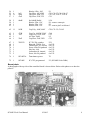
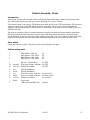
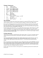
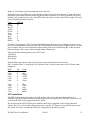
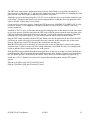
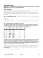
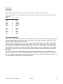
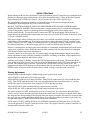
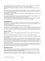
SC100E Scope Clock Kit
Assembly and User Manual
Copyright (C) 2003 Cathode Corner. All rights reserved.
Table of Contents
Introduction ..................................................................................................................................................3
Theory of Operation .....................................................................................................................................4
PC Board Assembly .....................................................................................................................................7
Cabinet Assembly Guide ............................................................................................................................12
Installing in Your Own Cabinet...................................................................................................................17
Initial Checkout...........................................................................................................................................20
Schematic Diagram.....................................................................................................................................23
SC100E Clock User Manual
9/29/05
2
Introduction
The Manual
This user manual is divided into sections. Not all sections are relevant to all users. The Theory of Operation
section is provided for the curious and may be skipped, as it is not necessary to know exactly how the clock
works in order to make it work.
Two sections are provided for cabinets: one for the Plexiglas cabinet, and one for homebuilt cabinets.
The Clock
The SC100 scope clock is an electronic clock that displays the time on a small oscilloscope tube using
artfully drawn numbers. While most digital clocks use a seven-segment display optimized for low cost and
ease of manufacture, the SC100 is optimized for aesthetic appeal.
The clock may be purchased with a sturdy Plexiglas cabinet to protect the fragile CRT and keep the user
isolated from the high voltage used to operate the tube. If the clock was not purchased with a cabinet, the
clock PC board and CRT should be installed in a suitable cabinet of the user's choosing.
Contacting Cathode Corner
If you are having trouble assembling your clock, getting it to work, or you just want to talk with us about
clocks, you may contact Cathode Corner in any of the following ways.
Visit Cathode Corner on the Web at www.cathodecorner.com
Phone: 520-795-7228
Email: [email protected]
Mailing address:
Cathode Corner
2602 E Helen
Tucson AZ 85716
USA
SC100E Clock User Manual
9/29/05
3
Theory of Operation
Power Supply
The power supply is of the offline switching type. AC power is first filtered and rectified, then switched
through a high-frequency transformer to produce the necessary operating voltages.
The most common types of switching power supplies are flyback and forward converters. A forward
converter uses the power driven when the primary switch is conducting, and multiplies that voltage by the
turns ratio. A flyback converter stores energy in the transformer while the switch is on, then transfers that
energy to the secondaries when the switch turns off.
This supply is both of these types in one - its outputs are all fed through voltage doublers, so that both
halves of the cycle are used. This is done to allow the voltage multiplier for the high voltage negative supply
to be regulated as well as the lower-voltage supplies.
The reason is that a forward converter develops a secondary voltage proportional to the turns ratio, whereas
a flyback converter develops a secondary voltage proportional to the duty cycle. These two functions are
different with regard to line voltage, so a regulator for one will develop a lot of 120 Hertz ripple when used
the other way.
AC power flows through a filter, whose job is to remove the switching noise from the power cord. Next is a
rectifier and a filter capacitor to provide 150VDC power to the switching circuit.
The switching IC is a Topswitch made by Power Integrations (www.powerint.com). It interrupts the current
flowing through the primary winding of T1 at a rate of 100 Kilohertz, and controls the duty cycle of this
interruption to provide regulated voltage outputs.
Moving on to the regulator, the deflection voltage is the one actually regulated. The other voltages follow
this voltage in proportion to their turns ratios. The regulator samples the deflection voltage through both a
resistive divider for absolute regulation, and through a series RC network for improved transient response.
The sampling device is an LM431 shunt regulator, which strives to maintain 2.5V from its reference pin to
its anode pin. It regulates the current through the optoisolator to achieve this. The Topswitch senses the
current in the phototransistor of the optoisolator and adjusts the duty cycle of the switch to maintain a
constant current at that point.
The low-voltage supply is pretty straightforward. Since both phases of the switching cycle are used, one
winding can generate both positive and negative DC outputs.
The filament supply is straight AC, since that heats up a wire as well as DC does. An AC-coupled
connection to the filament supply feeds a doubler which powers the optoisolator used for the modulation
signal. This optoisolator is a special logic-level photodiode unit with sub-microsecond switching time.
The Z modulation supply provides enough voltage to switch the grid on and off (~60VDC) and enough
current to do so quickly. A simple transistor switch controls the grid.
CRT Beam circuits
The CRT requires the correct DC voltages at all of its electrodes in order to form a bright yet small spot on
the screen. The cathode may be considered as the starting point of this system.
The grid requires a negative voltage relative to the cathode. This voltage is adjusted by the Intensity control,
and for night-dimming purposes may be controlled by an optional CdS photocell installed in R65.
Blanking is active for that part of the circle that is to be blanked when drawing an arc, and whenever the
beam is being moved from one location to another. Blanking is accomplished by switching the grid to a
much more negative voltage by the Z modulation circuit to cut off the beam.
SC100E Clock User Manual
9/29/05
4
The focus anode requires about +500 volts with respect to the cathode. This voltage is adjustable over a
wide range to accommodate different CRTs with different focus voltage requirements.
The second anode requires about +1500V with respect to the cathode for most 2" and 3" CRTs. This
voltage is adjusted by the Astigmatism control. This control changes the second anode voltage with respect
to the voltage on the deflection plates, since the deflection plates have the secondary effect of acting as
focusing lenses, first in one axis then the other axis. The magnitude of this effect depends on the voltage on
the second anode relative to the average DC voltage on the deflection plates.
Deflection Amps
The deflection amps are push-pull Class A amplifiers, which strive to keep the voltage at the transistor's
emitter at 0.6V below its base by changing the current through the transistor. This in turn changes the
voltage at the collector, according to Ohm's Law. It's not a real fast circuit, but it works for clock use. The
load resistor value is a compromise between speed and heat dissipation.
Numeric display
The digits are formed from circles, lines and arcs. The basic method of drawing a circle on a CRT is called
a Lissajous pattern. This is something that every student of electronics learns about early in school, then
promptly forgets. The only other known use of this numeric display technique is in the HP 1600 logic
analyzer.
A Lissajous pattern is displayed by applying sine waves of different phases to the X and Y deflection plates
of a CRT. A sine wave on the Y plates and a cosine wave on the X plates give a circle. If the phase
difference is zero, then the circle collapses to a slanted line. If Y=0, the line is horizontal, etc.
Each digit is made up of one, two or three segments. Each segment has a center, a size code, and a dwell
time. The center places the segment within the digit's cell space. The size code indicates the X and Y radii of
the circle/ellipse, as well as if it will be a line (x=cos, y=cos) or a circle (x-cos, y=sin). The dwell time is
longer for larger circles to make the intensity appear consistent.
A further piece of information is the arc code. This tells the circuitry which octants of the circle to blank out
to make an arc, such as in the number 2.
A set of three 74HC574 registers holds this information while the segment is being drawn.
The sin and cos waves are made from two taps 90 degrees apart on a shift register fed from a divided-down
version of the CPU clock that runs at 15.36 KHz. A pair of low-pass and bandpass filters produce clean
sin and cos waves from these taps.
The circle size code is fed into a set of CD4066 switches that pass selected amounts of the sin and cos
waves into the X and Y current summing amps. The X and Y position values are converted to currents by
binary-weighted resistors into the summing amps, a crude but effective digital-to-analog converter or DAC.
The X and Y summing amps convert the resulting currents into X and Y deflection voltages, which are
scaled and inverted for use by the push-pull deflection amps.
The screensaver is made with five resistors, which are used to add a small X,Y displacement to the entire
image. This displacement is changed slightly once an hour, and goes through a prime number of steps (31)
before repeating so as to cycle through the hours in an evenly distributed sequence so that no hour digit is
favored in any position on the screen.
Computer program
The software running on the computer is a bit tricky. It has to keep track of the time, send new display
segments to the display circuits on a regular basis, keep track of which buttons are pushed, and keep in
sync with the power line frequency. It manages to do all this somehow.
SC100E Clock User Manual
9/29/05
5
Optional 1PPS Input
An optional 1PPS input allows the clock to take its timekeeping reference from an external atomic clock,
maser or other accurate reference source. The required input signal is TTL level and the clock advances on
the falling edge of the pulse. The signal is connected directly to the CPU’s interrupt request (IRQ) input.
The software detects an interrupt on this pin to enter the 1PPS timekeeping mode. Until and unless such an
interrupt occurs, the clock will use the crystal oscillator divided by the CPU’s timer as the time source.
When the IRQ interrupt happens, the software changes to a mode in which it advances the seconds counter
on each receipt of an interrupt. The clock will not keep time if the 1PPS signal is connected then removed.
SC100E Clock User Manual
9/29/05
6
PC Board Assembly
Tools needed
Soldering Iron, fine tip, 700 degrees F, adjustable temperature preferred
Solder, 63/37 (60/40 is OK), .031" diameter or smaller, rosin or no-clean flux
Small diagonal cutters
Small long-nose pliers
#1 Phillips screwdriver
Getting Started
Dump the parts from the bag into a large tray to make them easy to sort. Then sort out the parts by type for
easy identification as they are needed. If any parts are missing, contact Cathode corner (see page 3) for
assistance.
Parts List
The parts supplied in the kit are listed below in order of installation. 'Step' refers to the assembly sequence.
'Marking' refers to any part number printed on the part itself. The assembly instructions begin after the
parts list.
Resistor color code
0
1
2
3
4
Bk
Bn
R
Or
Ye
5% Gd
Black
Brown
Red
Orange
Yellow
5
6
7
8
9
Gn
Bu
Vi
Gy
Wh
Gold
x.y ohm
Green
Blue
Violet
Grey
White
Gold
The resistors with 5 bands are 1% precision resistors - the third digit is part of the value, the fourth is the
multiplier, and the fifth is one for 1%. There's a gap between the fourth and fifth color bands. The 5%
resistors follow the standard color code – first two digits of value, then the multiplier, then gold for 5%.
PC Board parts
Step Qty
Marking
1
1
SC100E
Description
PCB, blank, SC100E
designators
2
3
4
5
1
2
6
13
ReYeWhOrBn Res, 249K, 1%, 1/4W
YeViYeGd
Res, 470K, 5%, 1/4W
BnBkGnGd Res, 1.0M, 5%, 1/4W
BnBkBkRBn Res, 10.0K, 1%, 1/4W
R10
R9, R21
R8, R20, R66-69
R1-2, R13, R19, R22, R28, R36-41, R57
6
7
8
6
8
5
RBkBkRBn Res, 20.0K, 1%, 1/4W
YeBkRRBn Res, 40.2K, 1%, 1/4W
GyBkBuRBn Res, 80.6K, 1%, 1/4W
R7, R18, R26-27, R33, R71
R6, R17, R25, R30, R35, R46-47, R64
R5, R16, R24, R29, R34
9
10
11
2
2
2
BnBuROrBn Res, 162K, 1%, 1/4W
OrRYeOrBn Res, 324K, 1%, 1/4W
BnRBnOrBn Res, 121K, 1%, 1/4W
R4, R15
R3, R14
R56, R58
SC100E Clock User Manual
9/29/05
7
12
13
14
15
1
4
2
3
RRRGd
RRYeGd
OrOrBnGd
YeViGnBnBn
Res, 2.2K, 5%, 1/4W
Res, 220K, 5%, 1/4W
Res, 330, 5%, 1/4W
Res, 4.75K, 1%, 1/4W
R59
R52-55
R23, R60
R31-32, R72
16
17
18
19
4
1
1
8
BuGyRGd
BnBkRGd
BuGyGdGd
1N4148
Res, 6.8K, 5%, 1/4W
Res, 1.0K, 5%, 1/4W
Res, 6.8, 5%, 1/4W
Diode, switching
R48-51
R73
R74
D5-8, D23-26
20
21
22
1
1
2
BnBkOrGd
P6KE100
UF1002
Res, 10K, 5%, 1/2W
R70
Diode, TVS, 100V bipolar D28
Diode, ultra fast, 200V
D21-22
23
17
UF1006
Diode, ultra fast, 600V
D1-4, D9-20, D27
24
25
26
27
28
29
30
31
32
33
1
1
1
3
1
2
3
1
1
1
74HC151
74HC4040
74HC574
CD4015
CD4066
TL072
H11A817A
6N137
DB105
Socket, DIP, 20pin
IC, DIP, mux
IC, DIP, counter
IC, DIP, register
IC, DIP, register
IC, DIP, switch
IC, DIP, op-amp
IC, optocoupler
IC, optocoupler
Bridge, DIP, 600V, 1A
for U3
U7
U10
U4-6
U11
U8, U12
U13-15
U18
U19
D29
34
35
36
37
38
39
1
1
1
1
6
8
3.93
white
15J or 150
22J or 220
102J
104M
Xtal, 3.93216MHz
Cap, Var, 3-10pF
Cap, Cer, 15pF, 50V
Cap, Cer, 22pF, 50V
Cap, Cer, .001uF, 50V
Cap, Cer, 0.1uF, 50V
Y1 (3.2768MHz for 50Hz)
C3
C2
C1
C10-13, C15-16
C6-8, C18-19, C29, C49-50
40
41
2
1
123J
F1A
Cap, PPS,. 012uF, 50V
Fuse, 1A, 250V
C14, C17 (.018uF for 50Hz)
F1
42
43
2
2
203
104
Pot, 20K, .2x.2"
Pot, 100K, .2x.2"
R42-43
R44-45
44
45
46
2
2
1
103
105
504
Pot, 10K, .1x.2"RA
Pot, 1M, .1x.2"RA
Pot, 500K, .1x.2"RA
R11-12
R61-62
R63
47 1
47a 1
black
black
Header, 2 pin
Jumper shunt, 2 pin
E1
48
49
50
51
52
3
1
1
1
5
78L05
78L09
79L05
LM431
ZTX458
IC, TO92, regulator
IC, TO92, regulator
IC, TO92, regulator
IC, TO92, regulator
Transistor, NPN, HV
U1-2, U20
U9
U16
U17
Q1-5
53
2
T1105
Coil, 8.2mH,Adj.
L1-2
SC100E Clock User Manual
9/29/05
8
54
55
56
57
1
6
13
1
Header, 8 Pin, .100"
Cap, Elect, 1uF, 450V
Cap, Elect, 10uF, 25V
Cap, Elect, 47uF, 25V
P1
C30, C36-37, C40, C46-47
C4-5, C9, C20-27, C38-39
C51
58
59
60
61
2
1
1
1
68uH
Ind, 68uH, Radial
Header, 3Pin, .156"
Header, 5Pin, .156"
Header, 6Pin, .156"
L3-4
P4 - remove center pin
P2
P3 - remove pin 5 to fit board
62
11
103K
Cap, Poly, .01uF, 400V
C28, C31-35, C41-45
63
64
65
66
1
1
1
1
472K
.1uF
Cap, Cer, .0047uF, 250V
Cap, Poly, 0.1UF, 250V
AC filter, 26uH
Cap, Elect, 22uF, 250V
C48
C53
L5
C52
67
68
69
70
71
72
73
1
1
1
1
1
1
2
TOP223
IC, TO-220, switcher
Heatsink, TO220, 1"sq
Thermal pad, TO-220 size
Screw,4-40x5/16,panhead
Nut, hex, 4-40
lockwasher, #4, internal
Screw, #4x1/4, panhead
U21
for U21
for U21
for U21
for U21
for U21
for U21
74
1
SC100T1A
Transformer, power
T1
75
1
SC100E
IC, CPU, programmed
U3 (SC100E-50 for 50Hz)
1uF
10uF
47uF
22uF
Board photo
A photograph of the top side of the assembled board is shown below. Refer to this photo to see how the
parts fit.
SC100E Clock User Manual
9/29/05
9
Step by step guide
The parts list has blank lines between groups of parts. These blank lines indicate when is a good time to
solder all the parts that have been stuffed into the board.
2-18) Install and solder the resistors and 1N4148 diodes first in the order listed. Bend the legs over at a 30degree angle of each resistor as it is installed, to keep it from falling out. Solder and trim the leads at each
blank line in the parts list.
19-23) Install and solder the 1/2 watt resistor and the big diodes next. Observe the polarity lines on the
board. D28, the P6KE100, does not have a polarity mark. It may be installed in either direction.
24-33) Install and solder the DIP ICs next. DO NOT install U3 - install the socket instead. Bend over a
couple corner pins on each IC as it is installed. They may all be installed before any are soldered. Doublecheck the pin 1 markings against the assembly diagram BEFORE soldering.
34-39) Install and solder the crystal Y1, C3, the variable capacitor, and the small ceramic capacitors next.
The 50 Hz version of the clock includes a 3.2768MHz crystal.
40-41) Install and solder the fuse F1 and the PPS capacitors. The 50 Hz version of the clock
includes.018uF PPS capacitors.
42-43) Install and solder the round trim pots next. The single leg on these pots may be squeezed towards
the other two legs a bit BEFORE stuffing to give these pots better holding ability in the PC board holes.
44-46) Install and solder the square trim pots next. Spread the legs on each of these pots after installing. Be
sure to fully seat each pot as it is soldered, to ensure that it fits tightly against the board. Check also for
square alignment to the board to keep a neat appearance.
47) Install and solder the header E1. Put the jumper block on it first so that you don’t burn your fingers
holding it in place while soldering.
48-52) Install and solder the TO92 ICs and transistors next. Be sure to orient these parts with the flat side
as shown on the board silkscreen - the ZTX458 parts have their marking in silver paint on the ROUND
side. Check the parts’ alignment after soldering one pin of each before finishing the soldering work.
53-57) Install and solder the coils, small header and the electrolytic capacitors next. Observe polarity! Note
that the Japanese manufacturers mark the negative lead of the electrolytic capacitors, but the PC board
marks the positive hole with a + sign. The positive leads of the capacitors are longer. So put the long leads
into the plus holes.
58-61) Install and solder P2, P3 and P4. Pull out the pins with missing holes on P3 and P4. This may be
done with cutters used as a lever.
62) Install and solder the big polyester capacitors next. Take care to align them visually if you are putting
the board in a clear cabinet.
63-66) Install and solder the large capacitors and the AC filter next.
67-73) Hold the beige thermal pad onto the heatsink with its hole matching the top hole (the notch is at the
bottom). Mount U21 on the heat sink with the 4-40 x 5/16" screw, lockwasher and nut in the top hole.
Tighten the screw snug bot not real tight. Mount the heat sink/U21 assembly to the board using the two
#4x1/4" sheet metal screws. Solder the pins.
74) Install T1 next. The wire leads coming out the top of the transformer do NOT want to be trimmed to
length, as they are delicate and difficult to strip. Twist the wires in each pair together before soldering.
Connect the two heavy-gauge T1 wires to the PC pads marked "T1FAT", and the light-gauge wires to the
pads labeled "T1THIN". It doesn't matter which color wire goes to which of the two holes. If you
accidentally break a wire end and need to strip it, carefully strip the outer sleeve using a sharp stripping tool,
then melt the enamel insulation with a soldering iron with plenty of solder on the tip.
SC100E Clock User Manual
9/29/05
10
Dress the leads to pass from the transformer around C28, then above the row of diodes. The FAT wires
pass between C36 and C37. See the board photo for details.
75) Insert the CPU chip into the socket at U3. Bend the leads in slightly to make insertion easier. Align the
notch end of the socket and of the CPU chip.
PC board assembly is complete.
SC100E Clock User Manual
9/29/05
11
Cabinet Assembly Guide
Introduction
This section describes the assembly of the clock into the optional Plexiglas cabinet. If you did not order
this cabinet, then skip ahead to the next section, Installing in Your Own Cabinet.
The cabinet is made of two pieces. The bottom piece holds the PC board, CRT and switches. The top part is
simply a cover to protect the CRT and the user from each other. The two pieces are held together for
shipping with four screws. Remove these screws to assemble the clock, then use them to hold on the cover
when you are done.
The wires are provided with pre-crimped terminals to simplify assembly and assure durable connections.
Do NOT insert the terminals into the connector shells until instructed. If a terminal is inserted into the
wrong shell hole, it may be removed by gently pushing down with a 1/8" slot screwdriver blade on the little
tang visible through the slot in the shell while simultaneously pulling the wire gently out of the shell.
Parts check
Check that all parts are there. The parts list shows the marking on the parts.
Cabinet wiring parts
1
1
1
1
Shell, Molex, 8 Pin, red
Shell, Molex, 5 Pin, white
Shell, Molex, 6 Pin, white
Shell, Molex, 3 Pin, white
P1
P2
P3
P4
1
10
8"
Socket, 12 pin duodecal
for CRT
assorted Wire, high-voltage, with pins for CRT
3/16" dia Tubing, heat-shrink
for CRT
1
1
2
2
2"
red
black
red
black
1/4" dia
Switch, pushbutton
Switch, pushbutton
Wire, low-voltage, with pins
Wire, low-voltage, with pins
Tubing, heat-shrink
for red switch
for black switch
for switches
1
1
black
Power cord
1PPS cable with BNC jack
optional
SC100E Clock User Manual
9/29/05
12
Plexiglas Cabinet parts
1
clear
Cabinet top half
1
clear
Cabinet bottom half
2
6-32x3/8 Screw, Phillips pan head
1
6-32x3/4 Screw, Phillips pan head
2
6-32x1
Screw, Phillips pan head
4
6-32x1-1/4Screw, Phillips pan head
6
6-32x1/2 Screw, Phillips flat head
7
6-32
Hex nut
7
#6
Lockwasher
6
#6x1/4
Spacer, nylon
2
6-32x1-1/4Spacer, aluminum
1
Clamp, round, 1.5" diameter for CRT
4
black
Feet, rubber
1
Felt strip, 3/16"x12"
1
3RP1-A CRT, 3" flat face
V1
Felt Installation
The felt strip must be placed into the large front cabinet hole to make the CRT fit snugly. This is the first
cabinet assembly step since it is most easily done before anything is attached to the cabinet bottom.
Peel one inch of backing paper from one end of the felt strip. Stick the end of the felt to the inside of the
hole at the center of the bottom side of the hole (the side closest to the thick bottom plate of the cabinet).
Try to leave about 1/32" (1 mm) of gap between the front edge of the felt strip and the outside edge of the
hole, since this will improve the appearance of the clock.
Peel the backing paper from the felt as you go, guiding the felt strip into place with two fingers as it makes
contact with the plastic. If it starts going on crooked, peel it up and straighten it out as you go. Flip the
cabinet onto each side as you complete each side of the hole, always keeping the working area down so that
you can see what you are doing. When you have completed the circle, cut the felt strip to length so that the
ends nearly meet but do NOT overlap.
PC Board Mounting
The PC board is held in place inside the bottom of the cabinet with six 6-32 screws, lockwashers and nuts,
with the nylon spacers between the PC board and the cabinet bottom, and rubber feet on the four outer
screws.
The task of installing the PC board is best done with the cabinet lying on its side. Insert two 1-1/4" long
screws through two rubber feet. Put these screws into the top front and rear holes (as viewed when
sideways) in the cabinet bottom from the outside. Put one 1" screw into the top center hole from the
outside.
Place one nylon spacer on each of these three screws. Orient the PC board so that the SETTING connector
P1 is near the end of the cabinet with the large CRT hole. While holding the three screws in place with one
hand, use the other hand to place the circuit board over the three screws. Place a lockwasher on the center
screw and thread a nut onto that screw. Run the nut down not quite all the way. Put lockwashers and nuts
on the two corner screws. Run them down most of the way.
Flip the cabinet over onto its other side, and repeat the screw installation procedure for the other three PC
board screws.
SC100E Clock User Manual
9/29/05
13
Power Cord Wiring
Push the small end of the power cord into the 1/4" hole in the cabinet rear panel about one foot, then tie a
knot in the cord 3" from the end to keep it from pulling out of the clock. Push the cord's two Molex pins
into the two end positions of the white 3-pin connector body. The center position is not used.
Pull the power cord out till it stops at the knot. Plug the power cord Molex plug into P4 on the PC board.
Switch Wiring
Cut the two pieces of small-diameter red wire to 3" length from the crimped-on terminal. Strip 1/4" of
insulation off the free end of each wire. Solder one red wire to the 'A' terminal of the red pushbutton switch.
Solder the other red wire to the 'C' terminal of the red switch. Twist the two wires together.
Cut the two pieces of small-diameter black wire to 5" length from the crimped-on terminal. Strip 1/4" of
insulation off the free end of each wire. Solder one black wire to the 'A' terminal of the black pushbutton
switch. Solder the other black wire to the 'C' terminal of the black switch. Twist the two wires together.
Cut two 1/2" long pieces of 1/4" diameter heat shrink tubing. Slide one piece over the terminals of the red
switch and shrink it. Slide the other piece over the terminals of the black switch and shrink it.
Install the red switch in the left hole in the front panel. Install the black switch in the right hole.
If the optional 1PPS input was ordered, there will be a one-foot long coaxial cable in the kit with a female
BNC panel-mount connector at one end and Molex terminals on the other end. Mount the connector into
the 1/2” hole on the rear panel of the cabinet. Route the cable around and under the left side of the PC
board to P1.
Plug the switch wire terminals into the red 8-pin Molex shell according to the table below. Pin 8 of P1 is
closest to the corner of the PC board, and is marked with an 8 on the pin side of the plug. A photo of the
plug is shown below.
Pins
7&8
3&4
1
2
Wires
Red
Black
Ground for Optional 1PPS input
Signal for Optional 1PPS input
Plug the switch plug into P1 on the PC board.
CRT wiring
The kit is supplied with10 different colored pieces of high voltage wire, each with a Molex pin crimped to
one end. These wires will be cut to length, then the free end of each wire will be soldered to a CRT socket
pin and insulated with heat shrink tubing. Finally, the Molex pins will be inserted into their shells.
Cut the Brown, Red, Orange, Yellow and Green wires 5.5" long.
Cut the Blue, Violet, Grey, White and Black wires 7.5" long.
SC100E Clock User Manual
9/29/05
14
Strip 1/4" of insulation off the unterminated end of each wire.
Solder the wires to the CRT pins per the table below. Bend each wire's bare end into a J shape and hook it
through the socket terminal first to ensure a tight mechanical connection. It's best to orient the wires such
that they curl towards the pin 1 side of the CRT socket, since that is 'down' on the CRT assembly. This will
make everything back there look tidy.
Color
CRT Pin
Red
12
Orange
1
Brown
2
Yellow
3
Green
4
Grey
6
Violet
7
Blue
8
White
9
Black
10
Cut ten 1/2" long pieces of 3/16" diameter heat-shrink tubing. Slide one piece of tubing over each wire on
the CRT socket. Shrink the tubing over the CRT socket terminals using a match or lighter for heat, or a heat
gun if you have one. It is best to hold the socket assembly by the wires when doing this, so that you don't
burn your fingers. Don't worry, the heat shrink tubing is flameproof.
Twist together the following three pairs of CRT wires:
Violet-Grey
White-Black
Red-Orange
Plug the Molex pins into the white 5-pin and 6-pin connector shells per the table below.
Pin 1 is marked with a '1' on the plug side of the shell, and is closest to the corner of the PC board when
plugged in.
Shell
Pin
Color
6 pin
1
Brown
6 pin
2
Red
6 pin
3
Orange
6 pin
4
Yellow
6 pin
5
--none-6 pin
6
Green
5 pin
5 pin
5 pin
5 pin
5 pin
1
2
3
4
5
Blue
Violet
Grey
White
Black
CRT Installation
The CRT fits through the front hole and is held in place at the rear by the round clamp with its two
aluminum spacers. It must be rotated correctly to display the time right side up. The CRT socket wires will
exit below the CRT and be plugged into the PC board.
The small end of the CRT is held in place with the round clamp, supported on the two long threaded
spacers. The 3/8" screws hold the clamp to the spacers, and the 1/2" flathead screws hold the spacers into
the cabinet. It is best to assemble the CRT neck components in the following order:
SC100E Clock User Manual
9/29/05
15
The CRT neck clamp must be spread apart from its factory shape. Bend it evenly with your fingers to a
larger diameter, so that there is 1/2" gap where the clamp screw goes. Now bend the two clamping tabs with
pliers towards each other slightly so that they are parallel to each other.
Attach the spacers to the clamp using the 6-32x3/8" screws so that they face away from the cylindrical part
of the clamp. Put them at the outside ends of their elongated holes, so that they are as far apart from each
other as possible. Tighten these screws firmly.
Cover your eyes with safety goggles. Unpack the CRT from its box. HANDLE IT CAREFULLY! It is big
and full of vacuum, so it is dangerous if dropped or broken. Set it back in its box when it is not being
actively worked on.
Install the 6-32x3/4" screw, lockwasher and nut into the clamping holes so that the nut is on the side closest
to one of the spacers. Slide the clamp onto the CRT neck so that the spacers point the same direction as the
CRT pins. Rotate the clamp on the tube base so that pin 7 is next to the clamping screw head. Tighten the
clamping screw snug but not tight, as you will need to rotate the tube to align it with the cabinet.
Plug the CRT socket assembly onto the CRT pins. Some force may be required to do this. Place the CRT
face-down on a table with a piece of newspaper for a pad, rotate the socket so that the key on the socket
lines up with the key on the CRT, then press the socket down onto the pins.
Bend the CRT socket wires so that they all come out of the socket at a right angle, pointed in the general
direction of pin 1, which is on the side of the clamp without the screw. Bend the wires close enough to the
socket so that they do not extend past the end of the spacers.
Slide the CRT/socket assembly through the front panel hole, all the way in so that it is flush with the front
panel. Rotate the CRT to line up the spacers with the rear panel holes, with the clamping screw head facing
up. This should put pin 1 of the CRT at the bottom. This is necessary for the image to be right side up.
Install one 6-32x1/2" flathead screw into each rear panel hole, threading them into the CRT support
spacers.
Plug the 6-pin Molex plug into P3 on the PC board.
Plug the 5-pin Molex plug into P2 on the PC board.
SC100E Clock User Manual
9/29/05
16
Installing in Your Own Cabinet
Selecting a Cabinet
The scope clock requires a cabinet that will support the CRT safely, protect the user from coming in contact
with the high voltages present on the PC board, and allow for adjustment of the controls on the PC board.
The square controls on the edge of the board require adjustment after the clock is set into operating
position, so they should be made accessible, either with holes in the cabinet or by having the cover
removable (but not too easily). A third option is to wire up these controls to front panel potentiometers. Be
aware that the INTEN, ASTIG and FOCUS controls have HIGH VOLTAGE on them, and must be well
insulated from both a metal cabinet and from the user.
One popular type of cabinet to use is an old oscilloscope. The oscilloscope cabinet will already have
suitable controls on the front panel, and it provides a secure mounting for the CRT.
CRT Selection
Here are most of the small cathode ray tubes with which I am familiar. The OK? Column says whether
each tube will work with the Scope Clock. If you need pinout information, feel free to request it from
Cathode Corner. We have tons of useful data sheets and other info available for free
Tube
Base
OK?
Description
902
8CD
No
Octal
906
7AN
No
2.5V@2A filament
913
913
No
Octal, low voltage
1CP1
8
No
Loktal, low voltage
1DP1
9
No
miniature, low voltage
1EP1
11V
Yes
unidekar
2AP1
11B
No
magnal, low voltage
2BP1
12E
Yes
duodecal
3AP1
7AN
No
2.5V@2A filament
3BP1
14A
Yes
diheptal
3DP1
14C
No
electrode in center of screen
3EP1
11A
Yes
magnal
3FP7
14B
Yes
diheptal (needs HV multiplier for A3)
3GP1
11N
Yes
magnal
3JPx
14J
Yes
diheptal (needs HV multiplier for A3)
3KP1
11M odd Yes, but Sell it to a Pilot TV owner for big $$$
3MP1
12F odd Yes
Non-standard duodecal pinout
3RP1
12E
Yes
duodecal
3SP1
12E
Yes
duodecal
3WP1
12E
Yes
duodecal but Left & Right swapped
3ACPx
14J
Yes
diheptal (needs HV multiplier for A3)
3ASP1
8
Yes
RCA small octal (plus button for A2)
3E50
8
Yes
RCA small octal (plus button for A2)
7JP1
14A
Yes
diheptal
The octal base tubes 902 and 913 have two deflection plates connected to the second anode, so they require
two less wires than the balanced-deflection types. This renders the astigmatism control into a diagonal
position control. These tubes have no control over astigmatism, so they tend to have poor spot shape
control over the width of the screen.
SC100E Clock User Manual
9/29/05
17
Mounting the PC Board
The PC board is mounted with the six mounting holes provided. It must be mounted on spacers to keep the
bottom of the PC board at least 1/4 inch away from the panel.
Power cord wiring
Since the scope clock is a clock, a power switch is a hindrance rather than a help. It is recommended to
ignore any power switch in an oscilloscope cabinet being considered for use.
The power cord is supplied with Molex pins crimped onto it. Feed the terminal end of the power cord into
the power cord hole in your cabinet, pull 6 inches of cord through the hole, and tie a knot in the cord for
strain relief.
Plug the two terminals into pins 1 and 3 of the female 3-pin Molex plug body. The cord is not polarized, so
don't worry about which pin is which.
CRT wiring
The kit is supplied with10 different colored pieces of high voltage wire, each with a Molex pin crimped to
one end. These wires will be cut to length, then the free end of each wire will be soldered to a CRT socket
pin and insulated with heat shrink tubing. Finally, the Molex pins will be inserted into their shells.
Strip 1/4" of insulation off the unterminated end of each wire.
CRT pinouts vary, but the ones listed above as magnal (large 11-pin with octal-size key), duodecal (large
12-pin with large key) and diheptal (really large 14-pin) are almost all the same. These pinouts are listed
below. Pin 1 of the two CRT connectors is closest to the corner of the PC board.
Signal
Wire
Magnal Duodecal
Diheptal
Con Pin
Name
Color Pin
Pin
Pin
P3
1
Grid
Brown 10
2
3
P3
2
Heater
Red
1
12
14
P3
3
Heater
Orange 11
1
1
P3
4
Cathode Yellow 2
3
2
P3
6
Anode1 Green 4
4
5
P2
1
Anode2 Blue
7
8
9
P2
2
Bottom
Violet 9
7
7
P2
3
Top
Grey
6
6
8
P2
4
Right
White 3
9
11
P2
5
Left
Black 8
10
10
Solder the wires to the CRT pins per the table above. Bend each wire's bare end into a J shape and hook it
through the socket terminal first to ensure a tight mechanical connection. Some sockets, such as the old
Cinch 14-pin diheptal ones, are made of two parts. On these sockets, there is an insulating ring that fits over
the solder terminals that must be removed before attaching the wires to the terminals. The wires pass
through the same-numbered holes in the insulating ring. The insulating ring is then slid down the wires and
reinstalled on the socket after all the wires have been soldered.
Cut ten 1/2" long pieces of 3/16" diameter heat shrink tubing. Slide one piece of tubing over each wire on
the CRT socket. Shrink the tubing over the CRT socket terminals using a match or lighter for heat, or a heat
gun if you have one. It is best to hold the socket assembly by the wires when doing this, so that you don't
burn your fingers.
Twist together the following three pairs of CRT wires:
SC100E Clock User Manual
9/29/05
18
Violet-Grey
White-Black
Red-Orange
Plug the Molex pins into the white 5-pin and 6-pin connector shells per the table below.
Pin 1 is marked with a '1' on the plug side of the shell, and is closest to the corner of the PC board when
plugged in.
Shell
Pin
Color
6 pin
1
Brown
6 pin
2
Red
6 pin
3
Orange
6 pin
4
Yellow
6 pin
5
--none-6 pin
6
Green
5 pin
5 pin
5 pin
5 pin
5 pin
1
2
3
4
5
Blue
Violet
Grey
White
Black
Connecting Controls
If the scope clock PC board is installed in an old oscilloscope cabinet, it may be desired to connect up some
of the front panel controls to control the scope clock board. The obvious candidates are INTEN, ASTIG,
FOCUS, X POS, Y POS, X SIZ and Y SIZ.
This is a reasonable thing to do, with one caveat: there is HIGH VOLTAGE on the INTEN, FOCUS and
ASTIG controls. The INTEN control has about -1300V on it, the FOCUS has about -900V, and ASTIG
has +300V. Consequently, special high-voltage controls must be used. The controls in the oscilloscope
may be up to the task if they are not too old, but it is best to get new controls of the proper values (ASTIG
and FOCUS values are not critical). Insulate the FOCUS and INTEN controls from the user AND from
the chassis.
The SIZ control wires may require shielding, since they are connected to the X-Y signals that move the
beam. It may be best to leave these as internal adjustments. The POS controls should not cause a problem,
but it is a good idea when remotely mounting these controls to connect a 0.1uF capacitor from the center to
one end terminal of each control to reduce induced noise.
SC100E Clock User Manual
9/29/05
19
Initial Checkout
Before turning on the clock for the first time, inspect the bottom of the PC board for stray component leads
that may be shorting together different pins. Also check for unsoldered pins. Clean off the flux if desired,
using commercially available flux remover. (If you used no-clean flux solder, skip this step.)
The potentiometer adjustments should be at or near the center of their travel as shipped from the
manufacturer. Do not adjust the two coils L1 and L2 till later.
DO NOT TOUCH ANY METAL PARTS ON THE POWER SUPPLY HALF OF THE BOARD
WHILE POWER IS APPLIED! There are hazardous voltages present. Wait 5 seconds after unplugging
power for the primary capacitor to discharge before touching parts on the power supply board.
For the initial powerup , it is not necessary to connect the CRT. The power supply can be checked for
proper function by measuring the voltage from pin 4 to pin 8 of one of the TL072 chips. It should be about
23.5 volts, with pin 8 positive.
If the power supply makes a ticking noise, then there is an overload somewhere, probably resulting from a
solder bridge or mis-installed part. If no ticking noise but no voltage, then there is likely a problem in the
primary circuitry. DO NOT connect test instruments to the power supply primary circuitry unless you use
an isolation transformer, as the power supply primary is connected directly to the power line!
If there is a ticking noise, first inspect the board carefully for components installed backwards in the power
supply areas, especially diodes. If this does not reveal the problem, look for solder bridges or component
leads that are touching where they should not be.
You may connect an oscilloscope to the 12V power supply winding at the cathode (striped) end of D8 to
observe the behavior of the switching controller. It should be oscillating at 100 KHz, with a squarish wave
that has three parts: high low and medium voltage.
After the power supply is running, connect the CRT and apply power to the board. The filament should
glow orange after a few seconds, and some sort of image should appear on the CRT screen after about 20
seconds. The standard image is the time 1:00 (00:00 for 24 hour mode) with very small circles. The
rightmost hours digit will be blinking to indicate that the time has not been set. You may need to turn the
INTEN control 45 degrees clockwise from center to obtain an image, especially with a used CRT.
Display Adjustment
Adjust INTEN so that the display is bright enough to see but not overly bright.
Adjust FOCUS to make the lines as sharp as possible.
Adjust ASTIG to make the lines sharp as follows: Turn FOCUS counterclockwise a bit to make the lines
blurry. Turn ASTIG until the defocus is the same in both horizontal and vertical directions; i.e., the line
width is the same in all directions. Now readjust FOCUS till the lines are sharp.
Adjust X POS and Y POS so that the display is approximately centered.
Adjust X SIZ and Y SIZ so that the image fills the center two thirds of the screen.
The circles are now too small, and the phase of the arcs is not yet set. To correct these, adjust the phase
coils L1 and L2, located near the front right corner of the board. Turn L1 clockwise so that the circles grow
into diagonal lines. Keep turning till the diagonal lines just start to get smaller. Now turn L2 clockwise until
the circles become circular rather than slanted ellipses. You will notice either an overlap or a gap in the two
arcs that make up the 2, which will be corrected in the final adjustments.
Set the time to 12:00 by pushing the black Adv pushbutton repeatedly until the hours show 12. This lets
you see the gap in the 2. Adjust L1 until the two arcs of the 2 are aligned vertically. Adjust L2 until the 0 is
straight and not slanted to either side.
SC100E Clock User Manual
9/29/05
20
After the phase adjustment is done, the SIN control needs to be adjusted so that the two arcs of the 2 line
up with each other. This will also bring the two circles of the 8 into proper contact.
Then, adjust the COS control so that the vertices on the 1, 4 and 7 just meet but do not cross over each
other.
Check that the circles are circular rather than elliptical. Readjust L1 and L2 if needed to make the gap in the
2 very small and the shape of the circles correct. Readjust SIN and COS again if needed. The numbers
should now have the correct shapes.
Adjust X SIZ and Y SIZ so that the display is the right size - the digits should be about 1" tall on a 3" CRT,
and correctly proportioned.
The display will probably be tilted with respect to the cabinet. Rotate the CRT so that the numbers form a
horizontal line. Tighten the neck clamp on the CRT to hold it in position.
Install the cabinet cover so that the holes in th side line up with the five controls on the left side. Use the
four 6-32x1/2" flat head screws that originally held the cabinet together for shipping.
Final Adjustments
The Scope Clock is sensitive to rotation, since the CRT beam is deflected to some extent by the Earth's
magnetic field. Consequently, the X POS and Y POS controls will need to be adjusted AFTER the clock is
set up in it operating position.
The INTEN control also may need adjustment to match the ambient lighting.
The jumper E1 is to be installed to provide 24 hour time display or removed for 12 hour time display. The
leading zero of the hours is not displayed in 12 hour mode only. The jumper is scanned only at power-on
time, so the clock’s power cord must be unplugged and plugged in again for the new setting to take effect.
Setting the time
The Set button cycles the time-setting feature through the digits of the time, causing one digit at a time to
blink.
The Adv button advances the blinking digit through 0-9 or whatever is appropriate for that digit.
When no digit is blinking, the Adv button switches between seconds display and no seconds display each
time it is pushed.
To set the time, push the Set button once. The Hours digit will blink. Push the Adv button, and you will see
the Hours digit advance through the sequence 1,2,3...11,12,1 etc. (00-23 for 24 hour mode). If you look
closely, you will also see the entire time display move slightly up and down as the hour changes. This is the
screensaver feature - by moving the display, it will take much longer for a particular spot on the CRT’s
phosphor to be burned in.
When the hours are set correctly, select the tens of minutes for setting by pushing the Set button again. The
tens-of-minutes digit will now flash. Advance it with the Adv button till it is correct. Repeat for all digits.
Note that the seconds may be set only when they are being displayed.
Regulating the time
Unlike most wall clocks, the scope clock gets its operating frequency from a crystal oscillator. This is
because a switching power supply does not provide an isolated, low-voltage source of AC line frequency,
which is how most other electric clocks obtain their timing.
Set the oscillator frequency by adjusting the trimmer capacitor C1. The slot has an arrow in it - when it
points to the flat side of the capacitor, the oscillator is running fast, and pointing the other way is slow. In-
SC100E Clock User Manual
9/29/05
21
between positions to either clockwise ort counter-clockwise rotation have the same effect, since the
capacitor is made of two half-circles of metal on rotating and stationary ceramic discs.
The capacitor is shipped with the arrow pointing to the round end, which is the slow setting. Rotate the
capacitor clockwise to set the clock faster, then it’s easy to remember that clockwise is faster and
counterclockwise is slower.
A frequency counter may be used to measure the frequency, which will speed p the regulating procedure.
Connect the probe to U10 pin 9, connect the ground lead to U10 pin 8, and adjust for 1.966 080 MHz
(1.638 400 MHz for 50 Hz).
Since crystal oscillators drift with age, the clock regulation may need to be reset periodically. Adjust the
trimmer capacitor C1as needed.
SC100E Clock User Manual
9/29/05
22
Schematic Diagram
SC100E Clock User Manual
9/29/05
23