1
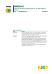
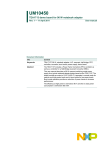
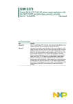
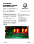
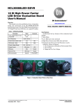
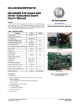
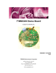
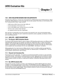
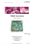
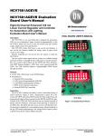
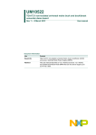
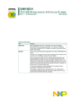
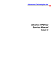
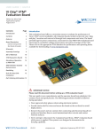
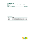
UM10575 SSL4120T 90 W LED driver demo board Rev. 1 — 20 September 2012 User manual Document information Info Content Keywords SSL4120T, SSL4120DB1091, 90 W, LED driver, SSL, LLC, resonant, half-bridge, PFC, controller, converter, demo board, burst mode, user manual Abstract The SSL4120T 90 W LED driver demo board provides a single channel LED driver with an adjustable current controlled output. The maximum output current is 1.5 A. The minimum current is 50 mA which is reached using LLC bust mode. The forward voltage drop of LED string that is driven is between 35 V to 60 V. The SSL4120T includes both a PFC controller and a half-bridge resonant converter controller. The total efficiency at high power is up to 93 %. This user manual describes the SSL4120T 90 W LED driver demo board. Refer to the SSL4120T data sheet for details on the SSL4120T IC. In addition, refer to application note AN11227 for general application information. UM10575 NXP Semiconductors SSL4120T 90 W LED driver demo board Revision history Rev Date Description v.1 20120920 first issue Contact information For more information, please visit: http://www.nxp.com For sales office addresses, please send an email to: [email protected] UM10575 User manual All information provided in this document is subject to legal disclaimers. Rev. 1 — 20 September 2012 © NXP B.V. 2012. All rights reserved. 2 of 33 UM10575 NXP Semiconductors SSL4120T 90 W LED driver demo board 1. Introduction WARNING Lethal voltage and fire ignition hazard The non-insulated high voltages that are present when operating this product, constitute a risk of electric shock, personal injury, death and/or ignition of fire. This product is intended for evaluation purposes only. It shall be operated in a designated test area by personnel qualified according to local requirements and labor laws to work with non-insulated mains voltages and high-voltage circuits. This product shall never be operated unattended. The SSL4120T 90 W demo board (SSL4120DB1091) is a dimmable LED driver example which provides LLC stage burst mode to reach low LED currents. This user manual describes the specification and use of the SSL4120T 90 W LED driver demo board. a. Top view. b. Bottom view. Fig 1. UM10575 User manual Photographs of the SSL4120T demo board All information provided in this document is subject to legal disclaimers. Rev. 1 — 20 September 2012 © NXP B.V. 2012. All rights reserved. 3 of 33 UM10575 NXP Semiconductors SSL4120T 90 W LED driver demo board 2. Safety warning Connect the board to the mains voltage. Avoid touching the board while it is connected to the mains voltage. An isolated housing is obligatory when used in uncontrolled, non-laboratory environments. Galvanic isolation of the mains phase using a variable transformer is always recommended. 019aab174 019aab173 a. Isolated Fig 2. b. Not isolated Variable transformer isolation symbols 3. Specifications Table 1. UM10575 User manual Electrical specification Description Value Condition Line voltage 90 V (AC) to 300 V (AC) - Line frequency 50 Hz or 60 Hz - PO 90 W VO = 60 V; IO = 1.5 A Efficiency 93 % VO = 60 V; IO = 1.5 A; Vmains = 230 V 91 % VO = 60 V; IO = 1.5 A; Vmains = 120 V IO(nom) 1.5 A - VO(min) 35 V - VO(max) 60 V - PF > 0.95 - THD < 15 % - DIM interface 1 V to 10 V - IO(min) 50 mA - IO(max) 1.5 A - Mains harmonics complies with IEC 61000-3-2, Class-C - All information provided in this document is subject to legal disclaimers. Rev. 1 — 20 September 2012 © NXP B.V. 2012. All rights reserved. 4 of 33 UM10575 NXP Semiconductors SSL4120T 90 W LED driver demo board 4. Wiring diagram The mains line voltage input is connected to connector J1. The LED output and the DIM input are connected to connector J2. /(' /(' ',0 ',0 - 66/7 :'(02%2$5' - WRSYLHZ 1HXWUDOEOXH &KDVVLVJUHHQ\HOORZ /LYHEURZQ Fig 3. UM10575 User manual Wiring diagram All information provided in this document is subject to legal disclaimers. Rev. 1 — 20 September 2012 © NXP B.V. 2012. All rights reserved. 5 of 33 UM10575 NXP Semiconductors SSL4120T 90 W LED driver demo board 5. Board information 5.1 Description of the SSL4120T integrated controller The SSL4120T integrates controllers for the PFC and an HBC. The board provides the drive function for the: • discrete MOSFET of the up-converter • two discrete power MOSFETs in a resonant half-bridge configuration The internal high-voltage resonant controller provides Zero-Voltage Switching (ZVS) of the LLC resonant converter. The SSL4120T includes a high-voltage level-shift circuit and several protection features such as: • • • • OverCurrent Protection (OCP) Open-Loop Protection (OLP) Capacitive Mode Protection (CMP) general-purpose latched protection input In addition to the resonant controller, the SSL4120T contains a PFC controller. Efficient PFC operation is achieved using: • quasi-resonant operation at high-power levels • quasi-resonant operation with valley skipping at lower power levels Safe operation under all conditions is guaranteed using: • OverCurrent Protection (OCP) • OverVoltage Protection (OVP) • demagnetization sensing Compared to the TEA1713T, the SSL4120T has a higher PFC frequency limit to support IEC 61000-3-2 Class-C requirements for lighting applications. Table 2. Comparison TEA1713T and SSL4120T Symbol Parameter TEA1713T SSL4120T Unit fmax(PFC) PFC maximum frequency 125 380 kHz toff(PFC)min minimum PFC off-time 1.4 1.1 s The proprietary high-voltage BCD power logic process makes efficient direct start-up from the rectified universal mains voltage possible. A second low-voltage Silicon-On-Insulator (SOI) IC is used for accurate, high speed protection functions and control. The combination of PFC and a resonant controller in one IC makes the SSL4120T an interesting component for very efficient and small LED driver applications. UM10575 User manual All information provided in this document is subject to legal disclaimers. Rev. 1 — 20 September 2012 © NXP B.V. 2012. All rights reserved. 6 of 33 UM10575 NXP Semiconductors SSL4120T 90 W LED driver demo board 5.2 SSL4120T LED demo board block diagram The board can operate at a mains input voltage of between 90 V and 300 V (universal mains). The demo board contains two converter circuits: • a BCM PFC • a resonant LLC HBC The SSL4120T controls both converters. The demo board is to illustrate SSL4120T operation in a single channel current controlled LED driver with burst mode operation during dimming. A limitation is that the output voltage must be between 35 V and 60 V. The performance is according to today’s general standards and can be used as a starting point for further development. mains voltage input FUSE EMI FILTER BRIDGE RECTIFIER POWER FACTOR CORRECTOR HALF BRIDGE DRIVER SSL4120T CONTROLLER LLC RESONAN TANK OUTPUT RECTIFIER OUTPUT FILTER OPTO COUPLER CURRENT SENSE DIM INPUT CIRCUIT ERROR AMPLIFIER LEDs 1 V to 10 V aaa-004734 Fig 4. SSL4120T LED demo board block diagram A typical feature of the demo board is burst mode operation which is used to reach the low LED currents during dimming. An external comparator U2A (shown in the Figure 17) triggers the bursts. To reach the low THD values, the PFC on-time is modulated using the SSL4120T COMPPFC pin. The modulation signal is derived from the mains voltage and it is injected by capacitor C8a in Figure 17. UM10575 User manual All information provided in this document is subject to legal disclaimers. Rev. 1 — 20 September 2012 © NXP B.V. 2012. All rights reserved. 7 of 33 UM10575 NXP Semiconductors SSL4120T 90 W LED driver demo board 6. Measurements 6.1 Test facilities • • • • • • • UM10575 User manual Oscilloscope: LeCroy waveRunner 104Xi AC power source: Agilent 6811B Electronic load: BK Precision 8500 Digital power meter: Yokogawa WT210 Multimeter: Fluke 87V EMI analyzer: Rohde & Schwarz 1164.6407.03 EMI two line V network: Rohde & Schwarz ENV216, 3560.6550.02 All information provided in this document is subject to legal disclaimers. Rev. 1 — 20 September 2012 © NXP B.V. 2012. All rights reserved. 8 of 33 UM10575 NXP Semiconductors SSL4120T 90 W LED driver demo board 6.2 Start-up behavior The output current rise time is approximately 25 ms depending on the output load. a. Vmains = 230 V and minimum load. b. Vmains = 120 V and full load. (1) VGATEPFC. (2) VGATELS. (3) VO. (4) IO. Fig 5. UM10575 User manual Start-up behavior All information provided in this document is subject to legal disclaimers. Rev. 1 — 20 September 2012 © NXP B.V. 2012. All rights reserved. 9 of 33 UM10575 NXP Semiconductors SSL4120T 90 W LED driver demo board 6.3 Protection levels on pins SNSCURHBC and SNSOUT during start-up a. Vmains = 230 V and minimum load. b. Vmains = 120 V and full load. (1) VSNSCURHBC. (2) VSNSOUT. (3) VO. (4) VRCPROT. Fig 6. Protection function behavior during start-up During start-up, the RCPROT (protection timer) pin voltage always rises. The SNSCURHBC pin detects the initial high primary current and the SNSOUT pin starts at a low voltage. UM10575 User manual All information provided in this document is subject to legal disclaimers. Rev. 1 — 20 September 2012 © NXP B.V. 2012. All rights reserved. 10 of 33 UM10575 NXP Semiconductors SSL4120T 90 W LED driver demo board After the first switching cycles, the levels become normal for operation and charging of VRCPROT stops. The VRCPROT level decreases to zero again using the external discharge resistor that is part of the RCPROT system. During normal start-up, the initial charging of VRCPROT must not trigger a protection function (4 V level). 6.4 Efficiency Efficiency measurements are made measuring the output voltage on the board and the current through the LED string. The losses in the output connection cable are not taken into account. Table 3. Efficiency results VO = 60 V. Conditions Efficiency (%) Vmains PO(min) 50 % PO(nom) 100 % PO(nom) 120 V; 60 Hz 51.5 90.3 90.9 230 V; 50 Hz 60 90.7 93.1 277 V; 50 Hz 61.5 90.4 93.2 6.5 Power factor Table 4. Power factor results VO = 60 V. Conditions Power factor Vmains PO(min) 50 % PO(nom) 100 % PO(nom) 120 V; 60 Hz 0.3451 0.9643 0.9896 230 V; 50 Hz 0.1989 0.8993 0.9649 277 V; 50 Hz 0.1543 0.8027 0.9177 50 % PO(nom) 100 % PO(nom) 6.6 Total harmonic distortion Table 5. THD results Measured according IEC method; VO = 60 V. UM10575 User manual Conditions ATHD (%) Vmains PO(min) 120 V; 60 Hz 52.95 9.95 5.76 230 V; 50 Hz 45.50 16.31 11.25 277 V; 50 Hz 37.21 24.35 17.72 All information provided in this document is subject to legal disclaimers. Rev. 1 — 20 September 2012 © NXP B.V. 2012. All rights reserved. 11 of 33 UM10575 NXP Semiconductors SSL4120T 90 W LED driver demo board aaa-004895 160 RMS current (mA) (2) 120 80 40 (1) 0 2 5 9 13 17 21 25 29 33 37 order (1) Full load. (2) IEC limit. Fig 7. Mains harmonics; Vmains = 230 V 6.7 Burst mode operation To reach the low output currents, burst mode operation is implemented in the IC. In the demo board, burst mode is active under approximately 65 W output power. (1) VGATELS. (2) VO. (3) VSNSFB. (4) IO. Fig 8. UM10575 User manual Burst mode operation; Vmains = 230 V and IO = 50 mA All information provided in this document is subject to legal disclaimers. Rev. 1 — 20 September 2012 © NXP B.V. 2012. All rights reserved. 12 of 33 UM10575 NXP Semiconductors SSL4120T 90 W LED driver demo board The interruptive character of burst mode can generate unwanted audible noise. Audible noise levels are low because the burst mode supply only operates at low-power levels. The burst frequency can be controlled using the: • hysteresis of comparator circuit U2A (resistor R27); • output capacitor value (C32, C37); • speed of the control loop (C36, R43). Improvements for the LLC transformer can be considered, such as: • Potting of the transformer windings • Adding of air gap filler to damp acoustic resonance (1) C1 = Z1 = VGATELS. (2) C3 = Z3 = VO. (3) C2 = Z2 = VSNSOUT. (4) C4 = Z4 = IO. Fig 9. HBC switch on/switch off using VSNSOUT in burst mode operation The GATEPFC is not switched off using the SNSOUT pin. However, when checking the GATEPFC signal it is sometimes switched off at light loads. The GATEPFC signal is switched off because the SNSBOOST reaches its OverVoltage Protection (OVP) trigger level. UM10575 User manual All information provided in this document is subject to legal disclaimers. Rev. 1 — 20 September 2012 © NXP B.V. 2012. All rights reserved. 13 of 33 UM10575 NXP Semiconductors SSL4120T 90 W LED driver demo board 6.8 Transient response The load step response is shown in Figure 10. Channels M1 and M2 show the load step from IO(nom) to IO(min). Channels C3 and C4 show the load step from IO(min) to IO(nom). (1) VO. (2) VO. (3) IO. (4) IO. Fig 10. Load step during operation; Vmains = 230 V 6.9 Output ripple current and noise Ripple and noise are measured at full output load. The resonant converter input voltage causes a frequency component in the output current ripple. The ripple is related to the mains voltage frequency (50 Hz or 60 Hz). The resonant converter switching frequency causes the other component in the output current ripple. Table 6. Output ripple and noise current results LF = 50 Hz/60 Hz; HF = HBC switching frequency is approximately 75 kHz Conditions UM10575 User manual Ripple (peak-to-peak) Vmains VO (V) LF (mA) HF (mA) LF (mV) LF (mV) 120 V; 60 Hz 60 22.6 5.6 117.6 38.9 230 V; 50 Hz 60 22.1 5.4 111.3 36.3 277 V; 50 Hz 60 20.4 5.4 113.9 41.9 All information provided in this document is subject to legal disclaimers. Rev. 1 — 20 September 2012 © NXP B.V. 2012. All rights reserved. 14 of 33 UM10575 NXP Semiconductors SSL4120T 90 W LED driver demo board (1) C3 = Z3 = low pass filter (VO, 3 db, 800 kHz). (2) C4 = Z4 = low pass filter (IO, 3 db, 800 kHz). Fig 11. Output current ripple; Vmains = 230 V and IO = 1.5 A 6.10 No-load behavior When an LED string or other load is not attached to the current driver, the output voltage VO rises to a maximum value of approximately 65 V. The controller then enters the latched protection shut-down state due to OVP using the SNSOUT pin. UM10575 User manual All information provided in this document is subject to legal disclaimers. Rev. 1 — 20 September 2012 © NXP B.V. 2012. All rights reserved. 15 of 33 UM10575 NXP Semiconductors SSL4120T 90 W LED driver demo board (1) VGATELS. (2) ISNSOUT. (3) VO. (4) VRFMAX. (5) Frequency C1. Fig 12. No-load behavior; SNSOUT overvoltage protection 6.11 Hold-up time The output is set to full-load and the 90 V mains supply voltage is disconnected. The hold-up time is the time that passes before the output current drops significantly. The hold-up time in this case is 7.4 ms. UM10575 User manual All information provided in this document is subject to legal disclaimers. Rev. 1 — 20 September 2012 © NXP B.V. 2012. All rights reserved. 16 of 33 UM10575 NXP Semiconductors SSL4120T 90 W LED driver demo board (1) Vmains. (2) VO. (3) IO. Fig 13. No-load behavior; SNSOUT overvoltage protection 6.12 Short-circuit behavior A short-circuit on the output of the resonant converter causes the primary current to increase. The SNSCURHBC function detects the increase causing the IC to run at the maximum frequency until the protection timer RCPROT reaches the 4 V protection level. The RCPROT function performs a restart timer function and restarts when the voltage drops to 0.5 V. After the short-circuit is removed, the converter starts up and operates as normal. The RCPROT function is the main protection mechanism. Under certain conditions other protections are activated during the output short-circuit test. In the demoboard, the SUPIC voltage is cycles between the UVP level and start level. Remark: An additional capacitor of 220 F was added to SUPIC for the test in Figure 14(a) to prevent SUPIC reaching the UVP level. UM10575 User manual All information provided in this document is subject to legal disclaimers. Rev. 1 — 20 September 2012 © NXP B.V. 2012. All rights reserved. 17 of 33 UM10575 NXP Semiconductors SSL4120T 90 W LED driver demo board (1) VSNSCURHBC. (2) VO. (3) IRCPROT. (4) IO. a. RCPROT cycle. b. SUPIC cycle. (1) VSUPIC. (2) VO. (3) VRCPROT. (4) IO. Fig 14. Protection functions and restart at output short-circuit UM10575 User manual All information provided in this document is subject to legal disclaimers. Rev. 1 — 20 September 2012 © NXP B.V. 2012. All rights reserved. 18 of 33 UM10575 NXP Semiconductors SSL4120T 90 W LED driver demo board 6.13 LLC voltage and current measurements a. IO = 1.5 A. b. IO = 75 mA. (1) VGATELS. (2) VHB. (3) VCFMIN. (4) Ires. Fig 15. Resonant voltage and current waveforms 6.14 ElectroMagnetic Compatibility (EMC) results Measurement conditions: UM10575 User manual All information provided in this document is subject to legal disclaimers. Rev. 1 — 20 September 2012 © NXP B.V. 2012. All rights reserved. 19 of 33 UM10575 NXP Semiconductors SSL4120T 90 W LED driver demo board • • • • • Type: conducted EMC measurement Frequency range: 150 kHz to 30 MHz Output power: full-load condition Supply voltage: 120 V and 230 V Measuring time: 50 ms The EMC limits are exceeded at around 200 kHz, which is caused by the PFC stage. Check Section 7 “Known limitations” for improvement suggestions. a. Line N; Vmains = 230 V (AC) and IO = 1.5 A. b. Line N; Vmains = 120 V (AC) and IO = 1.5 A Fig 16. Conducted emission tests UM10575 User manual All information provided in this document is subject to legal disclaimers. Rev. 1 — 20 September 2012 © NXP B.V. 2012. All rights reserved. 20 of 33 UM10575 NXP Semiconductors SSL4120T 90 W LED driver demo board 7. Known limitations The SSL4120T demo board is not a reference design. It is a demo board to highlight the features of the SSL4120T IC. There are some known issues with this board. 7.1 No CVCC regulation This demo board only has a current controlled output. When a load is not connected, the output rises to 65 V and the board shuts down. Cycling the power restarts the board. When the load impedance is too high, constant voltage and constant current control (CVCC) can be use to limit the output voltage to 58 V. 7.2 IO(min) high tolerance The minimum output current has a high tolerance in this design. It varies between 35 mA and 50 mA. When designing an LED driver, reduce the minimum current tolerance. A slightly negative voltage can be applied to the DIM input to reduce the LED current below IO(min) for testing. 7.3 Limited VO range The output voltage range is from 35 V to 60 V. Larger voltage ranges are possible when special circuits are added to supply the IC and feedback amplifier. 7.4 EMI conducted emission At some frequencies, the EMI test limits are exceeded. The design can be improved with the following items: • • • • UM10575 User manual PFC inductor start of winding: start the winding closest to the core PFC inductor: shield PFC large signal current loop: reduce area EMI input section and the PFC stage: mount a metal shield between them All information provided in this document is subject to legal disclaimers. Rev. 1 — 20 September 2012 © NXP B.V. 2012. All rights reserved. 21 of 33 xxxx xxxxxxxxxxxxxxxxxxxxxxxxxxxxxx x xxxxxxxxxxxxxx xxxxxxxxxx xxx xxxxxx xxxxxxxxxxxxxxxxxxxxxxx xxxxxxxxxxxxxxxxxxxxxx xxxxx xxxxxx xx xxxxxxxxxxxxxxxxxxxxxxxxxxxxx xxxxxxxxxxxxxxxxxxxxxx xxxxxxxxxxx xxxxxxx xxxxxxxxxxxxxxxxxxx xxxxxxxxxxxxxxxx xxxxxxxxxxxxxx xxxxxx xx xxxxxxxxxxxxxxxxxxxxxxxxxxxxxxxx xxxxxxxxxxxxxxxxxxxxxxxx xxxxxxx xxxxxxxxxxxxxxxxxxxxxxxxxxxxxxxxxxxxxxxxxxxxxx xxxxxxxxxxx xxxxx x x 3 Cx 220 nF ~ ~ 4 C3 470 nF - Q5 FCPF7N60 C15 33 μF W3 W2 C25 47 pF 6 11 C30 22 nF GND_PFC R7 10 Ω C8a 1.8 nF R44 150 Ω +5V R51a 1Ω C8 47 nF R30 1 kΩ R46 10 kΩ R16 0Ω R11 12 kΩ R14 2.2 kΩ R48 27 kΩ Q6 BF722 GND_HB R17 4.7 MΩ C5 4.7 μF R32 11 Ω R51b 1Ω D11 30V U6 LM431 C38 10 μF C27 2.2 nF R47 10 kΩ R51c 1Ω R18 4.7 MΩ R10 33 kΩ R51d 1Ω R33 0Ω U1 SSL4120T COMPPFC SNSMAINS C11 680 nF SNSAUXPFC SNSCURPFC R15 39 kΩ SNSOUT SUPIC C10 10 nF GATEPFC PGND C12 10 nF SUPREG GATELS n.c. SUPHV C13 680 nF D8 BAS316 1 1 24 2 23 3 22 4 21 5 20 6 19 7 18 8 17 9 16 10 15 11 14 12 13 SNSBOOST RCPROT R12 3.6 kΩ R42 4.7 kΩ C35 680 nF 2 SSHBC/EN R51f 1Ω R34 0Ω SNSFB U3 SFH615A-2 RFMAX CFMIN 4 C18 1 nF R13 51 kΩ C9 10 nF 3 SNSCURHBC C29 390 nF + 1 1 R37 n.m. SGND 3 U5 LMV710 OUT 2 - D9 BAS316 4 R49 270 kΩ n.c. HB C36 1 nF C20 330 nF SUPHS R23 10 Ω R25 330 kΩ GATEHS D12 3.9 V R54 1 kΩ GND_HB R39 n.m. HS1 heatsink 82 mm x 33 mm PFC_Q1 C34 n.m. HB_Q4 HB_Q5 HS2 heatsink 62 mm x 33 mm D10 U4 n.m. R41 n.m. GND_IC R19 47 Ω GND_HB +11 V U2A LM393DG 8 V+ U2B LM393DG 1 5 D5 18 V OUT R57 3.3 kΩ 4 V- - 6 Q3 BC847 GND_IC Fig 17. Schematic diagram OUT - C21 680 nF R35 2.2 kΩ 3 2 4 V- + 7 + R31 27 kΩ C23 10 nF C22 2.2 nF aaa-004768 UM10575 22 of 33 © NXP B.V. 2012. All rights reserved. R58 8.2 kΩ D13 BAS316 R26 33 kΩ R27 100 kΩ R22 33 kΩ 8 V+ Dx BAS316 SSL4120T 90 W LED driver demo board R20 75 kΩ C16 2.2 μF C17 2.2 μF R52 2.4 kΩ R53 82 kΩ Ux LM431 C33 n.m. R21 18 kΩ R45 15 kΩ C31 2.2 nF/ Y D4 BYG20J C19 330 pF R43 1 kΩ R50 10 kΩ R38 470 Ω R24 10 Ω W1 GND_STAR R51e 1Ω R40 n.m. C28 220 μF 5 V+ R6 3.6 kΩ + Rev. 1 — 20 September 2012 All information provided in this document is subject to legal disclaimers. C6 100 nF C14 4.7 μF J2 LED and DIM C26 1 nF 9 R9 47 kΩ C39 100 nF C37 22 μF C32 22 μF GND_STAR D3 BAS316 R8b 390 kΩ 4 3 2 1 L5 22 uH 10 R29 22 Ω R8a 110 kΩ 3 2 1 12 + + R4 0.1 Ω 3 + D7 BAS316 R5 100 kΩ Rx 15 kΩ T1 LP-2920HA63-00 C4 n.m. R2 2.2 MΩ C7 470 nF D10 BYQ28X-200 R28 22 Ω Q1 FCPF7N60 R3 5.1 kΩ R1 2.2 MΩ FH1 2.5AT J1 mains 2 C24 47 pF 1 2 V- 2 4 3 1 1 Q4 FCPF7N60 D6 BAS316 7 12 C2 470 nF + L2 12 mH D2 BYV25X-600 L4 250 μH 9 BR1 GBU806 NXP Semiconductors L3 220 μH L1 1 mH/1 A 8. Schematic UM10575 User manual D1 BYV25X-600 C1 220 nF UM10575 NXP Semiconductors SSL4120T 90 W LED driver demo board 9. PCB layout a. Top view. b. Bottom view. Fig 18. PCB layout UM10575 User manual All information provided in this document is subject to legal disclaimers. Rev. 1 — 20 September 2012 © NXP B.V. 2012. All rights reserved. 23 of 33 UM10575 NXP Semiconductors SSL4120T 90 W LED driver demo board 10. Bill of materials Table 7. Bill of materials Reference Description and value Part number Manufacturer BR1 diode bridge; 8 A; 800 V; SMA GBU806 Taiwan Semiconductor C1 capacitor; polypropylene; 220 nF; 310 V; 20 %; X2; RDL R46KI322050M2K ARCOTRONICS C2 capacitor; MKP; 470 nF; 450 V; 10 %; RDL B32652A4474J000 EPCOS C3 capacitor; MKP; 470 nF; 450 V; 10 %; RDL B32652A4474J000 EPCOS C4 capacitor; NP0; not mounted; 500 V; 5 %; 1206 12067A221JAT2A AVX C5 capacitor; X7R; 4.7 F; 50 V; 10 %; 1210 C1210C475K5- RAC7800 KEMET C6 capacitor; X7R; 100 nF; 50 V; 10 %; 0805 MCCA000386 Multicomp C7 capacitor; X7R; 470 nF; 25 V; 10 %; 0805 C0805C474K3RAC KEMET C8 capacitor; X7R; 47 nF; 25 V; 10 %; 0805 08053C473KAT2A AVX C8a capacitor; X7R; 1.8 nF; 100 V; 10 %; 0805 C0805C182K1RAC KEMET C9 capacitor; X7R; 10 nF; 50 V; 10 %; 0805 CC0805KRX7R9BB103 Yageo C10 capacitor; X7R; 10 nF; 50 V; 10 %; 0805 CC0805KRX7R9BB103 Yageo C11 capacitor; X7R; 680 nF; 50 V; 10 %; 0805 C0805C684K5RACTU KEMET C12 capacitor; X7R; 10 nF; 500 V; 10 %; 1206 12067C103KAT2A AVX C13 capacitor; X7R; 680 nF; 50 V; 10 %; 0805 C0805C684K5RACTU KEMET C14 capacitor; aluminum; 4.7 F; 100 V; 10 %; RDL RD2A475M05011PC SAMWHA C15 capacitor; aluminum; 33 F; 450 V; 20 %; RDL 450BXC33MEFC16X25 RUBYCON C16 capacitor; Y5V; 2.2 F; 25 V; +80 % to 20 %; 0805 GRM21BF51E225ZA01L Murata C17 capacitor; Y5V; 2.2 F; 25 V; +80 % to 20 %; 0805 GRM21BF51E225ZA01L Murata C18 capacitor; X7R; 1 nF; 50 V; 10 %; 0805 CC0805KRX7R9BB102 Yageo C19 capacitor; C0G/NP0; 330 pF; 50 V; 5 %; 0805 CC0805JRNPO9BN331 Yageo C20 capacitor; X7R; 330 nF; 25 V; 10 %; 0805 C0805C334K3RACTU KEMET C21 capacitor; X7R; 680 nF; 50 V; 10 %; 0805 C0805C684K5RACTU KEMET C22 capacitor; X7R; 2.2 nF; 50 V; 10 %; 0805 CC0805KRX7R9BB222 Yageo C23 capacitor; X7R; 10 nF; 25 V; 10 %; 0805 CC0805KRX7R8BB103 Yageo C24 capacitor; C0G/NP0; 47 pF; 500 V; 5 %; 0805 12067A470JAT2A AVX C25 capacitor; C0G/NP0; 47 pF; 500 V; 5 %; 1206 12067A470JAT2A AVX C26 capacitor; Class 2; disc; 1 nF; 1 kV; 10 % F102K39Y5RN6UJ5R Vishay BC Components C27 capacitor; X7R; 2.2 nF; 50 V; 10 %; 0805 CC0805KRX7R9BB222 Yageo C28 capacitor; aluminum; 220 F; 50 V; 20 %; RDL 50YXF220MEFC10X16 RUBYCON C29 capacitor; polyester film; 390 nF; 50 V; 5 %; RDL ECQV1H394JL Panasonic C30 capacitor; polypropylene; 22 nF; 1.25 kV; 5 %; RDL B32652A7223J000 EPCOS C31 Y-capacitor X1/Y1; disc; 2.2 nF; 250 V; 20 % DE1E3KX222MA5BA01 Murata C32 capacitor; aluminum; 22 F; 100 V; 20 %; RDL EEUFC2A220 Panasonic C33 capacitor; X7R; not mounted; 50 V; 10 %; 0805 CC0805KRX7R9BB222 Yageo C34 capacitor; X7R; not mounted; 25 V; 10 %; 0805 08053C473KAT2A AVX C35 capacitor; X7R; 680 nF; 50 V; 10 %; 0805 C0805C684K5RACTU KEMET C36 capacitor; X7R; 1 nF; 50 V; 10 %; 0805 CC0805KRX7R9BB102 Yageo UM10575 User manual All information provided in this document is subject to legal disclaimers. Rev. 1 — 20 September 2012 © NXP B.V. 2012. All rights reserved. 24 of 33 UM10575 NXP Semiconductors SSL4120T 90 W LED driver demo board Table 7. Bill of materials …continued Reference Description and value Part number Manufacturer C37 capacitor; aluminum; 22 F; 100 V; 20 %; RDL EEUFC2A220 Panasonic C38 capacitor; aluminum; 10 F; 50 V; 20 %; RDL 50ML10MEFC5X7 RUBYCON C39 capacitor; X7R; 100 nF; 100 V; 10 %; 1206 C1206C104K1RACTU KEMET Cx capacitor; polypropylene; 220 nF; 310 V; 20 %; X2; RDL BFC233922224 Vishay BC Components D1 diode; ultra-fast; 600 V; 5 A; 1.3 VF; TH BYV25X-600,127 NXP Semiconductors D2 diode; ultra-fast; 600 V; 5 A; 1.3 VF; TH BYV25X-600,127 NXP Semiconductors D3 diode; ultra-fast; 100 V; 0.215 A; 1.25 VF; SMA BAS316,135 NXP Semiconductors D4 diode; ultra-fast; 600 V; 1.5 A; 1.4 VF; SMA BYG20J-E3/TR Vishay Semiconductor D5 diode; Zener; 18 V; 0.3 W; 5 %; SMA BZX384-C18,115 NXP Semiconductors D6 diode; ultra-fast; 100 V; 0.215 A; 1.25 VF; SMA BAS316,135 NXP Semiconductors D7 diode; ultra-fast; 100 V; 0.215 A; 1.25 VF; SMA BAS316,135 NXP Semiconductors D8 diode; ultra-fast; 100 V; 0.215 A; 1.25 VF; SMA BAS316,135 NXP Semiconductors D9 diode; ultra-fast; 100 V; 0.215 A; 1.25 VF; SMA BAS316,135 NXP Semiconductors D10 diode; ultra-fast; dual; 200 V; 10 A; 1.1 VF; TH BYQ28X-200,127 NXP Semiconductors D11 diode Zener; 30 V; 0.3 W; 5 %; SMA BZX384-C30,115 NXP Semiconductors D12 diode Zener; 3.9 V; 0.3 W; 5 %; SMA BZX384-C3V9,115 NXP Semiconductors D13 diode; ultra-fast; 100 V; 0.215 A; 1.25 VF; SMA BAS316,135 NXP Semiconductors Dx diode; ultra-fast; 100 V; 0.215 A; 1.25 VF; SMA BAS316,135 NXP Semiconductors FH1 fuse; 2.5 AT; 250 V; TH 031302.5HXP Littelfuse HS1 heatsink; 82 mm 33 mm not applicable not applicable HS2 heatsink; 62 mm 33 mm not applicable not applicable J1 mains connector term block; 250 V; 28 A; 5.08 mm; 3P; TH 1711738 Phoenix Contact J2 LED and DIM connector terminal block; 250 V 28 A; 5.08 mm; 4P; TH 1712805 Phoenix Contact L1 inductor common mode; 1 mH; 2 A; 30 %; TH 7446122001 WURTH ELEKTRONIK L2 inductor common mode; 12 mH; 1.2 A; 30 %; TH 7446221012 WURTH ELEKTRONIK L3 inductor; 220 H; 3 A; 10 %; TH 744136 WURTH ELEKTRONIK L4 inductor PFC; 250 H; 5.7 A; 10 %; TH 760806110 WURTH ELEKTRONIK L5 inductor; 22 H; 3 A; 10 %; TH 744131 WURTH ELEKTRONIK Q1 transistor; NMOST; 600 V; 7 A; 0.53 ; TH FCPF7N60 Fairchild Q3 transistor; NPN; 45 V; 0.2 A; SMA BC847.215 NXP Semiconductors Q4 transistor; NMOST; 600 V; 7 A; 0.53 ; TH FCPF7N60 Fairchild Q5 transistor; NMOST; 600 V; 7 A; 0.53 ; TH FCPF7N60 Fairchild Q6 transistor; NPN; 250 V; 0.1 A SMA 771-BF722-T/R NXP Semiconductors R1 resistor; thick film; 2.2 M; 200 V; 1 %; 1206 RC1206 Series Yageo R2 resistor; thick film; 2.2 M; 200 V; 1 %; 1206 RC1206 Series Yageo R3 resistor; thick film; 5.1 k; 150 V; 1 %; 0805 RC0805 Series Yageo R4 resistor; thick film; 0.1 ; 200 V; 1 W; 1 %; 2010 LR2010-R10FW Welwyn Components R5 resistor; thick film; 100 k; 150 V; 1 %; 0805 RC0805 Series Yageo R6 resistor; thick film; 3.6 k; 150 V; 1 %; 0805 RC0805 Series Yageo UM10575 User manual All information provided in this document is subject to legal disclaimers. Rev. 1 — 20 September 2012 © NXP B.V. 2012. All rights reserved. 25 of 33 UM10575 NXP Semiconductors SSL4120T 90 W LED driver demo board Table 7. Bill of materials …continued Reference Description and value Part number Manufacturer R7 resistor; thick film; 10 ; 150 V; 1 %; 0805 RC0805 Series Yageo R8a resistor; thick film; 110 k; 150 V; 1 %; 0805 RC0805 Series Yageo R8b resistor; thick film; 390 k; 150 V; 1 %; 0805 RC0805 Series Yageo R9 resistor; thick film; 47 k; 150 V; 1 %; 0805 RC0805 Series Yageo R10 resistor; thick film; 33 k; 150 V; 1 %; 0805 RC0805 Series Yageo R11 resistor; thick film; 12 k; 150 V; 1 %; 0805 RC0805 Series Yageo R12 resistor; thick film; 3.6 k; 150 V; 1 %; 0805 RC0805 Series Yageo R13 resistor; thick film; 51 k; 150 V; 1 %; 0805 RC0805 Series Yageo R14 resistor; thick film; 2.2 k; 150 V; 1 %; 0805 RC0805 Series Yageo R15 resistor; thick film; 39 k; 150 V; 1 %; 0805 RC0805 Series Yageo R16 resistor; thick film; 0 ; 200 V; 1 %; 1206 RC1206 Series Yageo R17 resistor; thick film; 4.7 M; 200 V; 1 %; 1206 RC1206 Series Yageo R18 resistor; thick film; 4.7 M; 200 V; 1 %; 1206 RC1206 Series Yageo R19 resistor; thick film; 47 ; 150 V; 1 %; 0805 RC0805 Series Yageo R20 resistor; thick film; 75 k; 150 V; 1 %; 0805 RC0805 Series Yageo R21 resistor; thick film; 18 k; 150 V; 1 %; 0805 RC0805 Series Yageo R22 resistor; thick film; 33 k; 150 V; 1 %; 0805 RC0805 Series Yageo R23 resistor; thick film; 10 ; 150 V; 1 %; 0805 RC0805 Series Yageo R24 resistor; thick film; 10 ; 150 V; 1 %; 0805 RC0805 Series Yageo R25 resistor; thick film; 330 k; 150 V; 1 %; 0805 RC0805 Series Yageo R26 resistor; thick film; 33 k; 150 V; 1 %; 0805 RC0805 Series Yageo R27 resistor; thick film; 100 k; 150 V; 1 %; 0805 RC0805 Series Yageo R28 resistor; thick film; 22 ; 150 V; 1 %; 0805 RC0805 Series Yageo R29 resistor; thick film; 22 ; 150 V; 1 %; 0805 RC0805 Series Yageo R30 resistor; thick film; 1 k; 150 V; 1 %; 0805 RC0805 Series Yageo R31 resistor; thick film; 27 k; 150 V; 1 %; 0805 RC0805 Series Yageo R32 resistor; thick film; 11 ; 150 V; 1 %; 0805 RC0805 Series Yageo R33 resistor; thick film; 0 ; 200 V; 1 %; 1206 RC1206 Series Yageo R34 resistor; thick film; 0 ; 200 V; 1 %; 1206 RC1206 Series Yageo R35 resistor; thick film; 2.2 k; 150 V; 1 %; 0805 RC0805 Series Yageo R36 resistor; thick film; not mounted; 150 V; 1 %; 0805 RC0805 Series Yageo R37 resistor; thick film; not mounted; 150 V; 1 %; 0805 RC0805 Series Yageo R38 resistor; thick film; 470 ; 150 V; 1 %; 0805 RC0805 Series Yageo R39 resistor; thick film; not mounted; 150 V; 1 %; 0805 RC0805 Series Yageo R41 resistor; thick film; not mounted; 150 V; 1 %; 0805 RC0805 Series Yageo R42 resistor; thick film; 4.7 k; 150 V; 1 %; 0805 RC0805 Series Yageo R43 resistor; thick film; 1 k; 150 V; 1 %; 0805 RC0805 Series Yageo R44 resistor; thick film; 150 ; 150 V; 1 %; 0805 RC0805 Series Yageo R45 resistor; thick film; 15 k; 150 V; 1 %; 0805 RC0805 Series Yageo R46 resistor; thick film; 10 k; 150 V; 1 %; 0805 RC0805 Series Yageo R47 resistor; thick film; 10 k; 150 V; 1 %; 0805 RC0805 Series Yageo UM10575 User manual All information provided in this document is subject to legal disclaimers. Rev. 1 — 20 September 2012 © NXP B.V. 2012. All rights reserved. 26 of 33 UM10575 NXP Semiconductors SSL4120T 90 W LED driver demo board Table 7. Bill of materials …continued Reference Description and value Part number Manufacturer R48 resistor; thick film; 27 k; 200 V; 1 %; 1206 RC1206 Series Yageo R49 resistor; thick film; 270 k; 150 V; 1 %; 0805 RC0805 Series Yageo R50 resistor; thick film; 10 k; 150 V; 1 %; 0805 RC0805 Series Yageo R51a resistor; thick film; 1 ; 200 V; 1 W; 1 %; 1218 RC1218FK-071RL Yageo R51b resistor; thick film; 1 ; 200 V; 1 W; 1 %; 1218 RC1218FK-071RL Yageo R51c resistor; thick film; 1 ; 200 V; 1 W; 1 %; 1218 RC1218FK-071RL Yageo R51d resistor; thick film; 1 ; 200 V; 1 W; 1 %; 1218 RC1218FK-071RL Yageo R51e resistor; thick film; 1 ; 200 V; 1 W; 1 %; 1218 RC1218FK-071RL Yageo R51f resistor; thick film; 1 ; 200 V; 1 W; 1 %; 1218 RC1218FK-071RL Yageo R52 resistor; thick film; 2.4 k; 150 V; 1 %; 0805 RC0805 Series Yageo R53 resistor; thick film; 82 k; 150 V; 1 %; 0805 RC0805 Series Yageo R54 resistor; thick film; 1 k; 150 V; 1 %; 0805 RC0805 Series Yageo R56 resistor; thick film; not mounted; 150 V; 1 %; 0805 RC0805 Series Yageo R57 resistor; thick film; 3.3 k; 150 V; 1 %; 0805 RC0805 Series Yageo R58 resistor; thick film; 8.2 k; 150 V; 1 %; 0805 RC0805 Series Yageo Rx resistor; metal film; 15 k; 350 V; 1 %; TH MRS25000C1502FCT00 Vishay BC Components T1 transformer LLC; 1.4 mH; Lp 225 H; Ll 10 % LP-2920HA63-00 Yu-Jing U1 SSL4120T; IC combi-controller; LLC and PFC; SMA 9352 983 46518 NXP Semiconductors U2 LM393DG; IC comparator; dual; SMA LM393DG ON Semiconductors U3 SFH615A-2; IC opto-transistor O/P TH SFH615A-2 Vishay Semiconductor U4 IC shunt REG 2.5 V; not mounted; SMA LM431AIM3 National U5 LMV710; IC operational amplifier; 5 V; 5 MHz; SMA LMV710M5 National U6 LM431; IC shunt regulator; 2.5 V; SMA LM431AIM3 National Ux LM431; IC shunt regulator; 2.5 V; SMA LM431AIM3 National W1 GND; PCB layout pattern interconnect - - W2 GND; PCB layout pattern interconnect - - W3 GND; PCB layout pattern interconnect - - UM10575 User manual All information provided in this document is subject to legal disclaimers. Rev. 1 — 20 September 2012 © NXP B.V. 2012. All rights reserved. 27 of 33 UM10575 NXP Semiconductors SSL4120T 90 W LED driver demo board 11. Inductor appearance and dimensions 11.1 Power factor corrector inductor L4 • • • • Core: RM10 (EPCOS or equivalent) Core material: NC-2H Bobbin: RM10; 8-pin version (EPCOS or equivalent) Primary inductance: 250 H, 10 % PRI SEC N1 N2 TOP PIN 12 9 N2 1 7 E1, E2 N1 start teflon tube BOBBIN aaa-004780 Fig 19. Power factor corrector inductor L4 Table 8. Power factor corrector inductor winding specification Winding UM10575 User manual Terminal number Winding specifications Mylar tape Order number Start Finish 1 N1 9 7 USTC 0.1 and * 30 * 1 * 40 Ts 1 Ts 2 N1 12 1 2UEW 0.22 and * 2 * 2.5 Ts 3 Ts All information provided in this document is subject to legal disclaimers. Rev. 1 — 20 September 2012 © NXP B.V. 2012. All rights reserved. 28 of 33 UM10575 NXP Semiconductors SSL4120T 90 W LED driver demo board 11.2 Half-bridge transformer T1 30 max 40 max LP-2920HA63 D/C YJ 22 max 4.0 ± 0.5 1 6 0.8 Ø ± 0.1 12 1 12 7 1 6 5 ± 0.5 mylar tape 1L 7 12 33 ± 1 6 1 aaa-004781 dimensions in mm. All dimensions in mm Fig 20. Half-bridge transformer T1 mechanical specification Table 9. Half-bridge transformer T1 winding specification Winding Terminal number User manual Turns Inductance DCR number Start Finish L1 3 6 0.10 * 25 s * 1c (litz) 50 1.4 mH 340 m L2 2 1 0.20 *1c (TEX-E) 6 20 H 250 m L3 11 12 0.10 *30 s*1c (litz) 16 140 H 95 m L4 9 10 0.10 * 30 s*1c (litz) 16 140 H 95 m LIk[1] 3 6 - - 225 H - [1] UM10575 Wire Llk measured with L2, L3 and L4 short-circuited. All information provided in this document is subject to legal disclaimers. Rev. 1 — 20 September 2012 © NXP B.V. 2012. All rights reserved. 29 of 33 UM10575 NXP Semiconductors SSL4120T 90 W LED driver demo board pin #2 pin #11 pin #1 pin #12 pin #3 pin #9 pin #6 pin #10 N2 - aux N3 - sec _1 N1 - prim N4 - sec_2 aaa-004782 All dimensions in mm Fig 21. Half-bridge transformer T1 electrical specification Table 10. Half-bridge transformer electrical specifications Parameter Value Remark Primary inductance 1.4 mH 10 % Leakage inductance (4 to 1) 225 H 10 % Operating frequency) 60 Hz to 100 Hz - Total power ~ 90 W - Turns ratio N1 : N2 : N3 : N4 50 : 6 : 16 : 16 see Table 9 Ipri (N1) 0.5 A RMS maximum Isec (N3 : N4) 2 A RMS maximum Iaux (N2) 100 mA maximum pin 12(10) N4: Ø0.10 * 30 s * 1c * 16 Ts(LITZ) N3: Ø0.10 * 30 s * 1c * 16 Ts(LITZ) *pin 11(9) 17.5 Ts ref 18 Ts ref N1: Ø0.10 * 25 s * 1c *50 Ts(LITZ) 14.5 Ts ref pin 1 N2: Ø0.20 * 1c * 6 Ts(TEX-E) * pin 2 MYLAR tape 2Ts pin 6 * pin 3 pin 1 to 6 BOBBIN pin 7 to 12 aaa-004783 Fig 22. Half-bridge transformer construction and winding order UM10575 User manual All information provided in this document is subject to legal disclaimers. Rev. 1 — 20 September 2012 © NXP B.V. 2012. All rights reserved. 30 of 33 UM10575 NXP Semiconductors SSL4120T 90 W LED driver demo board 12. References UM10575 User manual [1] SSL4120 — Resonant power supply control IC with PFC data sheet [2] AN11227 — SSL4120 resonant power supply control IC with PFC application note All information provided in this document is subject to legal disclaimers. Rev. 1 — 20 September 2012 © NXP B.V. 2012. All rights reserved. 31 of 33 UM10575 NXP Semiconductors SSL4120T 90 W LED driver demo board 13. Legal information 13.1 Definitions Draft — The document is a draft version only. The content is still under internal review and subject to formal approval, which may result in modifications or additions. NXP Semiconductors does not give any representations or warranties as to the accuracy or completeness of information included herein and shall have no liability for the consequences of use of such information. 13.2 Disclaimers Limited warranty and liability — Information in this document is believed to be accurate and reliable. However, NXP Semiconductors does not give any representations or warranties, expressed or implied, as to the accuracy or completeness of such information and shall have no liability for the consequences of use of such information. NXP Semiconductors takes no responsibility for the content in this document if provided by an information source outside of NXP Semiconductors. In no event shall NXP Semiconductors be liable for any indirect, incidental, punitive, special or consequential damages (including - without limitation - lost profits, lost savings, business interruption, costs related to the removal or replacement of any products or rework charges) whether or not such damages are based on tort (including negligence), warranty, breach of contract or any other legal theory. Notwithstanding any damages that customer might incur for any reason whatsoever, NXP Semiconductors’ aggregate and cumulative liability towards customer for the products described herein shall be limited in accordance with the Terms and conditions of commercial sale of NXP Semiconductors. Right to make changes — NXP Semiconductors reserves the right to make changes to information published in this document, including without limitation specifications and product descriptions, at any time and without notice. This document supersedes and replaces all information supplied prior to the publication hereof. Suitability for use — NXP Semiconductors products are not designed, authorized or warranted to be suitable for use in life support, life-critical or safety-critical systems or equipment, nor in applications where failure or malfunction of an NXP Semiconductors product can reasonably be expected to result in personal injury, death or severe property or environmental damage. NXP Semiconductors and its suppliers accept no liability for inclusion and/or use of NXP Semiconductors products in such equipment or applications and therefore such inclusion and/or use is at the customer’s own risk. Applications — Applications that are described herein for any of these products are for illustrative purposes only. NXP Semiconductors makes no representation or warranty that such applications will be suitable for the specified use without further testing or modification. Customers are responsible for the design and operation of their applications and products using NXP Semiconductors products, and NXP Semiconductors accepts no liability for any assistance with applications or customer product UM10575 User manual design. It is customer’s sole responsibility to determine whether the NXP Semiconductors product is suitable and fit for the customer’s applications and products planned, as well as for the planned application and use of customer’s third party customer(s). Customers should provide appropriate design and operating safeguards to minimize the risks associated with their applications and products. NXP Semiconductors does not accept any liability related to any default, damage, costs or problem which is based on any weakness or default in the customer’s applications or products, or the application or use by customer’s third party customer(s). Customer is responsible for doing all necessary testing for the customer’s applications and products using NXP Semiconductors products in order to avoid a default of the applications and the products or of the application or use by customer’s third party customer(s). NXP does not accept any liability in this respect. Export control — This document as well as the item(s) described herein may be subject to export control regulations. Export might require a prior authorization from competent authorities. Evaluation products — This product is provided on an “as is” and “with all faults” basis for evaluation purposes only. NXP Semiconductors, its affiliates and their suppliers expressly disclaim all warranties, whether express, implied or statutory, including but not limited to the implied warranties of non-infringement, merchantability and fitness for a particular purpose. The entire risk as to the quality, or arising out of the use or performance, of this product remains with customer. In no event shall NXP Semiconductors, its affiliates or their suppliers be liable to customer for any special, indirect, consequential, punitive or incidental damages (including without limitation damages for loss of business, business interruption, loss of use, loss of data or information, and the like) arising out the use of or inability to use the product, whether or not based on tort (including negligence), strict liability, breach of contract, breach of warranty or any other theory, even if advised of the possibility of such damages. Notwithstanding any damages that customer might incur for any reason whatsoever (including without limitation, all damages referenced above and all direct or general damages), the entire liability of NXP Semiconductors, its affiliates and their suppliers and customer’s exclusive remedy for all of the foregoing shall be limited to actual damages incurred by customer based on reasonable reliance up to the greater of the amount actually paid by customer for the product or five dollars (US$5.00). The foregoing limitations, exclusions and disclaimers shall apply to the maximum extent permitted by applicable law, even if any remedy fails of its essential purpose. Translations — A non-English (translated) version of a document is for reference only. The English version shall prevail in case of any discrepancy between the translated and English versions. 13.3 Trademarks Notice: All referenced brands, product names, service names and trademarks are the property of their respective owners. All information provided in this document is subject to legal disclaimers. Rev. 1 — 20 September 2012 © NXP B.V. 2012. All rights reserved. 32 of 33 UM10575 NXP Semiconductors SSL4120T 90 W LED driver demo board 14. Contents 1 2 3 4 5 5.1 5.2 6 6.1 6.2 6.3 6.4 6.5 6.6 6.7 6.8 6.9 6.10 6.11 6.12 6.13 6.14 7 7.1 7.2 7.3 7.4 8 9 10 11 11.1 11.2 12 13 13.1 13.2 13.3 14 Introduction . . . . . . . . . . . . . . . . . . . . . . . . . . . . 3 Safety warning . . . . . . . . . . . . . . . . . . . . . . . . . . 4 Specifications. . . . . . . . . . . . . . . . . . . . . . . . . . . 4 Wiring diagram. . . . . . . . . . . . . . . . . . . . . . . . . . 5 Board information . . . . . . . . . . . . . . . . . . . . . . . 6 Description of the SSL4120T integrated controller . . . . . . . . . . . . . . . . . . . . . . . . . . . . . . 6 SSL4120T LED demo board block diagram . . . 7 Measurements . . . . . . . . . . . . . . . . . . . . . . . . . . 8 Test facilities . . . . . . . . . . . . . . . . . . . . . . . . . . . 8 Start-up behavior . . . . . . . . . . . . . . . . . . . . . . . 9 Protection levels on pins SNSCURHBC and SNSOUT during start-up. . . . . . . . . . . . . . . . . 10 Efficiency . . . . . . . . . . . . . . . . . . . . . . . . . . . . 11 Power factor . . . . . . . . . . . . . . . . . . . . . . . . . . 11 Total harmonic distortion. . . . . . . . . . . . . . . . . 11 Burst mode operation . . . . . . . . . . . . . . . . . . . 12 Transient response . . . . . . . . . . . . . . . . . . . . . 14 Output ripple current and noise . . . . . . . . . . . 14 No-load behavior . . . . . . . . . . . . . . . . . . . . . . 15 Hold-up time . . . . . . . . . . . . . . . . . . . . . . . . . . 16 Short-circuit behavior . . . . . . . . . . . . . . . . . . . 17 LLC voltage and current measurements. . . . . 19 ElectroMagnetic Compatibility (EMC) results . 19 Known limitations . . . . . . . . . . . . . . . . . . . . . . 21 No CVCC regulation . . . . . . . . . . . . . . . . . . . . 21 IO(min) high tolerance. . . . . . . . . . . . . . . . . . . . 21 Limited VO range . . . . . . . . . . . . . . . . . . . . . . 21 EMI conducted emission . . . . . . . . . . . . . . . . 21 Schematic . . . . . . . . . . . . . . . . . . . . . . . . . . . . . 22 PCB layout . . . . . . . . . . . . . . . . . . . . . . . . . . . . 23 Bill of materials . . . . . . . . . . . . . . . . . . . . . . . . 24 Inductor appearance and dimensions . . . . . . 28 Power factor corrector inductor L4 . . . . . . . . . 28 Half-bridge transformer T1 . . . . . . . . . . . . . . . 29 References . . . . . . . . . . . . . . . . . . . . . . . . . . . . 31 Legal information. . . . . . . . . . . . . . . . . . . . . . . 32 Definitions . . . . . . . . . . . . . . . . . . . . . . . . . . . . 32 Disclaimers . . . . . . . . . . . . . . . . . . . . . . . . . . . 32 Trademarks. . . . . . . . . . . . . . . . . . . . . . . . . . . 32 Contents . . . . . . . . . . . . . . . . . . . . . . . . . . . . . . 33 Please be aware that important notices concerning this document and the product(s) described herein, have been included in section ‘Legal information’. © NXP B.V. 2012. All rights reserved. For more information, please visit: http://www.nxp.com For sales office addresses, please send an email to: [email protected] Date of release: 20 September 2012 Document identifier: UM10575