1
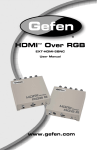
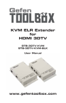
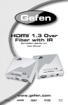
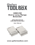
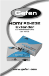
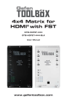
EXT-HDMI1.3-1FO
User Manual
www.gefen.com
ASKING FOR ASSISTANCE
Technical Support:
Telephone
Fax
(818) 772-9100
(800) 545-6900
(818) 772-9120
Technical Support Hours:
8:00 AM to 5:00 PM Monday through Friday, Pacific Time
Write To:
Gefen, LLC
c/o Customer Service
20600 Nordhoff St
Chatsworth, CA 91311
www.gefen.com
[email protected]
Notice
Gefen, LLC reserves the right to make changes in the hardware, packaging and
any accompanying documentation without prior written notice.
HDMI, the HDMI Logo, and High-Definition Multimedia Interface are
trademarks or registered trademarks of HDMI Licensing in the United States and
other countries.
Extender for HDMI 1.3 Over One Fiber with IR is a trademark of Gefen, LLC
© 2011 Gefen, LLC. All rights reserved.
All trademarks are the property of their respective owners.
Rev A6
CONTENTS
1
Introduction
2
Operation Notes
3
Features
4
Sender Unit Layout
5
6
7
8
Sender Unit Descriptions
Receiver Unit Layout
Receiver Unit Descriptions
Connecting and Operating the Extender
8
Wiring Diagram
9
DIP Switch Configuration
10
DIP Switches
11
Local EDID / External (Pass-Through) EDID Modes
11
Deep Color
11
Calibration Procedure
12 Specifications
13 Warranty
INTRODUCTION
Congratulations on your purchase of the Extender for HDMI 1.3 Over One Fiber
with IR. Your complete satisfaction is very important to us.
Gefen
Gefen delivers innovative, progressive computer and electronics add-on solutions
that harness integration, extension, distribution and conversion technologies.
Gefen’s reliable, plug-and-play products supplement cross-platform computer
systems, professional audio/video environments and HDTV systems of all sizes
with hard-working solutions that are easy to implement and simple to operate.
The Gefen Extender for HDMI 1.3 Over One Fiber with IR
The Gefen Extender for HDMI 1.3 Over One Fiber with IR transmits 1080p Full
HD in Deep Color and multi-channel digital audio up to 1000 feet (330 meters)
over a single-strand SC fiber optic cable. Extraordinary distances can be
achieved using this feature-rich device.
1080p Full HD with Deep Color is instantaneously displayed at the remote
location. This product also eliminates EMI (electromagnetic interference), picture
cut-outs and screen distortions traditionally seen with copper-based HDMI
extenders.
A multi-channel digital audio experience is delivered with Dolby TrueHD® and
DTS-HD® Master Audio™.
A single-strand SC fiber cable carries the IR back channel and bidirectional
RS-232, facilitating convenient local control of the video source devices.
How It Works
Connect the Sender Unit to the high definition source using the provided HDMI
cable. Connect the Receiver Unit to an HDTV display using another HDMI cable.
Run a single strand of SC fiber optic cable from Sender Unit to the Receiver Unit.
Power up both the Sender Unit and the Receiver Unit. A clean and vibrant HDMI
A/V signal will appear on the display along with clear and crisp digital audio.
Send IR commands from the IR Remote Control back to A/V source equipment
via the IR back channel using the fiber optic cable connecting the Sender Unit
to the Receiver Unit. The Sender Unit has an IR blaster port, enabling wide IR
signal coverage in an A/V equipment room.
In addition, RS-232 commands from a home automation system or PC can be
used to control the source device or any other RS-232 device using the ports on
the Sender Unit and the Receiver Unit.
1
OPERATION NOTES
READ THESE NOTES BEFORE INSTALLING OR
OPERATING THE EXTENDER FOR HDMI 1.3 OVER ONE FIBER WITH IR
•
IR data repeater functionality is single-directional. IR data can only be
transmitted from the Receiving unit back to the Sending unit. IR data cannot
be transmitted from the Sending unit to the Receiving unit.
•
Use one SC-terminated multi-mode fiber optic cable to operate the HDMI 1.3
Over One Fiber with IR.
•
1080p video may be extended up to 1000 feet (300m), depending on the
type of fiber optic cable used. The following maximum extension distances
will be possible depending on the types of fiber optic cabling that are used:
•
•
100m (330 ft) on 62.5/125 μm (OM1) multi-mode SC fiber
•
300m (1000 ft) on 50/125 μm (OM3) multi-mode SC fiber
RS-232 data is bi-directional for direct commands and echo function or
status information.
IMPORTANT CALIBRATION PROCEDURE
These steps must be followed when setting up the Gefen Extender for HDMI 1.3
over one Fiber with IR for the first time.
•
Connect the SC fiber optic cable between the Sender unit and the Receiver
unit.
•
Set DIP switch 3 on both the Sender unit and the Receiver unit to the OFF
position.
•
Apply power to the source and to both the Sender and Receiver units. The
LED indicators on both the Sender unit and Receiver unit will alternate from
red to green during the calibration process. The calibration process can take
up to 120 seconds to complete.
•
After the calibration process has finished, the LED indicators on both the
Sender unit and the Receiver unit will be solid green. Set DIP switch 3 to
the ON position on both the Sender unit and the Receiver unit to lock the
calibration settings.
NOTE: When changing fiber optic cables, the calibration procedure must be
repeated. See page 11 for details on the calibration procedure.
2
FEATURES
HDMI 1.3 Features
•
•
•
•
•
225 MHz (up to 12 bit YUV 444 @ 1080p)
Deep Color
Dolby TrueHD and DTS-HD Master Audio
Lip-Sync
CEC Protocol Pass-Through
Features
•
Supports video resolutions up to 1080p,1920 x 1200 and 2K
•
3DTV Pass-Through
•
Delivers highest quality signal of any HDMI extension method
•
EDID Detection/Adjustment for rapid integration of source and displays
•
Extends HDMI and RS-232 up to 1000 feet (300m)
•
Uses widely available single-strand multi-mode SC fiber optic cable
•
Immune to electromagnetic interference (EMI)
•
HDCP Compliant
Package Includes
(1) Extender for HDMI 1.3 Over One Fiber with IR - Sender unit
(1) Extender for HDMI 1.3 Over One Fiber with IR - Receiver unit
(2) Mounting Plates
(1) 6 ft HDMI Cable (M-M)
(1) 6 ft DB9 Serial Cable (M-F)
(2) 5V DC Locking Power Supplies
(1) User Manual
3
SENDER UNIT LAYOUT
Front
2
5
3
1
4
Back
7
6
4
SENDER UNIT DESCRIPTIONS
1
Power Indicator
This two-color LED will turn bright red once the included 5V DC locking power
supply has been properly connected to the unit and the locking power supply
has been connected to an available wall outlet. This LED will turn bright green
once the Sender unit and Receiver unit are communicating correctly.
2
Calibration Indicator
This LED will alternate from red to green during the calibration procedure. The
LED will turn solid green once the calibration procedure has been completed.
3
IR Blaster Port
Connect an IR Blaster cable (Gefen part # EXT-2IREMIT) to this port.
4
Locking HDMI Input Port
Connect a Hi-Def source to this HDMI port.
5
RS-232 Input Port
Connect the controlling device to this port.
6
Fiber Optic Connector (SC-Type)
This connector accepts 1 strand of SC-terminated fiber optic cable that will link
the Sender Unit and Receiver Unit together. The Gefen Extender for HDMI 1.3
Over One Fiber with IR will only accept multi-mode fiber optic cabling.
7
5V DC Locking Power Connector
Connect the included 5V DC Locking Power Supply to this receptacle.
5
RECEIVER UNIT LAYOUT
Front
1
4
2
3
5
Back
6
7
8
6
RECEIVER UNIT DESCRIPTIONS
1
RS-232 Output Port
Connect a controlling device to this port.
2
Locking HDMI Output Port
Connect a HDTV display to this HDMI port
3
IR Window
Receives signals from the Hi-Def source IR remote control unit. The IR signals
are sent back to the source device, when using an IR Blaster.
4
Calibration Indicator
This LED will alternate from red to green during the calibration procedure. The
LED will turn solid green once the calibration procedure has been completed.
5
Power Indicator
This two-color LED will turn bright red once the included 5V DC locking power
supply has been properly connected to the unit and the locking power supply
has been connected to an available wall outlet. This LED will turn bright green
once the Sender unit and Receiver unit are communicating correctly.
6
5V DC Locking Power Connector
Connect the included 5V DC Locking Power Supply to this receptacle.
7
IR Extender Port
Connect an IR Extender cable (Gefen part # EXT-RMT-EXTIR) to this port.
8
Fiber Optic Connector (SC-Type)
This connector accepts 1 strand of SC-terminated fiber optic cable that will link
the Sender Unit and Receiver Unit together. The Gefen Extender for HDMI 1.3
Over One Fiber with IR will only accept multi-mode fiber optic cabling.
7
CONNECTING AND OPERATING THE
GEFEN EXTENDER FOR HDMI 1.3 OVER ONE FIBER WITH IR
How to Connect the Extender for HDMI 1.3 over One Fiber with IR
1.
Connect a Hi-Def source to the Sender Unit using the included Locking HDMI
cable. Connect the HDTV display to the Receiver Unit with a user-supplied
HDMI cable.
2.
Connect an SC-terminated fiber optic cable to the Sender Unit. Connect the
opposite end of the fiber cable to the Receiver Unit.
3.
OPTIONAL: Connect an RS-232 cable from the RS-232 serial port on the
controlling device to the RS-232 port on the Sender Unit. Connect another
RS-232 serial cable from the RS-232 port on the Receiver Unit to the RS232 port of the RS-232 device.
4.
IMPORTANT: Before connecting the power supplies to the Sender Unit and
the Receiver Unit, see page 11 for information on calibrating the Sender Unit
and Receiver Unit.
After the Sender Unit and Receiver Unit have been properly calibrated, a vibrant
HDTV HD picture will be seen, along with multichannel digital audio (if the display
supports audio).
Wiring Diagram for the Extender for HDMI 1.3 over One Fiber with IR
SC-SC FIBER OPTIC CABLE
(Up to 1,000 ft)
HDMI CABLE
RS-232
IR
IR Emitter
IR Extender
Hi-Def Source
Receiver
Sender
RS-232 Controller
HD Display
with RS-232 Control
EXT-HDMI1.3-1FO
8
DIP SWITCH CONFIGURATION
DIP Switches
On the bottom of the Sender Unit and Receiver Unit are a bank of four (4) DIP
switches. These DIP switches provide control over EDID, Deep Color, and unit
Calibration.
Remove the strip of tape to expose the DIP switches. To change the DIP switch
settings, move the appropriate DIP switch to its ON or OFF position using a small
pointed object. The DIP switches and their functions are shown below.
Sender Unit DIP switches
DIP Switch
Function
1
EDID Mode: Local (OFF) or External (ON)
2
Deep Color Mode: 12-bit (OFF) or 8-bit (ON)
3
Calibration Mode: On (OFF) or Lock (ON)
4
NOT USED
Receiver Unit DIP switches
DIP Switch
Function
1
NOT USED
2
NOT USED
3
Calibration Mode: On (OFF) or Lock (ON)
4
NOT USED
9
DIP SWITCH CONFIGURATION
DIP 1 - EDID Mode
•
OFF - Local EDID
When Local EDID mode is used, the EDID will be assembled by copying
all video and audio features of the connected device. Deep Color support
will be manually controlled: If Deep Color is supported by the display(s),
DIP 2 should be set to the ON position (see DIP 2 - Deep Color, below). By
default, the unit is shipped with DIP 1 in the OFF position.
•
ON - Pass-Through EDID
Allows all video and audio features of the connected devices to be passed to
the source device without control over Deep Color.
DIP 2* - Deep Color
NOTE: DIP switch 2 is only functional when DIP switch 1 is set to the OFF position.
•
OFF - Enables Deep Color support (12-bit color)
Enables Deep Color support. In Pass-through EDID Mode, setting DIP2 =
OFF has no effect since all EDID information is passed through.
•
ON - Forces 8-bit Color
Disables Deep Color in the EDID. Deep Color management is only available
when Local EDID is being used.
DIP 3 - Calibration Mode
•
OFF - Enables Calibration Mode
Enables Calibration Mode. Make sure to set DIP switch 3 on both the
Sender Unit and Receiver Unit when calibrating the Extenders. See page 11
for details.
•
ON - Calibration Mode Lock
Locks the calibration settings. Set DIP switch 3 on both the Sender Unit and
Receiver Unit to the ON position after the calibration process has completed.
See page 11 for details on the calibration process.
10
DIP SWITCH CONFIGURATION
Calibrating the Sender Unit and Receiver Unit
IMPORTANT: Before beginning the calibration process, make sure that the
Sender Unit and Receiver are not powered.
1.
Make sure DIP switch 3 on both the Sender Unit and the Receiver Unit are in
the OFF position (see page 9).
2.
Connect one end of the fiber cable to the Sender Unit. Connect the other
end of the fiber cable to the Receiver Unit.
3.
Make sure DIP switch 3 on both the Sender Unit and the Receiver Unit are in
the OFF position (see page 9).
4.
Connect the 5V DC Locking Power Supplies to the Sender Unit and the
Receiver Unit. Do not overtighten the locking connectors. Plug the power
cord into an available electrical outlet.
The LED indicators on both the Sender Unit and Receiver Unit will alternate from
red to green during the calibration process. The calibration process can take up
to 120 seconds to complete.
After the calibration process has finished, the LED indicators on both the Sender
unit and the Receiver unit will turn solid green. Set DIP switch 3 to the ON
position on both the Sender Unit and the Receiver Unit to lock the calibration
settings.
NOTE: If the fiber optic cable is changed, repeat the calibration procedure.
Troubleshooting Procedure
•
If the Sender Unit and Receiver Unit did not complete the calibration
process, the indicator LEDs on both Sender Unit and Receiver Unit will be
red. Check the fiber connections carefully and cycle the power on both the
Sender Unit and the Receiver Unit and repeat the calibration procedure.
•
When the indicator LED at one unit is GREEN and the other is RED,
cycle power on the unit with the RED indicator. It is also recommended to
cycle power on both the Sender Unit and the Receiver Unit to perform a full
calibration.
•
If the calibration procedure continues to fail, contact Gefen Technical
Support under the Asking For Assistance section at the beginning of this
manual.
11
SPECIFICATIONS
Video Amplifier Bandwidth ........................................................................ 225 MHz
Maximum Resolutions Supported: ..................................1080p60, 1920x1200, 2K
Input Video Signal .............................................................................. 1.2 Volts p-p
Input DDC Signal .......................................................................... 5 Volts p-p (TTL)
HDMI Input/Output Connector ......................................................... Type A, 19-pin
RS-232 Input/Output Connector........................................................................DB9
RS-232 Data Transmission Rate ............................................115,200 kbps (max.)
LED Indicator (Power ON/OFF) ......................................2-color LED (red / green)
LED Indicator (Fiber Calibration) .....................................2-color LED (red / green)
IR Modulation Frequency: ...........................................................................38 KHz
IR Blaster: .................................................................................3.5mm Mini-Stereo
Link Connector ................................................................ SC Fiber Optic x 1 cable
Power Supply ............................................................................................... 5V DC
Power Consumption .................................................................. 10W per unit (max)
Dimensions .......................................................................... 4.2”W x 1.2”H x 3.8”D
Shipping Weight ............................................................................................. 5 lbs.
Compliancy:
RoHS and CE Certified; Complies with US/EU Standards
HDMI 1.3, HDMI 1.2, HDCP 1.1 and DVI 1.0 Compliant.
UL-Certified Power Supply.
12
WARRANTY
Gefen warrants the equipment it manufactures to be free from defects in material
and workmanship.
If equipment fails because of such defects and Gefen is notified within two (2)
years from the date of shipment, Gefen will, at its option, repair or replace the
equipment, provided that the equipment has not been subjected to mechanical,
electrical, or other abuse or modifications. Equipment that fails under conditions
other than those covered will be repaired at the current price of parts and labor in
effect at the time of repair. Such repairs are warranted for ninety (90) days from
the day of reshipment to the Buyer.
This warranty is in lieu of all other warranties expressed or implied, including
without limitation, any implied warranty or merchantability or fitness for any
particular purpose, all of which are expressly disclaimed.
1.
Proof of sale may be required in order to claim warranty.
2.
Customers outside the US are responsible for shipping charges to and from
Gefen.
3.
Copper cables are limited to a 30 day warranty and cables must be in their
original condition.
The information in this manual has been carefully checked and is believed to
be accurate. However, Gefen assumes no responsibility for any inaccuracies
that may be contained in this manual. In no event will Gefen be liable for
direct, indirect, special, incidental, or consequential damages resulting from
any defect or omission in this manual, even if advised of the possibility of such
damages. The technical information contained herein regarding the features and
specifications is subject to change without notice.
For the latest warranty coverage information, refer to the Warranty and Return
Policy under the Support section of the Gefen Web site at www.gefen.com.
PRODUCT REGISTRATION
Please register your product online by visiting the Register Product page
under the Support section of the Gefen Web site.
13
Rev A6
20600 Nordhoff St., Chatsworth CA 91311
1-800-545-6900
818-772-9100
www.gefen.com
Pb
This product uses UL listed power supplies.
fax: 818-772-9120
[email protected]