1
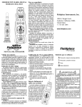
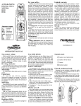
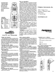
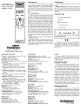
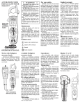
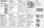
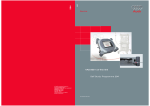
DIGITAL STICK METER
MODELS: HS32, HS33
For your safety...
Limited warranty
General: Disconnect the test leads before opening
the case. Inspect the test leads for damage to the
insulation or exposed metal. Replace if suspect.
Never ground yourself when taking electrical measurements. Do not touch exposed metal pipes, outlets,
fixtures, etc., which might be at ground potential.
Keep your body isolated from ground by using dry
clothing, rubber shoes, rubber mats, or any approved
insulating material. When disconnecting from a circuit, disconnect the "RED" lead first, then the common lead. Work with others. Use one hand for testing. Turn off power to the circuit under test before cutting, unsoldering, or breaking the circuit. Keep your
fingers behind the finger guards on the probes. Do
not measure resistance when circuit is powered. Do
not apply more than rated voltage between input and
ground.
All voltage tests: All voltage ranges will withstand
up to 600V. Do not apply more than 600VDC or
600VAC.
AC tests: Disconnect the meter from the circuit
before turning any inductor off, including motors,
transformers, and solenoids. High voltage transients
can damage the meter beyond repair. Do not use
during electrical storms.
This meter is warranted against defects in material or workmanship for one years from date of purchase. Fieldpiece will replace or repair the defective
unit, at its option, subject to verification of the defect.
This warranty does not apply to defects resulting
from abuse, neglect, accident, unauthorized repair,
alteration, or unreasonable use of the instrument.
Any implied warranties arising from the sale of a
Fieldpiece product, including but not limited to
implied warranties of merchantability and fitness for a
particular purpose, are limited to the above.
Fieldpiece shall not be liable for loss of use of the
instrument or other incidental or consequential damages, expenses, or economic loss, or for any claim of
such damage, expenses, or economic loss.
State laws vary. The above limitations or exclusions may not apply to you.
Maintenance
Built-in magnetic
hanger.
Service
Call Fieldpiece Instruments for one-price-fix-all warranty service pricing. Send check or money order for
the amount quoted. Send the meter freight prepaid to
Fieldpiece Instruments. Send proof of date and location of purchase for in-warranty service. The meter
will be repaired or replaced, at the option of
Fieldpiece, and returned via least cost transportation.
Clean the exterior with clean dry cloth. Do not use
liquid.
Battery replacement: When the multimeter displays "
" the battery must be replaced. Disconnect
and unplug leads, turn meter off, and remove the battery cover. Replace the battery with a NEDA type
1604 9V battery.
OPERATOR’S MANUAL
Non-contact voltage
With the red NCV tab on the tip of the meter close
to an AC voltage, press and hold the NCV button.
The NCV LED will light and the beeper will beep. The
closer you get to AC voltage, the louder the beep.
The NCV function is sensitive enough to detect
24VAC on thermostats.
Hi voltage indicator
In any VAC/VDC range, when you touch a voltage
greater than 30V, the beeper will beep and the red HiV LED will blink. BE CAREFUL!
Capacitance
For motor-start and motor-run capacitors.
Disconnect the capacitor from power first. Short the
terminals to discharge the capacitors. Disconnect
any resistors that might be between the terminals of
the capacitor.
MIN/MAX and data HOLD
Press MIN/MAX once to begin recording MIN and
MAX. Press MIN/MAX to select current reading’s MIN
or MAX. Hold down for 2 seconds to exit MIN/MAX
function. Press HOLD to hold data.
Temperature (HS33)
Plug any K-type thermocouple directly into the
meter to measure temperature. Temperature measurement will be accurate even in fast changing environments because of excellent temperature compensation. One thermocouple is included. No adapter is
required.
www.fieldpiece.com.
Field °F calibration (HS33)
For accuracies of ±°F, calibrate the HS33 to a
known temperature. A glass of stabilized ice water is
very close to 32°F (0°C) and is usually very convenient but any known temperature can be used.
1. Select the 200°F range.
2. Remove back case and hold the battery in place
with a rubber band so terminals are touching.
3. Stabilize a large cup of ice water.
4. Immerse the thermocouple probe and let it stabilize.
5. Adjust VR3 (below battery) to get close to 32°F
(0°C) then adjust VR1 (right of battery) to get
within 0.1°F (0.1°C) of 32.0°F (0.0°C).
6. To calibrate in °C, close the jumper that is just
below VR1.
Easily detect the live wire
The non-contact voltage feature
can be used in conjuction with one
probe tip to find which wire is live.
With meter set to OFF, place
probe tip in red plug as shown
below. Hold down NCV while
touching each wire, a noticably louder buzz will sound
when you’ve touched a live
wire.
Symbols used:
Caution, risk of electric shock
! Caution, refer to manual.
Ground
Double insulation
!
WARNINGS
!
DISCONNECT AND UNPLUG TEST LEADS
before opening case.
TEST NCV FUNCTION ON KNOWN LIVE
WIRE before using.
DO NOT APPLY VOLTAGE greater than
30VAC or 60VDC to the thermocouple or the
jacks when the rotary dial is on OF.
REMOVE THE THERMOCOUPLE when taking voltage measurements.
DISCONNECT THE TEST LEADS when taking
temperature measurements.
DO NOT APPLY VOLTAGE TO THE JACKS
when the rotary dial is on microamps. Even low
voltages can cause a current overload and blow
the fuse. Replace blown fuse to regain function.
Attach to Fieldpiece accessory head
Connect your Fieldpiece accessory head directly
to the top of HS series and switch to range indicated
by head.
P/N: 7000-1659
v16
Voltage
Temperature (HS33)
Disconnect test
leads from voltage before plugging in thermocouple!
Insure the temperature
being
measured is stable.
Maintain good contact between the
thermocouple and
what's being measured.
Capacitance
Resistance
The k-type thermocouple
supplied is designed with a
“wrap tab” to keep the wire
out of the way when not
needed. Just wrap the wire
around tab and pull through
the hole at the top to keep in
place as shown to the left. No
more clutter when stored.
For DC voltage, set the meter to the VDC parameter instead of VAC as shown above.
For all ranges choose a range just above the value
you expect. If display reads “OL” (overload), select a
higher range. If display shows less than three numbers, select a lower range for better resolution.
SPECIFICATIONS
DC volts
Display: 3½ digit liquid crystal display (LCD) with a
maximum reading of 1999.
Overrange: "OL" mark indication.
Auto power off: 60 minutes.
Operating environment: 32 to 122°F (0 to 50°C) at
<70% R.H.
Storage temperature: -4 to 140°F (-20 to 60°C), 0
to 80% R.H. with battery removed.
Accuracy: Specifications good in ambient conditions of 73°F ±9°F (23°C ±5°C), <75% relative
humidity.
Temperature Coefficient: 0.1×(specified accuracy)
per °F/°C. (32 to 64°F (0 to 18°C), 82 to 122°F
(28 to 50°C)).
Power: Single standard 9-volt battery, NEDA 1604,
JIS 006P, IEC 6F22.
Battery life: 300 hours typical with alkaline.
Accessories: One pair test leads, one pair alligator
clips, k-type thermocouple (HS33), 9V battery
(installed), and operating instructions.
Safety: UL, CE, Cat III 600V, UL3111,
IEC/EN61010-1, C-Tick certified.
Ranges: 200mV, 2000mV, 20V(HS32), 200V
Resolution: 0.1mV
Accuracy: ±(0.5% rdg + 1 dgt)
Input impedance: 560kΩ on V inputs, 10MΩ on
mV input
Overload protection: 600VDC or AC rms,
500VDC/350VAC rms 15 sec on 200mV range
Transient protection: 6kV for 10μ sec
Test current: ∼1.0mA
Accuracy: ±(1.5% rdg + 3 dgts)
Open circuit volts: 3.0VDC typical
Overload protection: 500VDC or AC rms
Continuity
Audible indication: Less than 100Ω
Response time: 100ms
Green LED will be on continuously.
Overload protection: 500VDC or AC rms
Capacitance
Range: 200μF
Resolution: 0.1μF
Accuracy: ±(3% rdg + 5 dgts)
Overload protection: 500VDC or AC rms
300V
400A
CLAMP
CAT.III
AC Current
Clamp
1AAC / 1mVAC
400AAC MAX
!
ACH4
The velcro strip supplied is
intended to be used as shown
on the right. Tie thermocouple
like this and wrap velcro
around surface to make sure
bare wires are in close contact with surface being measured. This is especially helpfull when taking pipe temps.
Selecting Ranges
Diode test
Works with Fieldpiece accessory
heads!
AC volts (50Hz - 500Hz)
Ranges: 200mV, 200V, 600V
Resolution: 0.1mV
Accuracy: ±(1.2% rdg + 3 dgts) ±(2.0% rdg + 5
dgts) on 600V range
Input impedance: 560kΩ on V input, 10MΩ on mV
input
Overload protection: 600V DC or AC rms
Transient protection: 6kV for 10μ sec
Resistance
Ranges: 200Ω, 200kΩ
Resolution: 0.1Ω
Accuracy: ±(1.0% rdg + 4 dgts)
Open circuit volts: 0.3VDC typical, (3.0VDC on
200Ω range)
Overload protection: 500VDC or AC rms
Temperature (HS33)
Range: -30 to 200°F (-34 to 93°C)
Resolution: 0.1°F/°C
Accuracy: ±1°F, 32 to 120°F (0 to 48°C),
±1% + 1.5°F, -4 to 200°F (-20 to 93°C),
±2% + 3°F, -30 to -4°F (-34 to -20°C).
Sensor type: K-type thermocouple
Overload protection: 60 VDC or 30 VAC rms
(1)
(2)
Connect to Fieldpiece accessory heads by simply
attaching them to the top of meter (1) or attach
remotely through leads (2). For most heads, move
dial to range shown (1). For the AAC clamp (ACH4),
move dial to VAC range (2).
Available Fieldpiece access. heads
There is a Fieldpiece accessory head available for
just about any job. There are heads to measure temperature, RH%, wet bulb, dew point, vacuum
(microns of mercury), manometer (inches of water
column), amps AC&DC, high voltage, CO, CO2, air
velocity, and many more.
Using & storing test leads
Because the wire insulation is silicone the leads
will stay flexible in cold weather and will not melt if
bumped by a soldering iron.
Disconnect top half of test lead and plug tip directly into meter to make voltage testing easy. Use with
included alligator clip (ASA2) as shown for even easier operation.
For convenient lead storage, wrap the leads as
shown. Pull leads around front between overhanging
tips, twist, and pull over one of the lead plugs.