1
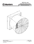
Vortex® Fans
9" - 26" Direct Drive
VX09P • VX14F • VX16F • VX18F • VX24F • VX26F
R
R
Ventilation Systems
9"
14" - 24"
26"
Munters Corporation
4215 Legion Dr. Mason, MI 48854-1036 USA
Ph. (517) 676-7070 Fax (517) 676-7078
www.munters.us/aerotech
FORM: QM1105
May 2011
Page 1 of 13
USER'S MANUAL and INSTALLATION GUIDE
TABLE OF CONTENTS
Section
Page
Unpacking the Equipment............................................................................................3
Fan Dimensions...........................................................................................................3
Fan Installation...........................................................................................................4-6
Electrical Wiring............................................................................................................7
Operation...................................................................................................................8-10
Maintenance................................................................................................................10
Winterizing Fan...........................................................................................................11
Troubleshooting...........................................................................................................11
Exploded View..........................................................................................................12-13
THANK YOU
Thank you for purchasing a Vortex Direct Drive Fan from Munters. Munters equipment is
designed to be the highest performing, highest quality equipment you can buy. With the proper
installation and maintenance it will provide many years of service.
PLEASE NOTE
To achieve maximum performance and insure long life from your Munters fan it is essential that
it be installed and maintained properly. Please read all instructions carefully before beginning
installation.
WARRANTY
For Warranty claims information see the "Warranty Claims and Return Policy" form QM1021
available from the Aerotech Ventilation System, Munters Corporation office at 1-800-227-2376
or by e-mail at [email protected].
Conditions and Limitations:
• Products and Systems involved in a warranty claim under the "Warranty Claims and Return
Policy" shall have been properly installed, maintained and operated under competent
supervision, according to the instructions provided by Aerotech Ventilation Systems,
Munters Corporation.
• Malfunction or failure resulting from misuse, abuse, negligence, alteration, accident or lack
of proper installation or maintenance shall not be considered a defect under the Warranty.
Munters Corporation
4215 Legion Dr. Mason, MI 48854-1036 USA
Ph. (517) 676-7070 Fax (517) 676-7078
www.munters.us/aerotech
FORM: QM1105
May 2011
Page 2 of 13
Unpacking the equipment
Before beginning installation, check the overall condition of the equipment. Remove packing
materials, and examine all components for signs of shipping damage. Any shipping damage is the
customer's responsibility and should be reported immediately to the freight carrier.
Each Fan Includes:
1 - Direct Drive Fan
1 - Hardware Package (HP1145)
[A]
HP1145 for Vortex Direct Drive fan
[A]…..8 - #14 x 1.5” Lag Screws, S.S.
Fan Specifications:
Power:120 or 240 VAC
Phase:1
Hertz: 60
FAN DIMENsIONS
C
E
A
B
D
FAN
DIA.
NO. OF
BLADES
A
B
C
D
E
9"
14"
16"
18"
24"
26"
6
7
4
5
4
3
23/4"
45/16"
43/4"
43/4"
53/4"
51/2"
91/2"
12"
16"
16"
20"
22"
15"
205/8"
251/2"
251/2"
311/2"
33"
12"
173/8"
221/4"
221/4"
281/4"
293/4"
111/2"
165/8"
183/4"
183/4"
193/4"
181/8"
G
B
C
A
F
CAT.
NO.
VX09P
VX14F
VX16F
VX18F
VX24F
VX26F
Munters Corporation
4215 Legion Dr. Mason, MI 48854-1036 USA
Ph. (517) 676-7070 Fax (517) 676-7078
www.munters.us/aerotech
F
G
21/2"
91/2"OD
7"
145/8"OD
1
5 /2" 1611/16"OD
51/2" 1811/16"OD
51/2" 2411/16"OD
107/16"
27"OD
Wall Opening
(I.D., framed)
121/2" sq.
171/2" sq.
221/2" sq.
221/2" sq.
281/2" sq.
301/4" sq.
FORM: QM1105
May 2011
Page 3 of 13
INSTALLATION INSTRUCTIONS
Step 1
Construct the framed opening to correct size according to the above chart and your fan size.
See Figure 1.
If a 9" Vortex fan was purchased, proceed to Step 7.
If a PV or PZ shutter was purchased proceed to step 2, if a PT shutter was purchased proceed to step 5.
8"
Min.
Framing
Wall
Opening
(see chart on
previous page)
Wall
Opening
(see chart on
previous page)
12"
Ceiling
Figure 1
FAN WITH 'PV' OR 'PZ' STYLE SHUTTER
!
WARNING
Rotating fan blades.
Operation of fan without
wire screens or guards
may result in direct
contact with blades and
cause severe personal
injury or death.
Step 2
Insert fan into the framed opening from the
inside and fasten with (8) Lag Screws [A]
(provided). Flash and caulk around opening.
See Figure 2.
#14 x 1.5" Lag
Screws [A]
Vortex Fan
Step 3
Outlet of fan comes unguarded, it is recommended that an Aerotech discharge cone
with guard, a fan hood with guard or a guard
by others is installed on outlet of fan at this
time.
2 x 4 Framing
OUTSIDE
INSIDE
Figure 2
Munters Corporation
4215 Legion Dr. Mason, MI 48854-1036 USA
Ph. (517) 676-7070 Fax (517) 676-7078
www.munters.us/aerotech
FORM: QM1105
May 2011
Page 4 of 13
Step 4
Slide shutter into back of fan. See Figure 3A. Fasten
shutter in place by rotating the side and top shutter clips
over the shutter flanges. See Figure 3B.
Installation is now complete, proceed to Electrical Wiring
Section.
Airfoil
Shutter
Figure 3A
Figure 3B
FAN WITH 'PT' STYLE SHUTTER
Step 5
Insert fan into the framed opening from the inside and fasten with (8) Lag Screws [A] (provided). Flash and caulk
around opening. See Figure 4. If fan and shutter needs to be mounted flush to inside wall, See Figure 5 for framing
details.
Wall Framing
4" Minimum Framing for fan,
Top and Sides
Wall Opening. See Chart
#14 x 1.5" Lag
Screws [A]
Vortex Fan
2 x 4 Framing
Fan Framed
Opening Chart
14"
16"
18"
24"
26"
171⁄2" sq.
221⁄2" sq.
221⁄2" sq.
281⁄2" sq.
301/4" sq.
2" Minimum Framing for fan, Bottom
Wall Framing
Figure 4
Munters Corporation
4215 Legion Dr. Mason, MI 48854-1036 USA
Ph. (517) 676-7070 Fax (517) 676-7078
www.munters.us/aerotech
Figure 5
FORM: QM1105
May 2011
Page 5 of 13
FAN WITH 'PT' STYLE SHUTTER
Step 6
Insert PT shutter into fan. See Figure 6A. Fasten shutter in place by rotating the side and top shutter clips over the
shutter flanges. See figure 6B.
PT Shutter
Figure 6B
Figure 6A
NOTE: Shutter protrudes from fan 215⁄16". Provide adequate guarding to protect shutter.
Installation is now complete, proceed to Electrical Wiring Section.
9" Vortex Fan Instructions:
Step 7
Mount the fan to the framed opening from the outside of
the building and fasten with (8) Fastner [A]. Be sure fan
is mounted upright. Flash and caulk around opening. See
Figure 7.
Step 8
If fan was purchased with shutter, mount shutter to inside
of building. Fasten shutter in place with (6) Tapping
screws (not provided).
AT09Z Fan
#14 x 1.5" Lag Screw [A]
Flash and Caulk
Outside
121/2"
Wall Opening
2 x 4 Framing
PZ09 Shutter
Inside
Figure 7
AT09Z Fan
Step 9
If fan needs to be mounted from the inside, install the
fan through the wall and fasten using (8) Fastener [A]
(provided). Then install 11/2" spacer strips around the
opening in the back of the fan before fastening shutter in
place. See Figure 8.
11/2" x 11/2" Spacer
PZ09 Shutter
Munters Corporation
4215 Legion Dr. Mason, MI 48854-1036 USA
Ph. (517) 676-7070 Fax (517) 676-7078
www.munters.us/aerotech
Figure 8
FORM: QM1105
May 2011
Page 6 of 13
ELECTRICAL WIRING
Recommended Wire Routing:
As the power cable exits the back of motor form
a drip loop and then run power cable down along
motor mount and "Zip" tie the cable to motor mount
to prevent cable from getting tangled in the prop.
See Figure 9. Then run the cable out the drain hole
to the circuit breaker or control panel.
Figure 9
!
WARNING
High Voltage,
disconnect power
before installation.
KEY:
L1= Line 1
L2= Line 2
G = Ground
All wiring should be installed in accordance with National, State, and Local electrical codes.
Fans used to ventilate livestock buildings or other rooms where continuous air movement is
essential should be connected to individual electrical circuits, with a minimum of two circuits
per room. For electrical connection requirements, refer to diagram on motor nameplate and
to information enclosed with the Aerotech environmental control to be used.
Motor overload protection should be provided for each fan. A Circuit Breaker Switch or slow
blow motor type fuses must be used See Figure 10. See Aerotech form QM1400 for proper
size. NOTE: A safety cut-off switch should be located adjacent to each fan.
120 or 240 VAC
Power Supply for Fan
H = Hot
N = Neutral
NOTE: Information in parenthesis
refers to 120 VAC control.
Munters Corporation
4215 Legion Dr. Mason, MI 48854-1036 USA
Ph. (517) 676-7070 Fax (517) 676-7078
www.munters.us/aerotech
L1 (H)
L1 (H)
T1 (H)
T1 (H)
L2 (N)
L2 (N)
T2 (N)
T2 (N)
G
G
120 or 240 VAC
Power Out to Fan
Figure 10
Motor Overload Protection with Disconnect
(SY2000 or Equivalent)
FORM: QM1105
May 2011
Page 7 of 13
OPERATION
!
1) INITIAL START-UP: With electrical power off, verify that the fan propeller turns
freely and that all fasteners are secure. Turn on electrical power and confirm that the fan operates smoothly.
WARNING
2) ADJUSTMENTS: Set the fan control to the temperature shown on your Aerotech ventilations system drawing, or to a value which will provide the desired
environmental conditions.
Moving parts,
disconnect power
before servicing.
When variable speed controls are used, the fan's idle speed will need to be set to the recommended minimum airflow rate. Refer to the procedures included with each control. The following table provides airflow rates at various propeller speeds for fans wired for 240 VAC:
A = Fan with cone & shutter
9" Fans
50
100
150
200
250
300
400
500
600
700
800
900
1000
1100
14" Fans
CFM
100
120
150
200
300
400
500
600
800
1000
1200
1600
1950
RPM
970
1120
1290
1490
1690
1870
1930
1990
2150
2330
2570
2820
3120
—
A
B = Fan with hood & shutter
0.025" Static Pressure
0.05" Static Pressure
B
C
A
B
C
VOLTS RPM VOLTS RPM VOLTS RPM VOLTS RPM VOLTS RPM VOLTS
950
81
71
80
1100
—
75
—
74
1050
1000
1090
86
77
85
1250
61
79
720
77
1200
1180
1200
91
81
90
1450
63
84
800
83
1350
1380
1270
99
86
96
1660
66
90
880
88
1550
1590
1350
103
90
102
1820
70
95
970
93
1750
1710
1420
107
95
105
1920
79
100
1070
98
1950
1810
1560
115
103
112
2110
91
110
1290
107
2080
2000
1700
124
112
119
2300
104 2160
119
1530
115
2140
1860
134
121
129
2440
116 2270
129
1770
124
2250
2120
135
138
146
2580
130 2480
134
140
2030
2430
2380
149
152
163
144 2690
2770
2310
146
157
2630
2640
165
169
187
158 2920
3020
2580
162
177
2870
2910
197
193
229
189 3180
3230
2830
183
219
3120
3180
228
—
—
221
—
3130
—
—
—
—
A
620
630
640
660
710
760
810
840
940
1030
1130
1370
1640
Munters Corporation
C = Fan with hood & no shutter
4215 Legion Dr. Mason, MI 48854-1036 USA
Ph. (517) 676-7070 Fax (517) 676-7078
www.munters.us/aerotech
620
630
640
670
720
780
840
880
980
1070
1210
1480
–—
B
A
B
141
142
142
143
145
148
151
153
158
163
168
182
218
141
142
142
144
146
149
153
155
160
165
173
197
–—
740
750
760
780
820
860
910
950
1030
1120
1210
1400
1630
150
151
152
153
154
156
158
161
164
168
173
186
230
740
750
760
790
820
870
930
980
1070
1180
1280
1500
–—
150
151
152
153
154
156
160
162
166
170
177
205
–—
FORM: QM1105
May 2011
Page 8 of 13
A = Fan with cone & shutter
CFM
24" Fans
18" Fans
16" Fans
RPM
B = Fan with hood & shutter
0.025" Static Pressure
A
B
VOLTS
VOLTS
RPM
150
175
200
300
400
500
600
800
1000
1250
1500
1750
2000
2500
3000
3170
590
600
610
640
670
700
730
790
850
930
1020
1100
1190
1380
1600
1680
96
96
97
98
100
102
103
107
110
114
119
123
127
136
160
190
600
610
620
660
700
740
780
860
940
1020
1110
1220
1330
1600
—
—
96
97
98
99
102
104
106
111
115
119
124
129
134
160
—
—
RPM
700
710
720
740
770
800
830
880
940
1020
1090
1180
1260
1430
1640
1720
300
400
500
600
700
800
1000
1250
1500
1750
2000
2500
3000
3500
4000
4200
520
550
570
590
620
640
700
760
820
880
940
1070
1210
1380
1570
1650
128
129
130
132
133
134
136
139
143
145
148
154
162
172
190
207
530
560
590
610
640
660
730
800
860
950
1020
1170
1360
1530
—
—
128
129
132
133
134
135
138
141
144
149
152
161
171
188
—
—
1000
1250
1500
1750
2000
2250
2500
2750
3000
3500
4000
4500
5000
5500
6000
—
—
480
500
530
560
580
610
640
690
750
820
890
970
1060
—
—
141
143
145
148
150
152
155
160
166
172
181
195
227
—
—
490
520
550
590
620
660
690
760
820
900
990
1060
—
—
—
142
144
147
151
153
156
160
167
172
183
202
230
—
Munters Corporation
4215 Legion Dr. Mason, MI 48854-1036 USA
Ph. (517) 676-7070 Fax (517) 676-7078
www.munters.us/aerotech
A
0.05" Static Pressure
VOLTS
B
103
103
104
105
106
108
109
112
115
118
123
127
131
140
173
230
RPM
720
730
740
760
780
810
840
920
1000
1100
1200
1350
1460
1630
—
—
VOLTS
660
670
680
710
730
740
780
840
890
940
990
1110
1240
1420
1610
1680
134
135
136
137
138
139
141
144
147
149
152
157
165
175
200
230
670
680
700
740
770
780
830
890
950
1000
1060
1220
1380
1570
—
—
135
136
137
139
140
141
143
147
150
153
155
164
172
190
—
—
490
520
540
560
580
610
630
660
680
730
790
850
920
1000
—
144
146
148
150
152
154
157
159
162
167
172
178
187
204
—
510
530
560
600
630
670
690
720
740
790
860
940
1020
—
—
145
147
150
153
157
160
163
166
168
172
179
191
210
—
—
104
104
105
106
107
108
110
114
117
124
128
136
142
172
—
—
FORM: QM1105
May 2011
Page 9 of 13
CFM
26" Fans
RPM
1250
1500
1750
2000
2250
2500
2750
3000
3500
4000
4500
5000
5500
6000
6500
7000
7500
8000
—
—
480
500
520
540
560
580
620
660
700
740
780
830
880
940
990
1050
A = Fan with cone & shutter
B = Fan with hood & shutter
0.025" Static Pressure
0.05" Static Pressure
B
A
B
A
VOLTS
VOLTS
VOLTS
RPM
RPM
VOLTS
RPM
520
510
147
—
—
148
—
550
530
149
142
—
152
480
580
540
151
144
142
154
500
610
560
153
146
144
158
520
640
580
154
149
146
161
550
650
590
156
152
148
162
580
670
610
158
155
150
164
610
690
630
160
157
152
166
630
730
670
164
163
156
171
680
780
710
168
169
161
177
730
830
740
172
176
165
182
780
880
780
177
183
170
189
840
930
830
182
188
176
199
880
970
870
188
194
181
205
930
1030
920
194
206
188
225
980
—
970
205
225
196
—
1040
1020
—
222
—
208
—
—
—
—
—
—
229
—
—
MAINTENANCE
!
WARNING
The following inspection and cleaning procedures should be performed monthly:
1) INSPECT PROPELLER: Check that propeller is secure on motor shaft and that there are no signs of damage. The blades are of a self-cleaning design and should not require maintenance.
2) CLEAN regularly for best results:
High Voltage,
disconnect power
before servicing.
!
WARNING
• FAN MOTOR: Remove any dust accumulation from motor using a brush or cloth. (DO NOT use a pressure washer). A clean motor will run cooler and last longer. At the same time, verify that the motor is secure in its mount.
• SHUTTER: Carefully clean dust from shutter blades and frame so that shutter opens and closes freely. A brush or cloth should be used.
• GUARD: Clean any dust or feathers from fan guards using a brush. Dirty guards can reduce airflow.
• PIPE HOUSING: Remove dust accumulations from bottom of pipe housing.
Exterior of pipe housing may be cleaned with mild soap and water; abrasives are
not recommended.
Moving parts,
disconnect power
before servicing.
!
WARNING
3) CHECK FASTENERS: For safety, all fasteners should be inspected. Tighten any
loose connections.
4) INSPECT FAN CONTROL: With power disconnected, inspect all electrical connections. Wiring should be secure and in good condition. Remove any dust build-up from
control case and sensor using a soft brush or cloth. NEVER CLEAN ELECTRICAL
EQUIPMENT WITH A PRESSURE WASHER!
Do not power
wash.
Munters Corporation
4215 Legion Dr. Mason, MI 48854-1036 USA
Ph. (517) 676-7070 Fax (517) 676-7078
www.munters.us/aerotech
FORM: QM1105
May 2011
Page 10 of 13
TROUBLE SHOOTING
!
WARNING
High Voltage,
disconnect power
before servicing.
!
WARNING
Moving parts,
disconnect power
before servicing.
SYMPTOM
Fan Not Operating
Fan OperatingInsufficient Airflow
POSSIBLE CAUSES
1. Fan control set above room
Set to a lower temperature
2. Blown fuse or open circuit breaker
Replace fuse or reset breaker
3. Propeller blade contacting fan housing
Realign motor in fan housing
4. Fan control defective
Repair or replace control
5. Motor defective
Repair or replace motor
1. Variable speed control improperly adjusted
See Operation, Step 2 for adjustment guidelines
2. Shutter jammed
3. Guard dirty
Excessive Fan Noise
Clean shutter & fan housing
Clean guard
1. Variable speed control idle speed set to low
Increase idle speed setting
2. Variable speed control defective
Repair or replace control
3. Propeller blade contacting fan panel
Realign motor in fan housing
4. Motor bearing defective
Repair or replace motor
Excessive Fan Vibration 1. Motor loose in mount
Fan never turns off
CORRECTIVE ACTION
Tighten fasteners
2. Propeller damaged
Replace propeller
3. Motor shaft bent
Repair or replace motor
1.Override thermostat set incorrectly
Set to the correct temperature
2. Control set for continuous operation
Set speed control correctly
WINTERIZING FAN
In most climates, it is probable that the ventilation system will never need to operate at a total capacity during
the colder winter months. Consequently, it is advisable to "winterize" those fans which will not be used in cold
weather to avoid unnecessary heat loss and condensation.
To winterize, turn fan control "off". Install the insulated closure panel over the fan intake. If you don't have an
insulated closure panel, a piece of rigid insulation material can be used. Remember the insulation panel
must be removed before warmer weather returns.
NOTE: At least one single speed fan should be left uncovered and with power available to provide air
movement in the event of variable speed control difficulties.
Munters Corporation
4215 Legion Dr. Mason, MI 48854-1036 USA
Ph. (517) 676-7070 Fax (517) 676-7078
www.munters.us/aerotech
FORM: QM1105
May 2011
Page 11 of 13
14" - 26" Vortex Fan
9" Vortex Fan
Vortex Direct Drive
Munters Corporation
4215 Legion Dr. Mason, MI 48854-1036 USA
Ph. (517) 676-7070 Fax (517) 676-7078
www.munters.us/aerotech
FORM: QM1105
May 2011
Page 12 of 13
Vortex Direct Drive
Item
1
Catalog No. Description
Qty.
FH2109
Housing, 9" Vortex Fan, with Labels, PL
1
FH3414
Housing, 14" Vortex Fan, with Clips & Labels, FG
1
FH3416
Housing, 16" Vortex Fan, with Clips & Labels, FG
1
FH3418
Housing, 18" Vortex Fan, with Clips & Labels, FG
1
FH3424
Housing, 24" Vortex Fan, with Clips & Labels, FG
1
FH3127
Housing, 26" Vortex Fan, with Clips & Labels, FG
1
2
FH2119
Right Shutter Clip, AL
3
FP1036SS
Propeller, 9"DD, 6-Blade, Set Screws, AL
FP1031SS
Propeller, 14"DD, 7-Blade, 1⁄2" Bore, Set Screws, AL
FP1038SS
Propeller, 16"DD, 4-Blade, Set Screws, AL
FP1008SS
Propeller, 18"DD, 5-Blade, 1⁄2" Bore, Set Screws, AL
FP1033SS
Propeller, 24"DD, 4-Blade, 1⁄2" Bore, Set Screws, AL
FP1126SS
Propeller, 26.5" DD, 3-Blade, Set Screws, AL
FH1231
9" Fan, Motor Base with Reinforcements, AL
FH1008
14" Fan, Motor Mount, PVC Coated
FH1009
16"/18" Fan, Motor Mount, PVC Coated
FH1010
24" Fan, motor Mount, PVC Coated
FH2526
26" Fan, Motor Mount, PVC Coated
FM1039
9" DD, Motor, 1⁄6 HP, 3350 RPM, 36 Fr., 1 ph., 115V
FM1038
9" DD, Motor, 1⁄6 HP, 3350 RPM, 36 Fr., 1 ph., 230V
FM1010
14" DD, Motor, 1⁄8 HP, 1625 RPM, 48 Fr., 1 ph., 115/230V
FM1043
16" DD, Motor, 1⁄4 HP, 1625 RPM, 48 Fr., 1 ph., 115/230V
FM1009
18" DD, Motor, 1⁄3 HP, 1625 RPM, 48 Fr., 1 ph., 115/230V
FM1008
24"/26" DD, Motor, 1⁄3 HP, 1075 RPM, 48 Fr., 1 ph., 115/230V
FM1070
24"/26" DD, Motor, 1⁄3 HP, 1075 RPM, 48 Fr., 3 ph., 208-230/460V
6
FH2117
Left Shutter Clip, Al (14"-24" fans only)
7
PT0914
Shutter, 163⁄4" SQ., Belted inlet, White Plastic
PT1618
Shutter, 215⁄8" SQ., Belted inlet, White Plastic
PT24
Shutter, 275⁄8" SQ., Belted inlet, White Plastic
PT26
Shutter, 29.4" SQ., Belted inlet, White Plastic
PZ09
Shutter, 117⁄8" SQ., White Plastic
PZ0914
Shutter, 163⁄4" SQ., White Plastic
PZ1618
Shutter, 215⁄8" SQ., White Plastic
PZ24
Shutter, 275⁄8" SQ., White Plastic
PV26
Shutter, 29.4" SQ., White Plastic
2
1
1
1
1
1
1
1
1
1
1
1
1
1
1
1
1
1
1
1
1
1
1
1
1
1
1
1
1
1
4
5
8
9
FH1227
Munters Corporation
9" Fan, Guard with Endcaps, SS (9" only)
4215 Legion Dr. Mason, MI 48854-1036 USA
Ph. (517) 676-7070 Fax (517) 676-7078
www.munters.us/aerotech
FORM: QM1105
May 2011
Page 13 of 13