1
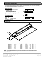
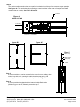
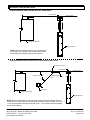
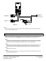
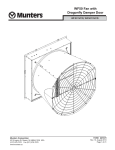
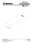
AEROTECH
CURTAIN MACHINES
BA4000 Series
R
R
Ventilation Systems
Munters Corporation
4215 Legion Dr. Mason, MI 48854-1036 USA
(517) 676-7070 Fax (517) 676-7078
www.munters.us/aerotech
FORM: QM1158
Rev. 3, October 2009
Page 1 of 20
USER'S MANUAL and INSTALLATION GUIDE
TABLE OF CONTENTS
Section
Page
Unpacking the Curtain Machine................................................................................................3
Demensions..............................................................................................................................3
Typical Mounting Configurations...............................................................................................4
Installation Instructions............................................................................................................ 5-8
External Cabling Methods...................................................................................................... 9-10
Electrical Wiring..................................................................................................................... 11-12
Operation..................................................................................................................................13
Maintenance.............................................................................................................................14
Troubleshooting..................................................................................................................... 15-17
BA4xxx Exploded View and Replacement Parts................................................................... 18-20
Thank You
Thank you for purchasing an Aerotech Curtain Machine. Aerotech equipment is designed to be
the highest performing, highest quality equipment you can buy. With the proper installation and
maintenance, it will provide many years of service.
PLEASE NOTE
To achieve maximum performance and insure long life from your Curtain Machine, it is essential that it be
installed and maintained properly. Please read all instructions carefully before beginning installation.
WARRANTY
For Warranty claims information see the "Warranty Claims and Return Policy" form QM1021
available from the Aerotech Ventilation System, Munters Corporation office at 1-800-227-2376
or by e-mail at [email protected].
Conditions and Limitations:
• Products and Systems involved in a warranty claim under the “Warranty Claims and Return
Policy” shall have been properly installed, maintained and operated under competent
supervision, according to the instructions provided by Aerotech Ventilation Systems,
Munters Corporation.
• Malfunction or failure resulting from misuse, abuse, negligence, alteration, accident or lack
of proper installation or maintenance shall not be considered a defect under the Warranty.
Munters Corporation
4215 Legion Dr. Mason, MI 48854-1036 USA
(517) 676-7070 Fax (517) 676-7078
www.munters.us/aerotech
FORM: QM1158
Rev. 3, October 2009
Page 2 of 20
UNPACKING THE EQUIPMENT
Before beginning installation, check the overall condition of the equipment. Remove packing materials, and
examine all components for signs of shipping damage. Any shipping damage is the customer's responsibility
and should be reported immediately to your freight carrier.
Each crate includes:
1-Curtain Machine with internal brake
1-Hardware Package
HP1065 for Curtain Machine
[A]
[A].....4 - 3/8" x 3.5" Hex Head Lag Screw ZP
[B].....4 - 3/8" Flat Washer ZP
Actuator Specifications
Power: 110 - 120 VAC
Amps: 1.0
Phase: 1
Frequency: 60 Hz
Load capacity: 4000 lbs.
[B]
DIMENSIONS
Model
BA4xx2-03
BA4xx2-30
BA4xx3-30
BA4xx4-30
BA4xx6-30
Travel Length
25.5"
25.5"
37.5"
49.5"
73.5"
Drive Speed
3 rpm
30 rpm
30 rpm
30 rpm
30 rpm
Lift Rate
3/4"/min.
71/2"/min.
71/2"/min.
71/2"/min.
71/2"/min.
A
58"
58"
70"
82"
106"
B
101/4"
101/4"
101/4"
101/4"
101/4"
C
6"
6"
6"
6"
6"
NOTE: These actuators are designed to open or close Aero-baffle, Aerotech modular-inlets or curtains
accordingly from signals received from any one of Aerotech's Air-Monitor Controls or Environmental
Computer Controls.
Munters Corporation
4215 Legion Dr. Mason, MI 48854-1036 USA
(517) 676-7070 Fax (517) 676-7078
www.munters.us/aerotech
FORM: QM1158
Rev. 3, October 2009
Page 3 of 20
TYPICAL MOUNTING CONFIGURATIONS
Figure 1
CEILING MOUNT
2 x Mounting
Boards
SIDE VIEW
Ceiling
Curtain Machine
Wall
Leave sufficient distance to
complete all necessary cabling
Model
BA4xx2
BA4xx3
BA4xx4
BA4xx6
A
34.125"
46.125"
58.125"
82.125"
A
Aerotech Ventilation Systems, Munters Corporation
Mason, MI 48854 USA www.munters.us/aerotech
LB2306
Wall
Curtain Machine
Leave sufficient distance to
complete all necessary cabling
2 x Mounting Boards
LOOKING UP FROM FLOOR
Figure 2
WALL MOUNT
Leave sufficient distance to
complete all necessary cabling
Ceiling
Aerotech Ventilation Systems, Munters Corporation
Mason, MI 48854 USA www.munters.us/aerotech
Curtain Machine
2 x Mounting
Boards
A
2 x Mounting Boards
LB2306
Wall
Leave sufficient distance to
complete all necessary cabling
Ceiling
Curtain Machine
SIDE VIEW
Munters Corporation
4215 Legion Dr. Mason, MI 48854-1036 USA
(517) 676-7070 Fax (517) 676-7078
www.munters.us/aerotech
FRONT VIEW
FORM: QM1158
Rev. 3, October 2009
Page 4 of 20
INSTALLATION INSTRUCTIONS
!
WARNING
!
WARNING
The location for the curtain machine must be structured strong enough to
withstand a 4000 lb. load. The wire rope cable used as a drive cable must also
have a minimum capacity of 4000 lbs.
High Voltage,
disconnect power
before installation.
Step 1
Install the curtain machine in the location specified on your ventilation system drawing. Using (4) 3⁄8" x
3.5" Hex Head Lag Screws and (4) 3⁄8" washers supplied in the hardware pack. For Typical Mounting
Configurations: See Figures 1 and 2, page 4.
Step 2
If the curtain machine will be operating Aero-Baffle or Modular Inlets, install baffle and inlets according to
their installation instructions. Install the curtains according to their installation instructions.
Step 3
Cable may be routed into the curtain machine through the slots provided on each side of the unit or through
(2) knock outs on the top of the unit. See Figure 3A and 3B.
knock out
Figure 3A
END VIEW
Figure 3B
Slot for Pulleys
SIDE VIEW
Munters Corporation
4215 Legion Dr. Mason, MI 48854-1036 USA
(517) 676-7070 Fax (517) 676-7078
www.munters.us/aerotech
FORM: QM1158
Rev. 3, October 2009
Page 5 of 20
Step 4
The curtain machine needs to have an equal load on both sides of the pull bar to assure proper operation.
See Figure 4A. This can be done by mounting the curtain machine in the center of run(s) of Aero-baffle,
modular inlets or curtains, See Figure 4B and 4C.
Pull Bar
Figure 4A
Cable Out End
*Load Side 1
*Load Side 2
*Load Side 1 = Load Side 2
Figure 4B
Figure 4C
Figure 5
Cable Clamp
Cable Thimble
Strap Pulley
Looped
Cable
Step 5
If curtain machine can not be mounted in the center for even loading, then
make a loop with cable, running the cable through a strap pulley, and
attaching the ends of cable to each side of pull bar. See Figure 5.
Step 6
If curtain machine is equipped with the Internal Double-Back option
(BA4xxx-D) go to step 8, otherwise proceed to step 7.
Munters Corporation
4215 Legion Dr. Mason, MI 48854-1036 USA
(517) 676-7070 Fax (517) 676-7078
www.munters.us/aerotech
FORM: QM1158
Rev. 3, October 2009
Page 6 of 20
Step 7A
Route the left drive cable down
the inside of the curtain machine
to the right side of pin #1. Route
the right drive cable to the left
side of pin #2. Wrap the drive
cables around the corresponding
pin to form a loop. Using (2)
cable clamps, attach (1) cable
clamp 21/2" from the top of the
pin and (1) cable clamp 1" above
the first cable clamp. Leaving a
minimum of 1" of cable at the
end of each loop (clamps not
provided.) See Figure 6A and
6B. Follow this step for each
drive cable.
Figure 6A
Figure 6B
CABLE OUT END
CABLE OUT EACH SIDE
Pin #1
Pin #2
Step 7B
Alternative cable routing shown
in Figure 6C and 6D.
Pin #1
Pin #2
Figure 6C
CABLE OUT LEFT SIDE
Munters Corporation
4215 Legion Dr. Mason, MI 48854-1036 USA
(517) 676-7070 Fax (517) 676-7078
www.munters.us/aerotech
Figure 6D
CABLE OUT RIGHT SIDE
FORM: QM1158
Rev. 3, October 2009
Page 7 of 20
Step 8A
If optional internal double-back was purchased, route the left
drive cable down the inside of the curtain machine of the right
side of pulley #1. Route the right drive cable to the left side of pulley #2. Wrap the drive cables around the bottom of its
corresponding pulley, and take each drive cable to the upper
bulkhead and through its corresponding hole. Using (2) cable
clamps, attach (1) cable clamp 1" from the cable end and (1)
cable clamp below, but as close as possible to the first cable
clamp. See Figure 7A. Refer to Steps 4-7 for cable routing
options.
Pulley #1
Pulley #2
Figure 7A
DOUBLE BACK
Step 8B
If adding the optional internal double-back kit (AC1950), in the
field, remove the 2 non-greaseable pins from the cable puller
bracket. Then, install the 2 greaseable pins, pulleys and hairpin
cotters. See Figure 7B.
Greaseable Clevis Pin
Remove pins that were in this location
3.5" Diameter pulley
with bearing
Cable puller
bracket
Hairpin cotter
Figure 7B
Munters Corporation
4215 Legion Dr. Mason, MI 48854-1036 USA
(517) 676-7070 Fax (517) 676-7078
www.munters.us/aerotech
FORM: QM1158
Rev. 3, October 2009
Page 8 of 20
EXTERNAL CABLING METHODS
CURTAIN Machine and Cabling without Hand Winch
Fixed Pulleys
Aerotech Ventilation Systems, Munters Corporation
Mason, MI 48854 USA www.munters.us/aerotech
LB2306
To Other Inlets
Curtain or Wall Inlets
Curtain Machine
NOTE: When the curtain machine is connected directly
to the inlets, they will both travel the same rate and the
normal load will be applied to the curtain machine.
CURTAIN Machine and Cabling with Hand Winch Installed
Double Free Pulleys
Fixed Pulleys
Fixed Attachment
Point
Aerotech Ventilation Systems, Munters Corporation
Mason, MI 48854 USA www.munters.us/aerotech
LB2306
Maximum 45° Angle
To Other Inlets
Hand Winch
Curtain or Wall Inlets
Curtain Machine
NOTE: When a Hand Winch is connected to the inlets and two free pulleys are connected in line, the inlets will travel at the same rate as the curtain machine. For every
1" the curtain machine travels the inlets will move 1". The normal load will be applied
to the curtain machine.
Munters Corporation
4215 Legion Dr. Mason, MI 48854-1036 USA
(517) 676-7070 Fax (517) 676-7078
www.munters.us/aerotech
FORM: QM1158
Rev. 3, October 2009
Page 9 of 20
Curtain Machine and Cabling with Hand Winch Installed
Free Pulley
Fixed Pulleys
To Other Inlets
Aerotech Ventilation Systems, Munters Corporation
Mason, MI 48854 USA www.munters.us/aerotech
LB2306
Maximum 45° Angle
Hand Winch
Curtain or Wall Inlets
Curtain Machine
NOTE: When a Hand Winch is connected to the inlets and a
Free Pulley is connected to the curtain machine, the baffle will
travel at twice the rate of the curtain machine. This is because
for every 1" the curtain machine travels the inlets will move
2". Twice as much load will be applied to the curtain machine
therefore, it will have half the pulling capacity.
Curtain Machine and Cabling with Hand Winch Installed
Free Pulley
Fixed Pulleys
To Other Inlets
Aerotech Ventilation Systems, Munters Corporation
Mason, MI 48854 USA www.munters.us/aerotech
LB2306
Maximum 45° Angle
Hand Winch
Curtain or Wall Inlets
Curtain Machine
NOTE: When a Hand Winch is connected to the curtain machine and a free
pulley is connected to the inlets, the inlets will travel at half the rate of the
curtain machine. This is because for every 1" the curtain machine travels, the
inlets will move 1/2". Only half of the load will be applied to the curtain machine
therefore it will have twice the pulling capacity.
Munters Corporation
4215 Legion Dr. Mason, MI 48854-1036 USA
(517) 676-7070 Fax (517) 676-7078
www.munters.us/aerotech
FORM: QM1158
Rev. 3, October 2009
Page 10 of 20
ELECTRICAL WIRING
Step 1
All wiring should be in accordance with National, State and Local electrical codes. Make electrical
connections as shown on terminal block label inside actuator. See Figure 8. Open, Close and Neutral
outputs from the Air-Monitor Control are to be wired to the Open (brown), Close (black) and Neutral (white)
inputs of the curtain machine. See Figure 8.
Step 2
If curtain machine is equipped with the Potentiometer Feed Back option (BA4xxx-P), connect the inlet
position output from the curtain machine to an environmental computer control having inlet capability. See
Figure 9. Control requires 5kΩ as maximum input.
-
To Internal
Potentiometer
Figure 8
BA4000/BA4500
+
Red
Ground Lug
in actuator
Internal Wires
Green
¬
Black
Black
White Pull Wires
to Control
Red
Figure 9
120 VAC
Signal Input
Step 3
If curtain machine is equipped with the Fan Limit Switch
option (BA4xxx-F), See Figure 10. Limit switch is rated for
1/3 HP or 11 Amps maximum load. If load is less than rating
proceed to Step 4, otherwise proceed to step 6.
Step 4
If the limit switch is to turn off the fan when inlets or curtains
open, and turn on when curtains close, wire one leg of fan
power to terminal marked 'COM' and connect fan wire to the
'NO' contact marked terminal 'A'. See Figure 11.
Figure 10
FAN LIMIT SWITCH
Fan Limit Switch
A
COM
120 or 240 VAC
Power Out to Fan
120 or 240 VAC
Fan Power Supply
Figure 11
Munters Corporation
4215 Legion Dr. Mason, MI 48854-1036 USA
(517) 676-7070 Fax (517) 676-7078
www.munters.us/aerotech
FORM: QM1158
Rev. 3, October 2009
Page 11 of 20
Step 5
If the limit switch is to turn on the fan when inlets or curtains open, and turn off when curtains close, wire
one leg of fan power to terminal marked 'COM' and connect fan wire to the 'NC' contact marked terminal
'B'. See Figure 12.
Fan Limit Switch
B
COM
120 or 240 VAC Power
Out to Fan
120 or 240 VAC Fan
Power Supply
Figure 12
Step 6
When the fan load exceeds the rating of the limit switch, an external load carrying relay (Aerotech SH4120
series) must be used in conjunction with the limit switch. If the load (fan) is to turn off when inlets or cur tains open and turn on when inlets or curtains close, wire limit switch and relay as shown in Figure 13. If
the load (fan) is to turn on when inlets or curtains open and turn off when inlets or curtains close, wire limit
switch and relay as shown in Figure 14, on page 13.
120 VAC Control
Signal from Controller or Relay Coil
Power Supply
120 or 240 VAC Fan
Power Supply
120 or 240 VAC Power
Out to Fan
A
COM
Figure 13
Munters Corporation
4215 Legion Dr. Mason, MI 48854-1036 USA
(517) 676-7070 Fax (517) 676-7078
www.munters.us/aerotech
Fan Limit Switch
FORM: QM1158
Rev. 3, October 2009
Page 12 of 20
120 VAC Control
Signal from
Controller or Relay
Coil Power Supply
120 or 240 VAC Fan
Power Supply
B
120 or 240 VAC Power
Out to Fan
Figure 14
Fan Limit Switch
Step 7
Turn on the electrical supply to the curtain machine and the Air-Monitor Control or environmental computer
control. Proceed to Operation Section.
Operation
NOTE: The curtain machine is shipped from the factory with the open and close limit adjustment clamps set
for mid range operation. These clamps MUST be set for your installation to assure proper operation.
Step 1
To adjust the close limit switch, manually run curtain machine to the full close position for the curtains or
inlets. Position the close limit adjustment clamp against pull bar so that it activates the close limit switch.
Manually run curtain machine partially open and back close to check for proper position.
Step 2
To adjust the open limit switch, manually run the curtain machine to the full open position for the curtains
or inlets. Position the open limit adjustment clamp against pull bar so that it activates the open limit
switch. Manually run the curtain machine partially close and back open to check for proper position of
clamp.
Readjust clamp as necessary.
Step 3
Place all switches and controls in auto. Test operation of curtain machine using the Air-Monitor control or
environmental computer control.
Munters Corporation
4215 Legion Dr. Mason, MI 48854-1036 USA
(517) 676-7070 Fax (517) 676-7078
www.munters.us/aerotech
FORM: QM1158
Rev. 3, October 2009
Page 13 of 20
MAINTENANCE
!
WARNING
High Voltage,
disconnect power
before servicing.
!
WARNING
Moving parts,
disconnect power
before servicing.
!
WARNING
Do not power wash
electrical devices.
1)Remove dust buildup from Curtain Machine: using a soft brush or dry cloth. Never use liquids to
clean electrical cords or wires.
2)Grease Ball Screws and Check Pulleys: A high quality Lithium based grease should be applied
to the ball screw and pulleys every 6 months depending on the frequency of operation. Also, check to make
sure that the pulleys will turn freely.
3)check CABLES: Confirm that all cables are in good condition and are properly positioned in the groove of
the pulleys. Check this regularly to avoid damage to the building or equipment. Check any clamps being
used to verify they are secure.
4)check LIMIT CLAMPS: Verify that the limit clamps are adjusted to allow the air inlet to open and close
within the inlets operating range. This should be performed every 6 months.
5)check ELECTRICAL CONNECTIONS: With the power turned off to the unit, verify that the termination
points are secure and all wires are in good condition. This should be done yearly.
6) Check GEARMOTOR AND BRAKE: No lubrication or adjustment is needed on the gearmotor/brake
assembly. Some maintenance may be necessary for reliable operation if the unit will sit idle for an extended
period of time. If the unit will sit idle for more than one month, the following steps should be performed
before the actuator is put back into service.
STEP 1-Apply power to the actuator in the open and then the close direction.
STEP 2-Verify that the gearmotor will operate in both directions.
STEP 3-If the unit will not operate, it may be necessary to “break loose” the gearmotor brake. Turn power
off to the unit. Using a pair of pliers or vise grips, turn the brake hex nut 1/4 of a turn. On some
units the hex nut may not be visible. If the hex nut is not visible, turn the gearmotor shaft where it
extends through the brake 1/4 of a turn.
STEP 4 -Perform steps #1 and #2 again. If the unit will still not operate, refer to the troubleshooting
procedures for further instructions.
Munters Corporation
4215 Legion Dr. Mason, MI 48854-1036 USA
(517) 676-7070 Fax (517) 676-7078
www.munters.us/aerotech
FORM: QM1158
Rev. 3, October 2009
Page 14 of 20
TROUBLESHOOTING
!
WARNING
Moving parts,
disconnect power
before servicing.
SYMPTOM
Curtain Machine
will not close
Curtain Machine
will not open
!
WARNING
High Voltage,
disconnect power
before servicing.
!
WARNING
Moving parts,
disconnect power
before servicing.
POSSIBLE CAUSE
CORRECTIVE ACTION
1.Close limit switch is activated.
1. Run Curtain Machine off the Close limit.
2.No 120 VAC at the close input.
2. Check for voltage from the Air-Monitor
Control.
3.Brake has not released.
3. Turn Curtain Machine off and listen at
brake for click when turning machine on. If
120 VAC is on wires #7 & #8, brake is
bad. Follow maintenance instruction #6. If
problem still occurs replace brake.
4.Bad circuit board.
4. Check for 120 VAC on wires #9 and #10.
1.Open Limit Switch is activated.
1. Run curtain Machine off the Open Limit.
OTHER SYMPTOMS:
If a BA4xxx Series Actuator will not operate, some testing can be performed to determine the cause of the
problem. A voltmeter capable of measuring 120VAC will be needed to test the unit thoroughly. To troubleshoot,
power must be on. Use EXTREME CAUTION when checking voltage. DO NOT attempt these tests if you are not
experienced in working on electrical control systems, instead contact a qualified electrician or service technician.
Refer to the wiring diagram on page 15 when performing these tests. It is recommended to perform all of the steps
listed below in the event that more than one problem is present.
STEP 1: Verify that 120VAC is present at the input terminal block on the circuit board in the actuator. If no voltage is
present, the problem is not with the actuator and further testing of the wiring to the actuator should be done. If voltage is present, proceed to Step #2.
STEP 2: Confirm that the limit switch portion of the actuator circuit board is functioning properly. With a close signal
present on the input to the board, verify that there is 120VAC between wire #1 and Neutral (N). Change the input
signal from a close to an open signal and test for 120VAC between wire #4 and N. If no voltage is present at either
of these points, replace the circuit board.
STEP 3: Check the operation of the open and close limit switches. With a close signal to the board, test for voltage
between Neutral and #3. If no voltage is present, one of the close limit switches is defective or is in the activated
position. With an open signal present, test between wire # 6 and N. If no voltage is present, one of the open limit
switches is defective or is in the activated position.
Munters Corporation
4215 Legion Dr. Mason, MI 48854-1036 USA
(517) 676-7070 Fax (517) 676-7078
www.munters.us/aerotech
FORM: QM1158
Rev. 3, October 2009
Page 15 of 20
STEP 4: Confirm that the remaining areas of the actuator circuit board are functioning properly. With a close signal
present on the input to the board, verify that there is 120VAC on the following points. Test between wires #7 and
#8, #9 and #10, N and #13. Change the input signal from a close to an open signal and test for 120VAC at the
following points. Test between wires #7 and #8, #9 and #11, N and #12. If no voltage is present at any of these
points, replace the circuit board.
STEP 5: Check the operation of the brake with either a close or an open signal to the unit. It should be possible to
turn the brake hex nut freely by hand at this time. If the hex nut is not visible, the shaft extending through the center
of the brake should turn freely. If it will not turn freely, the gearmotor brake (Cat. No. AC1934) should be replaced.
STEP 6: The gearmotor should be tested without the brake installed at this time. The air inlet will fall open when
the brake is removed from the gearmotor. The hand winch should be adjusted to open the air inlet to remove the
load from the actuator.
If the brake hex nut is visible it will need to be removed. The hex nut is secured to the motor shaft with two set
screws. It will be necessary to loosen both of these set screws so that the hex nut can then be slid off of the shaft.
If the hex nut is located between the motor and brake, the brake must be removed rather than the hex nut.
The brake is secured to the motor with two or four machine screws. Remove these screws and take the brake
off of the motor. Supply a close and an open input signal to the actuator and verify that the gearmotor will operate
in both directions. If the motor will not operate in either of these directions, the gearmotor will need to be replaced.
If the gearmotor will run in one but not the other direction, the gearmotor is working, but one of the components
discussed in the previous steps is not functioning.
If a replacement gearmotor is required, the
AC1934 brake will not need to be ordered as it
will be included with the new gearmotor. If the
catalog number for the BA4xxx Series Actuator
being serviced ends in a -03, the AC1607
gearmotor/brake assembly should be ordered.
If the catalog number ends in -30, the AC1606
gearmotor/brake assembly should be ordered.
120 VAC
Signal Input
Internal Wires
Ground Lug
in actuator
BA4000
Munters Corporation
4215 Legion Dr. Mason, MI 48854-1036 USA
(517) 676-7070 Fax (517) 676-7078
www.munters.us/aerotech
FORM: QM1158
Rev. 3, October 2009
Page 16 of 20
Munters Corporation
4215 Legion Dr. Mason, MI 48854-1036 USA
(517) 676-7070 Fax (517) 676-7078
www.munters.us/aerotech
CIRCUIT BOARD
120 VAC
TROUBLESHOOTING CONTINUED
AEROTECH
A MUNTERS COMPANY
MASON, MI
CATALOG NO. AC6939
120 VAC SIGNAL INPUT
CAPACITOR
250 VAC
12.5 F
OPEN LIMIT
SWITCHES
CLOSE LIMIT
SWITCHES
NOTE: WIRES #7, #8, #9, #10 AND #11 ARE
WIRES FROM THE MOTOR AND BRAKE.
BRAKE
MOTOR
FORM: QM1158
Rev. 3, September 2009
Page 17 of 20
Munters Corporation
4215 Legion Dr. Mason, MI 48854-1036 USA
(517) 676-7070 Fax (517) 676-7078
www.munters.us/aerotech
Double Back Option
FORM: QM1158
Rev. 3, September 2009
Page 18 of 20
Potentiometer Feedback
Option
Fan Limit Switch Option
Ref.
No.
1
2
3
4
5
6
7
8
9
10
11
12
13
14
15
16
17
18
19
20
21
22
23
24
25
26
27
28
29
30
31
32
33
34
Cat. No.
AC1955
AC1956
AC1957
AC1959
AC1941
KP1052
KX1455
AC1937
AC1914
KE1154
AC1939
AC1962
AC1608
AC2503
AC1903
AC1905
KW4150
AC1601
AC1602
AC1616
AC1904
AC1607
AC1606
AC1934
KP1108
KP1252
KW3023
KX1255
AC1901
KN1951
AC1915
AC1910
AC1902
AC1948
AC1486
AC1487
AC1488
AC1489
AC1909
AC1922
AC1923
AC1924
AC1926
AC1908
AC1943
Description
Bar, limit switch activation, BA4xx2
Bar, limit switch activation, BA4xx3
Bar, limit switch activation, BA4xx4
Bar, limit switch activation, BA4xx5
Clamp, limit adjustment
Cotter Pin
Spring, Compression
Retainer, Limit Switch Spring
Bracket, Open/Close Switch
Connector, moisture resistant 14-22 AWG
Circuit Board
Switch, micro
Capacitor, 12.5 mfd for BA4000 only
Capacitor, 12.5 mfd for BA4500 only
Bulkhead, middle
Bearing, thrust, 3-bolt flange, 1"I.D.
Washer, flat, zinc plated
Coupler body, 1" bore, 095
Spider Insert, for 090/095, rubber
Coupler body, 1/2" Bore, 095
Bulkhead, lower
Gearmotor with brake, 3 rpm
Gearmotor with brake, 30 rpm
Brakes for AC1606/AC1607, round
Cotter Hairpin, 1/8"D x 2.5"L
Clevis pin, non-greaseable
Flat washer, nylon
Spacer, nylon
Cable puller
Locknut for ballnut
Guide block, on cable puller, plastic
Chassis Cap, bottom end
Bulkhead, upper
Bearing, 2 bolt flange, 1"I.D.
Ball Screw Assembly, BA4xx2
Ball Screw Assembly, BA4xx3
Ball Screw Assembly, BA4xx4
Ball Screw Assembly, BA4xx6
Chassis Cap, top end
Chassis, BA4xx2
Chassis, BA4xx3
Chassis, BA4xx4
Chassis, BA4xx6
Bracket Pulley Cover
Pulley, with bearing
Munters Corporation
4215 Legion Dr. Mason, MI 48854-1036 USA
(517) 676-7070 Fax (517) 676-7078
www.munters.us/aerotech
Qty.
1
1
1
1
2
2
2
2
1
11
1
4
1
1
1
1
1
1
1
1
1
1
1
1
2
2
2
2
1
1
3
1
1
1
1
1
1
1
1
1
1
1
1
1
3
FORM: QM1158
Rev. 3, October 2009
Page 19 of 20
Ref. No.
Cat No.
Description
Qty.
35
AC1961
Spindle for 3.5" Pulley
3
36
AC1907
Bracket, Pulley Base
1
37
AC1916
Pull Retainer, BA4xx2
1
AC1917
Pull Retainer, BA4xx3
1
AC1918
Pull Retainer, BA4xx4
1
AC1920
Pull Retainer, BA4xx6
1
38
AC1928
Cover, BA4xx2, w/ hinges/latch
1
AC1929
Cover, BA4xx3, w/ hinges/latch
1
AC1930
Cover, BA4xx4, w/ hinges/latch
1
AC1932
Cover, BA4xx6, w/ hinges/latch
1
39
AC1947
Hinge, cane bolt, RH
1
40
KX1041
Latch, Slide bar assembly, SS
Varies
41
KX1042
Latch, Lock bushing, ZP
1
42
AC1933
Hinge, cane bolt, LH, ZP
Double Back Option
43
AC1943
Pulley, with bearing
2
44
KP1253
Clevis pin, greaseable
2
Potentiometer Feedback Option
45
AC1425
Potentiometer kit, 5kΩ w/ bracket and cable
1 included in AC1425
46
FC1205
3 Pole terminal block, 16AWG max.
1
Fan Limit Switch Option
47
KX1454
Spring, Tension
1
48
KP1106
Hairpin, Cotter
1
49
AC1911
Bar, Fan Limit Activation
1
50
KW3022
Flat Washer, nylon
1
51
KP1254
Clevis Pin
1
52
AC2501
Bracket, Fan switch
1
53
AC1962
Switch, micro
1
Munters Corporation
4215 Legion Dr. Mason, MI 48854-1036 USA
(517) 676-7070 Fax (517) 676-7078
www.munters.us/aerotech
FORM: QM1158
Rev. 3, October 2009
Page 20 of 20