1
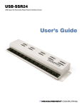
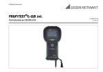
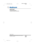
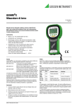
CONFIDENTIAL ULTIMO Module / MLB/MPA Series Instruction Manual Ver.1.17En01 ULTIMO Module For MLB/MPA series Instruction Manual JMMC-11023 Ver. 1.17En01 Apr. 16th, 2014 JM Energy Corporation JM Energy Corporation 1 CONFIDENTIAL ULTIMO Module / MLB/MPA Series Instruction Manual Ver.1.17En01 SAFETY PRECAUTIONS ◆The following marks indicate notes you should pay attention to in this documentation. Please read these notes and understand their contents before using the product. ◆Even if the power supply is not connected to the module, cell always has voltage and electric energy. Please construct arrangement and wiring, and check by a person who has qualification and knowledge. ■ This User’s Manual uses the following marks to explain safety precautions. Misuse of the product “would very likely result in death or Danger Warning Caution serious injury.” Misuse of the product “might result in death or serious injury.” Misuse of this product “might result in injury or property damage.” ■ The following marks indicate rules for you to observe. This indicates a “prohibited” action. This indicates a “must” action. About this User’s Manual 1. No part or whole of this Manual may be reprinted without approval. 2. Contents of this Manual may be changed without notice. 3. Every effort was made to ensure the accuracy of the contents of this Manual. Should you have any questions, or notice inaccuracies or omissions, please contact us. 4. The contents of this documentation do not intend to give approval to industrial properties and any other rights. Therefore it is not guaranteed that the contents do not infringe on third party's right. 5. JM Energy is not responsible for anything that occurs due to actions contrary to the instructions of this Manual. 6. After reading this Manual, please keep it in a safe place and have it with you for reference whenever you use the product. JM Energy Corporation 2 CONFIDENTIAL ULTIMO Module / MLB/MPA Series Instruction Manual Ver.1.17En01 Danger Do not disassemble, or alter the ULTIMO module. The cover must be firmly fixed with screws when in use. ● Doing so may result in electric shock, injury, smoke, explosion, or ignition. Do not heat the module or expose it to open flame ● Doing so may result in smoke, explosion, or ignition. Wear a protective gear such as insulated gloves when handling the conductive terminals. ● Failure to do so may result in electric shock, burn, or injury. JM Energy Corporation 3 CONFIDENTIAL ULTIMO Module / MLB/MPA Series Instruction Manual Ver.1.17En01 Warning Do not short-circuit the terminals. ● Short circuit may result in electric shock, burn, or injury, and may also lead to a unit breakdown with liquid leakage, heat, smoke, explosion, or ignition. ● Pay special attention to short-circuiting when using a metal tool. Do not subject ULTIMOTM to excessive shock or vibration. ● Doing so may result in internal short-circuiting, liquid leakage, and unit breakdown. Do not put ULTIMO module on an electromagnetic cooking device, or in a microwave oven or a high-pressure container. ● Doing so may result in liquid leakage, explosion, or unit breakdown. Do not use the product outside the range of its voltage and current specification. ● Using the product at a voltage and current outside the specification may shorten its life, and may lead to liquid leakage, heat, smoke, explosion, or ignition. If liquid leakage, odor, smoke, deformation, gas release valve actuation or other abnormal situations occur, stop using the product immediately. ● Damage to the unit may result in heat, smoke, ignition, electric shock or injury. Should leaking liquid enter your eyes, do not rub your eyes. Rinse them well with tap water (clean water) and seek immediate medical attention. Should you swallow the contents, rinse your mouth with water, and seek immediate medical attention.. JM Energy Corporation 4 CONFIDENTIAL ULTIMO Module / MLB/MPA Series Instruction Manual Ver.1.17En01 Caution ULTIMOTM has polarity (positive and negative). Use the correct polarity ● Incorrect use of polarity may result in liquid leakage, heat, smoke, explosion, or ignition. Should leaking liquid stains the clothes, rinse it away immediately with tap water (clean water). Upon receiving your product, please make sure there is no deformation, liquid leakage, odd odor, heat, or any other abnormal condition. Should you find any abnormal condition upon receiving the product, please do not use it. Contact us immediately. About Transportation Do not subject ULTIMO module to excessive shock or vibration during transit. Do not do excessive accumulation of the packing box. Do not expose the module to: rainwater, ocean water, snow ice, condensation, or freezing conditions. The voltage of the ULTIMO Module must be maintained in its specified operating range. JM Energy Corporation 5 CONFIDENTIAL ULTIMO Module / MLB/MPA Series Instruction Manual Ver.1.17En01 Index SAFETY PRECAUTION 1. Summary - - - - - - - - - - - - - - - - - - - - - - - - - - - - - - - - - - - - - - - - - - - - - - - - - - - - - -7 2. Appearance - - - - - - - - - - - - - - - - - - - - - - - - - - - - - - - - - - - - - - - - - - - - - - - - - - - - -7 3. Module installation requirements - - - - - - - - - - - - - - - - - - - - - - - - - - - - - - - - - - - - - - 8 4.Moving and transport directions -- - - - - - - - - - - - - - - - - - - - - - - - - - - - - - - - - - - - - - -9 5. Storage directions - - - - - - - - - - - - - - - - - - - - - - - - - - - - - - - - - - - - - - - - - - - - - - - - -9 6. Configuration diagram of charge and discharge system- - - - - - - - - - - - - - - - - - - - - - - 10 7. Module fixation 7.1 MLB Series - - - - - - - - - - - - - - - - - - - - - - - - - - - - - - - - - - - - - - - - - - - - - - - - -11 7.2 MPA Series - - - - - - - - - - - - - - - - - - - - - - - - - - - - - - - - - - - - - - - - - - - - - - - - -11 8. Connection between modules 8.1 Power line Circuit - - - - - - - - - - - - - - - - - - - - - - - - - - - - - - - - - - - - - - - - - - - - -12 8.2 Control Circuit (Input/Output signals)- - - - - - - - - - - - - - - - - - - - - - - - - - - - - - - -14 8.2.1 Variation of Module Connections- - - - - - - - - - - - - - - - - - - - - - - - - - - - - - -14 8.2.2 Connectors and cables - - - - - - - - - - - - - - - - - - - - - - - - - - - - - - - - - - - - - -15 8.2.3 Input and Output Signals - - - - - - - - - - - - - - - - - - - - - - - - - - - - - - - - - - - -18 9. DIP SW Setting - - - - - - - - - - - - - - - - - - - - - - - - - - - - - - - - - - - - - - - - - - - - - - - - - 19 10.Simple Master mode- - - - - - - - - - - - - - - - - - - - - - - - - - - - - - - - - - - - - - - - - - - - - - 22 11. Precautions for use- - - - - - - - - - - - - - - - - - - - - - - - - - - - - - - - - - - - - - - - - - - - - - - 23 12. Maintenance - - - - - - - - - - - - - - - - - - - - - - - - - - - - - - - - - - - - - - - - - - - - - - - - - - -25 13. In the case of failure- - - - - - - - - - - - - - - - - - - - - - - - - - - - - - - - - - - - - - - - - - - - - - 26 14. Dispose treatment-- - - - - - - - - - - - - - - - - - - - - - - - - - - - - - - - - - - - - - - - - - - - - - - 26 15. Product specifications- - - - - - - - - - - - - - - - - - - - - - - - - - - - - - - - - - - - - - - - - - - - - 27 16. Export - - - - - - - - - - - - - - - - - - - - - - - - - - - - - - - - - - - - - - - - - - - - - - - - - - -31 17. Contact us - - - - - - - - - - - - - - - - - - - - - - - - - - - - - - - - - - - - - - - - - - - - - - - - - - - - 31 JM Energy Corporation 6 CONFIDENTIAL ULTIMO Module / MLB/MPA Series Instruction Manual Ver.1.17En01 1. Summary This lithium-ion capacitor module (referred to as the module or the product herein after) has the voltage monitor function for each cell and has the function to adjust for balanced operation among cells. If the module detects any cell exceeding the upper/lower operating voltage limits, it sends out an excessive discharge or over-charging alarm signal, and indicates the need to control the discharge or charging. If any cell exceeds or does not meet the voltage range that is set in advance, FET switches are turned ON and a resistive discharge is performed to attain the voltage balance among cells and keep the voltage within the set limits. 2. Appearance (-) Negative Terminal (+) Positive Terminal (-) Negative Terminal (+) Positive Terminal MLB series (Laminate cell) MPA series (Prismatic cell) Fig.2-1 Appearance JM Energy Corporation 7 CONFIDENTIAL ULTIMO Module / MLB/MPA Series Instruction Manual Ver.1.17En01 3. Module installation requirements Please follow the notes below when installing the module. About the safety vent of cell The cell may catch fire or cause accident if the cell undergoes physical damage, overcharge, over discharge, or any abnormality. When such an accident happens, in order to control the abnormal condition to the minimum, the safety vent with which ULTIMO is equipped operates, and an electrolyte and gas are emitted around it. Please consider the surrounding ventilation and protection of surrounding apparatus. Do not use in or near flammable or combustible liquids or vapors An explosion or fire might be caused. Do not use it in in close contact with the combustible and flammable liquids such as alcohol and thinner or their vapors. Do not expose to temperatures outside the specified operating temperature range, heating apparatus or direct sun light Operating temperature range :- 30ºC to 70ºC Do not use in caustic or corrosive environments. These environments may cause corrosion inside the module which may lead to a malfunction or fire. Avoid direct contact with water and high humidity conditions Use only in the humidity range of: 90%Rh or less (non-condensing) Do not use if dew or condensation are present.. Avoid contact with salt water liquid or vapors Contact may result in metal corrosion. Do not use in locations with excessive dust. Dust may lead to an electric shock or fire. Do not place any large mass or weight on the module Placing large mass or weight may damage the module. Do not put the module on a tilted place or a vibrating place without fixation. The module may fall and break and it could cause injury Do not place the module in strong magnetic or electric fields. This may cause the module to malfunction. JM Energy Corporation 8 CONFIDENTIAL ULTIMO Module / MLB/MPA Series Instruction Manual Ver.1.17En01 4. Moving and transport directions Please follow to the notes below when moving or transporting the modules. Remove all cable connections to the module Moving without cables may cause damage to cables and modules, and injury by stumble. Do not carry the terminal block. It may cause injury by damage or the fall of product. Please keep the cover attached in proper position. There may be an electric shock or injury. Do not subject the module to excessive vibrations or impact while transportation. Regulations for Air Transport Currently, Lithium ion capacitor or its module is not classified as a hazardous material under the 2012 IATA regulation. However, air transport regulations may change. Before packing for air transport, check the latest transport regulations to ensure the correct means of packaging and transportation. 5. Storage directions Please follow to the notes below when keeping the module without using for a long term. Charge the module voltage to more than 3V per cell but less that 3.8V per cell. For example, a module with 6 cells should be charged to a voltage above 18V but less than 22.8V Set the module in the keeping mode by the dip switch and the reset switch inside of front panel to suppress power consumption. (Please refer to “DIP SW setting” of clause 9 for details.) Protect the terminal not to touch by mistake. Keep it in the place that is appropriate for clause 3 above after removing all the connected wirings. JM Energy Corporation 9 CONFIDENTIAL ULTIMO Module / MLB/MPA Series Instruction Manual Ver.1.17En01 6. Configuration Diagram of Charge and Discharge System The configuration example of the charge and discharge system using ULTIMO module of series-parallel connection is shown in Fig.6-1. The maximum module in-series number is 12 sets, and the maximum parallel number is 16 sets. Charge Switch Power Supply Discharge Switch + + - - Load Switch etc Protection circuit etc Module A or Module Group A Module B or Module Group B + + + Ultimo + Ultimo -- Module - - Module ・ ・ ・ ・ ・ ・ + + Ultimo - Module + + Ultimo - Module - Over charge alarm← Master controller ・・・・ - DC9~36V Master controller DC9~36V Over discharge alarm← Over temp alarm← Sleep request→ WakeUp request→ Fig. 6-1 Configuration Diagram of Charge and discharge system To protect the module in case of over-charge, over-discharge or abnormal temperature, use power supply or load which has a shutoff function or a switch to disconnect charge and discharge. (The module does not have a shutoff function.) When connecting a module or a module group in parallel, it is recommended to prepare a shutoff function such as breaker etc. which is adapted for working voltage and current. JM Energy Corporation 10 CONFIDENTIAL ULTIMO Module / MLB/MPA Series Instruction Manual Ver.1.17En01 7. Module fixation 7.1 MLB series In fixing a MLB series module, please fix certainly with M5 screw using a module attachment hole (4 places). 7.2 MPA series In fixing a MPA series module, please refer to the example of the following figure. The attachment size of a module fixed screw, please refer to “module outline view”. Please design metal fittings not to interfere with a screw head of module. Please use a 1.6-mm thickness spacer on the back surface of the metal fitting for this screw. Safety vent At the abnormalities, the safety vent of cell may operate as mentioned in "Module location requirements" of clause 3. In that case, electrolyte may spout. Please consider to design a protection cover etc. on the top side of the safety vent if needed. Metal fitting M4 Screw Recommended Installation direction Fig. 7-1 Fixation of MPA series JM Energy Corporation 11 CONFIDENTIAL ULTIMO Module / MLB/MPA Series Instruction Manual Ver.1.17En01 8. Connection between modules 8.1 Power line Circuit As shown in Fig.6-1 of clause 6, it is recommended to prepare a shutoff function such as breaker etc. to the module group. In case the shutoff function is not prepared, please make module in-series and parallel connection with the following procedure. Power Resistor To Power supply or Load P0 P-1 P-2 P-m Module A / Module group A Module B / Module group B Module M / Module group M + ULTIMO ++ ULTIMO + ULTIMO - Module A-n - Module - - B-n M-n ・ ・ ・ ・ ・ ・ A-2 ・ - M-2 - - Module + ULTIMO Module - B-1 + ULTIMO ・ + + ULTIMO Module A-1 ・ ・・・・ B-2 + ULTIMO Module - Module M-1 ++ ULTIMO + ULTIMO - -Module - Module N0 To Power Supply or Load N-1 N-2 N-m Fig. 8-1 Diagram of Series and parallel module connection 1. Connect modules in series Group A(A-1, A-2, ----, A-n), Group B(B-1, B-2, ----, B-n),-----, and Group M(M-1, M-2, ----, M-n) 2. Connect bottom (Minus) side of module groups in parallel N-1, N-2, ----, N-m 3. Connect upper (Plus) side of module groups in parallel. P-1, P-2, ----, P-m Notice: When connecting a module or a module group, and those voltage differences are large, big current may flow. When a module or a module group has a higher voltage difference, the following connection method is recommended. JM Energy Corporation 12 CONFIDENTIAL ULTIMO Module / MLB/MPA Series Instruction Manual Ver.1.17En01 1) Make temporary connection of a module or the module group by a power resistor with sufficient power capacity, etc., and arrange the module voltage. 2) After performing the content1), remove the resistor and make normal connection. 4. Connect the Minus (-) of Power supply or Load (N0) 5. Connect the Plus (+) of Power supply or Load (P0) Confirm there is no voltage difference among modules which are connected in series. Make connections only after confirming the charge/discharge switch (or, power supply and load) is turned off. Use protective equipments (insulation gloves and insulating mat, etc.) which are appropriate for the voltage. Connect the power supply and the load to the module with the most efficient way in order to minimize voltage drop by interconnection resistance. Choose electric wires which have enough current capacity for module connection. -If the electric wire is inapposite, there may be overheating, fire or a large voltage descent of the electric wire. The terminals and the cable shall be surely connected at the torque of 4 to 4.5Nm with M6 bolt. -A loose connection may generate heat, which could lead a fire. - Excessive torque may lead terminal damage. Operate the charge in accordance with the charger’s manual when you use a conventional charger. -Improper use may result in breakdown, liquid leakage, generation of heat, smoke, explosion, ignition, or damage Excessive current may flow backwards from a module to a charging apparatus in forming a circuit when voltage of the charging apparatus is lower than the module voltage. Connect the positive and the negative terminals correctly. Do not short-circuit the positive and negative terminals. JM Energy Corporation 13 CONFIDENTIAL ULTIMO Module / MLB/MPA Series Instruction Manual Ver.1.17En01 8.2 Control circuit (Input/Output signals) 8.2.1 Variation of module connections When connecting modules in series, it is necessary to connect a master controller. However, when the modules do not need to perform communication with a host and a series connection is 4 modules or less, “Simple master mode” without a master controller can perform balance between modules. For parallel connection of series strings of modules, please refer to ”Instruction Manual of a Master controller NA102.” 【Normal Connection in Series (with a master controller)】 Module 1 Module 2 Module n-1 Module n Master controller External Device (HOST) Fig. 8-2-1 Series Connection of modules with a Master Controller Set an ID number to each module. Refer to "DIP SW Setting" of clause 9. For details, please refer to the Instruction Manual of a Master controller. 【Master Controller less Connection in Series 】(4 modules or less) Module1 Module2 Module4 (Simple Master) Module3 External Device Fig. 8-2-2 Series Connection of modules easy without a Master Controller (Simple master mode) Set an ID number to each module and the Simple master mode needs to be set to a module. Please refer to "DIP SW Setting" of clause 9 JM Energy Corporation 14 CONFIDENTIAL ULTIMO Module / MLB/MPA Series Instruction Manual Ver.1.17En01 8.2.2 Connectors and cables [Connectors] MLB series Connector2 Connector1 Pin Assignment of connector1&2 MPA series ※This is the pin assignment is the front view of the Fig.8-2-3. Connector2 Connector1 Fig.8-2-3 Layout and Pin assignment of connectors There are two identical connectors (1&2) for inter-module connection. The connectors are used to communicate with modules next to each other, external device (simple master mode or stand alone), or a master controller as shown in Fig. 8-2-4. There is no priority of the connector 1 and 2. Module1 Module2 Module n-1 Cable2 Module n Cable2 Fig. 8-2-4 Module Connection Cable1 External device or master controller Table 8-1 Pin Assignment of Connector to External device or master controller@ Cable1 Connector Connector 1&2 Pin No. 1 2 3 4 5 6 7 8 9 10 11 12 13 14 15 to 18 19 20 Signal Name Signal direction Module External Remarks Over charge alarm Over charge alarm (G) Over discharge alarm Over discharge alarm (G) Over temp alarm Over temp alarm (G) Sleep command (+) Sleep command (-) WakeUP command (+) Anode of Photo Coupler Anode of Photo Coupler WakeUP command (-) (N.C) Do not connect (shield) Use only when connecting a shielded wire. This pin is connected only between connector 1 & 2, and not connected to the case. Attention Attention(G) (N.C) Do not connect RS485 A RS485 B JM Energy Corporation 15 CONFIDENTIAL ULTIMO Module / MLB/MPA Series Instruction Manual Ver.1.17En01 Table 8-2 Pin Assignment of Cable between modules @ Cable2 Module n Pin-No. 1 2 3 4 5 6 7 8 9 10 11 12 13 14 15 16 17 18 19 20 Module n-1 Signal Name Remarks Pin-No. 1 2 3 4 5 6 7 8 9 10 11 12 13 14 15 16 17 18 19 20 Over charge alarm Over charge alarm (G) Over discharge alarm Over discharge alarm (G) Over temp alarm Over temp alarm (G) Sleep command (+) Sleep command (-) WakeUP command (+) WakeUP command (-) (N.C) (shield) Attention Attention(G) (N.C) (N.C) (N.C) (N.C) RS485 A RS485 B [Cables] Cables which connect between modules and a module to external connection or a master controller should adjust length with the actual situation complying with the following contents. Please adjust L size according to actual situation. To Module or Master-controller To Module GT8E-20DS-HU GT8E-20DS-HU Note: For connection with an external device, please select the connectors which suit the external device. 1. Suitable cables should be chosen according to usage environment. Please use a twisted-pair cables and cables with shield according to usage environment. When using shielded cables, the shielded part should be evaluated sufficiently and should be processed appropriately. 2. Unused pins are for options. Please do not connect. 3. Type of Connector at Module-side: HIROSE GT8E-20DS-HU Please choose the contact which suits the wire rod. JM Energy Corporation 16 CONFIDENTIAL ULTIMO Module / MLB/MPA Series Instruction Manual Ver.1.17En01 [Notes for cable layout design] Please separate the signal cables from power lines in order to avoid interference of noise etc. Also when connecting the signal cables with an external device, please separate it from the power line cables which generates noises. Other power lines Signal line Separate Power lines and Signal lines. Do not band together. External Separate Power lines and Signal lines. Do not band together Device Twisted pair cable / shielded cable is recommended. Power lines Module Other power lines Separate Power lines and signal lines. Do not band together. External Master controller Signal line device Separate Power lines and signal lines. Do not band together. Module Power line Twisted pair cable / shielded cable is recommended. Please apply above notes to both MLB and MPA series. The unused signal lines shown in Table 8-1&8-2 should not be wired to avoid interference of noise. JM Energy Corporation 17 CONFIDENTIAL ULTIMO Module / MLB/MPA Series Instruction Manual Ver.1.17En01 8.2.3 Input and output Signals [Output Signals] Signal Name Table 8-3 List of Output signals Contents Over charge alarm Active when one of cells voltage exceeds the over-charge limit. Over discharge alarm Active when one of cells voltage exceeds the Over-discharge limit. Active when Cell temperature exceeds the upper or lower temp. limit. Note: Every output signal is “Low Active” Over temp alarm Since output signals of a module have circuits shown in the following figure, please prepare suitable control circuits externally. Please use a current limiting resistor appropriately upon use of relay, photo-coupler, or else. IC=100mA (max.) Relay or 36V(max) Photo-coupler Charge discharge side Use twisted pair as needed (Host) Output circuits of module Fig. 8-2-5 Control circuits of module output signals When an over charge alarm is active, please suspend charge or cut a charge line. When an over discharge alarm is active, please suspend discharge or cut a discharge line. When an over temp alarm is active, please suspend charge/discharge or cut a line of charge/discharge, and needs to reduce cell temperature. [Input Signals] Signal Name WakeUP command Table 8-4 List of Input signals Contents Start-up signal for controller Sleep command Shifts to Sleep mode signal for controller * Signals are “Low Active” * Input signal should be an edge, a pulse (100 msec or longer), or a voltage level. * If above signals are not inputted, the controller will be in sleep mode. In this mode, the controller automatically wakeup once in every 24 hours, monitor voltage and temperature, and shift to sleep mode if the controller do not detect any abnormality. If any abnormalities are detected, detected alarm signals become active for 5 minutes. If cell voltage difference is larger than a specified value, the controller performs cell balance for 5 minutes as maximum. Since input signals of the module have circuits shown in following figure, please prepare suitable control circuits externally. Please consider to use IF current limiting resistor according to operating conditions. 36V(max) 15mA < IF < 30mA Charge discharge side Use twisted pair as needed (Host) Fig. 8-2-6 Control circuits of module input signals JM Energy Corporation 18 CONFIDENTIAL ULTIMO Module / MLB/MPA Series Instruction Manual Ver.1.17En01 Since power consumption of module becomes large at WakeUP mode, please pay attention not to over discharge especially when charging is not performed for a long time. When the module becomes over discharge, please set a WakeUP signal as OFF. If the WakeUP signal is kept active, the control circuits in the module keep consuming power. Voltage monitoring and balance operations are not performed in Sleep mode. Since every alarm signal is not outputted in the sleep mode, please be sure to control module voltage not to exceed upper and lower limit externally when charge or discharge in the sleep mode. A Sleep command signal is processed by a pulse input. Please set the signal as OFF at Sleep mode. If the Sleep command signal is continued, the control circuits in the module keep consuming power, which will result in over discharge. When a cell voltage becomes less than “over discharge detection limit,” all the operations are stopped and shift into sleep mode. Resumption from the sleep mode can be achieved by the edge input of WakeUP ON signal. However, please make sure if cell voltage is recovered to specification range before waking up the module. 9. DIP SW Setting There are DIP SWs, reset SW, and jumper connectors on a board for various setup. The SWs will be found when the small window or cover shown in Fig. 9.1 is removed. MLB series Fig. 9-1 Assignment of DIP SW Reset SW DIP SW3(4Bit) DIP SW2(4Bit) DIP SW4(4Bit) Small window for jumper Connector setting Hole for Reset SW setting MPA series Appearance at removal of cover Reset SW DIP SW3(4Bit) DIP SW2(4Bit) DIP SW4(4Bit) Jumper Connector The cover can be taken away by removing 4 screws. DIP SW 4 DIP SW 2 DIP SW 3 ON(1) OFF(0 ) 1 4 1 4 1 4 SW Position 1 1 0 0 1100 0010 (In case Simple Master mode and ID No.12、 ) JM Energy Corporation 19 CONFIDENTIAL ULTIMO Module / MLB/MPA Series Instruction Manual Ver.1.17En01 SW2 Bit1 Bit2 Bit3 Table 9-1 Function list of DIP SW2 Function Contents Fixed ON (for maintenance) Fixed ON (for maintenance) ON: keeping mode by pushing of RESET SW ゙ OFF: Normal mode Fixed OFF keeping mode Bit4 SW3 Bit1 Bit2 Bit3,4 (not use) Table 9-2 Function list of DIP SW3 Function Contents Fixed OFF (for maintenance) Fixed OFF (for maintenance) 3 4 ←Bit 0 0:Normal mode 0 1:Balancing between modules Mode setting (Sets to these bits except the Easy master) 1 1 Remarks Normal mode at Shipment Remarks Note 0:OFF 1:ON 0:Simple master mode 1:Maintenance mode Table 9-3 Function list of DIP SW4 Bit Number Function 1 0 1 0 1 0 1 0 1 0 1 0 1 0 1 0 1 Module ID Number Setting SW4 Bit1~4 2 0 0 1 1 0 0 1 1 0 0 1 1 0 0 1 1 3 0 0 0 0 1 1 1 1 0 0 0 0 1 1 1 1 4 0 0 0 0 0 0 0 0 1 1 1 1 1 1 1 1 Assignment of ID ID No.0 ID No.1 ID No.2 ID No.3 ID No.4 ID No.5 ID No.6 ID No.7 ID No.8 ID No.9 ID No.A ID No.B Remarks Note 0:OFF 1:ON Do not use Please be sure to push the RESET SW after changing the settings of the DIP SW. The setting becomes effective by pushing of RESET SW. Keep in mind the setting change is not recognized just by changing DIP SW during normal operation. (1) Setting at a stand-alone use ( without Master controller) Set up as following table. SW2 Bit Number SW3 Bit Number SW4 Bit Number 1 1 1 0 1 0 2 0 3 0 4 0 2 0 3 0 4 0 2 0 3 0 4 0 Normal mode JM Energy Corporation 20 CONFIDENTIAL ULTIMO Module / MLB/MPA Series Instruction Manual Ver.1.17En01 (2) Setting at series connection with a Master controller When module balancing control is performed, please set up the ID number not to overlap. If there are two or more same ID numbers, right control cannot be performed For a series connection modules, please set up IDs of modules in continuous numbers from zero. All of SW2and3 of the connected modules are the same setting. SW2 Bit Number SW3 Bit Number SW4 Bit Number 1 1 1 0 1 2 3 4 Refer to Table9-2 2 0 3 0 4 0 2 0 3 0 4 1 Balance mode between modules (3) Setting at series connection with the Simple Master mode ( w/o Master controller) In connecting modules in series by 4 sets or less, the Simple master mode without a master controller can be used. In this case, please set BIT3, 4 of DIP SW3 as a Simple master mode, and set DIP SW4 as the highest ID number to the module which is assigned as a Simple master module. By setting so, Simple master module will be able to recognize the number of connected modules in a string. Module Module Module Module 0011 0000 0001 0010 (Simple master) Fig. 9-2 Connection of Simple Master (*In case four module use) External device Module 0 0 0 0 Module 0 0 0 1 Module 0 0 1 0 Module 0 0 1 1 SW2 Bit Number SW3 Bit Number SW4 Bit Number 1 1 1 1 1 1 0 0 0 0 1 0 1 0 1 2 0 0 0 0 3 0 0 0 0 4 0 0 0 0 2 0 0 0 0 3 0 0 0 1 4 1 1 1 0 2 0 0 1 1 3 0 0 0 0 4 0 0 0 0 Simple Master should be set up as the last module. (4) Setting of Jumper connectors When using this module with series connection, a terminator at the end of the series string is needed since balance control between modules is performed by RS485 communication. (a) In case master controller is used: As the jumper connector is set as a default, the jumper connector in the far end of a series string module from master controller (Module 1 in Fig. 9-3(a)) should be kept set and the other jumpers in the other modules (Modules 2 to n, in Fig 9-3(a)) should be removed. (b) In case simple master mode is used: As the jumper connector is set as a default, the jumper connectors at the both ends of a series string module (Module 1& n in Fig. 9-3(b)) should be kept set and the other jumpers in the other modules in between should be removed. (c) In use of one module (stand-alone), please set the jumper connector as a default. Please refer to the ”Assignment of DIP SW” of Fig. 9-1 for the jumper connector position. Module 1 Module 2 Module n-1 Only the end of series string module should have a jumper connector. ジャンパコネクタをセットする。 Module n External device (Includes Master controller) JM Energy Corporation 21 CONFIDENTIAL ULTIMO Module / MLB/MPA Series Instruction Manual Ver.1.17En01 (a) In case master controller is used. Module 1 Module 2 Module n Both ends of series string module should have jumper connectors. ジャンパコネクタをセットする。 (n = 2, 3, or 4) External device (Includes Master controller) (b) In case simple master mode is used. Fig. 9-3 Jumper connector setting 10. Module balance operation Simple master module operates the following steps for module balancing: 1) 2) Collects module voltage data every 24 hours when the master is turned on. Calculate largest voltage difference between modules and scale down the voltage value comparable to a cell. dV = (Vmax – Vmin) / ncell whereas; dV : voltage difference [V] Vmax : maximum module voltage [V] Vmin : minimum module voltage [V] ncell : number of cells in a module 3) Calculate average module voltage (Vave) under control if the voltage difference dV is higher than the specified voltage difference (module balancing starting voltage difference). Direct modules whose voltage is higher than Vave to discharge the excessive voltage above the Vave. The directed modules will discharge all the cells in the modules by resistor at the same time. 4) 5) Vmax (Maximum module voltage) Excessive voltage above the average Voltage range after Balancing Vave (Average) Vmin (Minimum module voltage) each module voltages Figure 10-1 Balancing operation JM Energy Corporation 22 CONFIDENTIAL ULTIMO Module / MLB/MPA Series Instruction Manual Ver.1.17En01 11. Precautions for use (1) Charge and discharge voltage control Although this module is equipped with various kinds of alarm outputs such as over charge, over discharge and over temperature, it does not have a shutoff function of charge and discharge. For this reason, please be sure to add the voltage control function in charger and load side so that the voltage should be kept within the specified voltage range. Please control not to over charge and over discharge by any means, because these abnormality seriously promote degradation of cell performance, such like gas generation and etc. (2) Voltage Variation at high current charge and discharge Due to internal resistance of the module, terminal voltage varies (sag and voltage rise) at high current charge and discharge. Please consider this effect when designing a system. Upper limit Voltage rise Sag (drop voltage) V=Internal resistance x Current V V Lower limit Charge Discharge Fig. 11-1 Voltage Variation at charge & discharge (3) Countermeasure against Noise Please consider to avoid letting noise interfere with the module. Noise, such as switching noise and spike noise can be generated from inverters, DC-DC converters, etc. If there are any devices which could generate noise, the noise could interfere with the module. Please use a noise filter for the measure against noise in order to operate the module correctly. + Noise filter etc. Module - Set the spike voltage less than +/-10% of module rated voltage Spike noise, Switching noise Fig. 11-2 Counter-measure against the spike noise JM Energy Corporation 23 CONFIDENTIAL ULTIMO Module / MLB/MPA Series Instruction Manual Ver.1.17En01 (4) Countermeasure against surge Please do not impress excessive voltage such as surge of thunder to module. Please take measures outside of module in order to avoid impressing excessive voltage, such as surge of thunder. + Module Surge suppressor element (Varistor) ,etc. - Fig. 11-3 Countermeasure against surge (5) Prevention from an electric shock, and installation of a switch or a breaker When connecting the modules in series, total voltage becomes very high depending on the number of modules. Please apply sufficient countermeasures against an electric shock, such as an insulated glove and an insulating mat when handling or connecting the modules. When connecting and disconnecting the modules and load, please use suitable switch and fuse or breaker. Please do not connect or disconnect directly without using a switch or a breaker. Install the protection function. Module + - + Fuse etc. SW. etc. Load Module /Charger - etc. V Module Please take care of withstand voltage + - - Please take measures against an electric shock at module connection. Fig. 11-4 Prevention from an electric shock, and installation of a switch or a breaker (6) Countermeasure against heat generation This module will generate heat and warm up, when charge and discharge are repeated continuously. The degree of temperature rise depends on operating conditions, such as current of charge and discharge, and environment. When generation of heat is large, countermeasures such as installation of air cooling fan are required. Please use this module after performing sufficient checks according to operating conditions. JM Energy Corporation 24 CONFIDENTIAL ULTIMO Module / MLB/MPA Series Instruction Manual Ver.1.17En01 (7) Discharge at low voltage Lithium ion capacitor has a nature that the cell voltage increase very slowly when the cell is stored in open condition at voltage lower than 3 V. If the naturally increased voltage is discharged continuously, cells may degrade and lose the capacitance faster. Please avoid to keeping voltage below 2.6V for longer than one month. Voltage Discharge by load Natural voltage increase Start discharge Stop discharge Time Fig. 11-5 Discharge at low voltage (repetition of natural voltage increase) 12. Maintenance It is recommended that ULTIMO modules should be maintained on a regular basis (once a year for example) when they are continuously used. - Check each of the module voltages if (1) the voltage of each module is within the specification range, and (2) deviation of the voltage between modules is within 50mV. - Check if any distinctive abnormal conditions such as deformation, liquid leakage, color change, abnormal odor, etc in circuit boards or parts. - Check the tightness of terminal connections. If any abnormality is found, stop using the modules and take proper actions such as contacting sales agency. JM Energy Corporation 25 CONFIDENTIAL ULTIMO Module / MLB/MPA Series Instruction Manual Ver.1.17En01 13. In the case of failure When failures or abnormalities of module (especially liquid leakage from cells, or abnormal odor) occur, please stop using the module immediately, separate from a system, and store the module in a safe place without fire. Sales agency will consult how to treat with the issue. [Attention to safety vent operation] Safety vents on cells may operate to release internal pressure when over charge, over discharge, or any abnormality occur. Electrolyte and gas will be emitted at the time of safety vent operation. When designing a system with the modules, please design to keep emitted gas and electrolyte away from persons around, electronic circuits, control apparatus, etc. Safety vents locate inside of folded metal plates (Same as Left-side) Safety vents MLB series MPA series - Please do not inhale gas which comes from safety vent operation. - At the safety vent operation, please disconnect charge devices and loads immediately and ventilate the emitted gas. After gas emission ends and full ventilation, check if the environment is safe and start removing the failed module. - Wipe off emitted electrolyte. Safety gloves such as latex gloves should be worn to avoid contacting electrolyte to skins. - Since the flammable ingredients are contained in the emitted gas, ventilate sufficiently with a care of fire. . Please extinguish a fire using an “ABC(dry powder) fire extinguisher” in case of a fire. Although other extinguishers can be used, please use them with sufficient consideration of the characteristics of the extinguishers. 14. Disposal treatment Please dispose the modules properly complying with local regulations. JM Energy Corporation 26 CONFIDENTIAL ULTIMO Module / MLB/MPA Series Instruction Manual Ver.1.17En01 15. Product Specifications 15.1 Maximum rating Item Rated voltage range Specifications Refer to “appendix1” Remarks Usable current range @ Charge & discharge Input signals (photo coupler) 360A Non- repetition Output signals (Open collector output) VF = 1.15 V typ. Ic = 30 mA VCEO = 36 V Ic = 100 mA 15.2 Electrical characteristics and performance 15.2.1 Main circuit Item Configuration of cell Specifications Refer to “appendix1” Remarks Upper voltage ditto Note Lower voltage ditto Note Capacitance ditto Internal resistance(DC-IR) ditto Isolation resistance >100 M @DC500V Withstand voltage 1 min, @AC2000V/50Hz Note: There are possibilities that alarm signals become active even within the voltage limits. 15.2.2 Control circuit (1) Module control method: programmed control by CPU (2) External connection signals No. Signal Name Signal configuration Level Remarks 1 Over charge alarm (Output) One of cells voltage > Over charge voltage 2 Over discharge alarm (Output) Level 3 Over temp alarm (Output) Level 4 WakeUP command (Input) Pulse/Level 5 Sleep command (Input) Pulse Compulsorily set in Sleep mode 6 Attention (Input/Output) Level Polling demand by communication 7 Communication RS485 Communication between module and Master controller, and modules One of cells voltage < Over discharge voltage Cell temp. > Over temp Compulsorily set in WakeUP mode JM Energy Corporation 27 CONFIDENTIAL ULTIMO Module / MLB/MPA Series Instruction Manual Ver.1.17En01 (3) Control action (in case no WakeUP command from external device) Interval of WakeUP: Approximately 24 hrs. WakeUP time period: Approximately 5 min. Note: The following control actions (4) to (10) are performed during the WakeUP time period. (4) Cell voltage balance inside module Balancing method: Actively controlled resistor discharge Balance initiating conditions: Max. cell voltage – Min. cell voltage > 0.03V or one of cells > 3.85V, High voltage cell is/are discharged Balance terminating conditions: Max. cell voltage – Min. cell voltage < 0.03V and All cells < 3.75V Discharge current: 0.1A (at cell voltage=3V) (5) Balance between modules Balance initiating conditions: Voltage range of average cell voltage of modules > 0.05V, relatively high voltage modules are discharged with internal resistor. Balance terminating conditions: Voltage range of average cell voltage of modules < 0.05V (6) Over charge alarm (Monitoring each cell voltage) Operating voltage: 3.85V +/- 0.02V @ One of cells Recovery voltage: 3.75V +/- 0.02V @ All cells (7) Over discharge alarm (Monitoring each cell voltage) Operating voltage: 2.15V +/- 0.02V Recovery voltage: 2.25V +/- 0.02V @ One of cells @ All cells (8) Over discharge detection limit (Monitoring each cell voltage) Operating voltage: 2.10V +/- 0.02V @ One of cells (9) Over temp alarm (Monitoring one cell temp in the middle of the module.) Alarm activation temp.: 68deg.C +/- 2 deg.C Recovery temp.: 60deg.C +/- 2 deg.C 15.3 Maximum series connection number Max. 12module (When a number of a series connection module is five or more, one master controller is required for one series of module group.) JM Energy Corporation 28 CONFIDENTIAL ULTIMO Module / MLB/MPA Series Instruction Manual Ver.1.17En01 15.4 Environmental Requirements (1) Operating temperature range: -30 to 70 deg.C ※Use this product under the condition not exceeding cell temperature 70℃. (2) Storage temperature range: -40 to 80 deg.C (3) Operating humidity range: 90% Rh or less (non-condensing) (4) Storage humidity range: 90% Rh or less (non-condensing) 15.5 Dimensions Refer to appearance drawing 15.6 Weight Refer to appearance drawing JM Energy Corporation 29 CONFIDENTIAL Appendix 1 ULTIMO Module / MLB/MPA Series Instruction Manual Ver.1.17En01 Specification of module Definition of each code number and Specification of module are as follows. Product Number : M P A x x x x x x x MLBxxxxxxx Digit:1 2 3 4 5 6 7 8 9 10 Product Number 4tt, 5th Voltage Rating (V) Number of cells Upper Lower 15 4 15.2 8.8 22 6 22.8 13.2 30 8 30.4 17.6 38 10 38.0 22.0 45 12 45.6 26.4 Capacitance typ(F) 7th, 8th, 9th DC-IR (mohms) 275 550 575 825 183 367 383 550 138 275 288 413 110 220 230 330 92 183 192 275 4.8 2.8 2.8 4.0 7.2 4.2 4.2 6.0 9.6 5.6 5.6 8.0 12.0 7.0 7.0 10.0 14.4 8.4 8.4 12.0 Product Number 10th (cell type) D F G H D F G H D F G H D F G H D F G H * Cell type and measurement conditions for capacitance and DC-IR Cell type D F G H Cell parts number CLQ1100S1A Capacitance 5A constant current discharge DC-IR Same as left at 25deg.C CLQ2200S2A 10A constant current discharge Same as left at 25deg.C CPQ2300S ditto 100A constant current discharge at 25deg.C CPP3300S ditto ditto Note: DC-IR here only includes resistance from cells. Resistance from module parts is not included. JM Energy Corporation 30 CONFIDENTIAL ULTIMO Module / MLB/MPA Series Instruction Manual Ver.1.17En01 16. Export Please export the modules properly complying with local regulations. 17. Contact us JM Energy Corporation Tokyo sales office Shiodome-Sumitomo Bldg 1-9-2 Higashi-Shinbashi, Minato-ku, Tokyo,105-8640, Japan Phone: +81-3-6218-3615 JSR Micro N.V. Technologielaan 8, B-3001 Leuven, Belgium Phone: +32-16-832-832 E-Mail: [email protected] JSR Micro Inc. 1280 North Mathilda Ave., Sunnyvale, CA94089, U.S.A. Phone: +1-408-543-8800 <Revision History> First Edition (October 11th, 2011) Partial Revision Ver.1.01(March 15th, 2012) Partial Revision Ver.1.15En01(September 9th, 2013) Partial Revision Ver.1.17En01(April 16th, 2013) JM Energy Corporation 31