1
Server Intelligent Switch
SERVIS - 2
For PC/AT, Mac(USB)
FS-102ATL(NC14003-T256/L)
User’s Manual
Table of Contents
INTRODUCTION ............................................................................................................2
CHECKING THE CONTENTS OF THE PACKAGE.........................................................4
CHARACTERISTICS......................................................................................................4
COMPONENT NAMES AND THEIR FUNCTIONS ..........................................................5
INSTALLING THE USB BRIDGE SOFTWARE ...............................................................6
CONNECTING THE PCS .............................................................................................13
INSTALLING THE USB HUB, USB KEYBOARD AND USB MOUSE DRIVERS ...........14
FS-102ATL APPLICATION EXAMPLES ......................................................................16
HOW TO SELECT THE HOST PC................................................................................17
KEY LAYOUT DIAGRAM .............................................................................................18
ABOUT THE SPECIAL AC ADAPTER .........................................................................19
DIP SWITCHES............................................................................................................19
SPECIFICATIONS........................................................................................................19
OPTIONS.....................................................................................................................20
TROUBLESHOOTING .................................................................................................20
FUJITSU COMPONENT LIMITED
021029
0
[ CAUTION ]
1)
2)
3)
4)
5)
6)
7)
8)
This product and document are the copyright of Fujitsu Component Ltd.
Any unauthorized reprinting, copying, republishing, or modifications to this product or document is
prohibited by law.
The details of this product and document are subject to revision without notice.
We are not responsible for any effects this product may have on other products regardless of the above
statement.
If this product falls under any categories of restricted cargo and/or technology based on the Foreign
Exchange and Foreign Trade Control Law, a permit based on this law must be issued in order to ship it.
Therefore, an application for exportation issued by the Japanese government is required for export out of
the country.
This product was not designed for purposes requiring high standards of reliability such as medical
equipment for life-support, marine transponders, or equipment for aerospace and controlling nuclear
power. If the switch device is used with any of the above equipment, facilities, or control systems, we are
not responsible for injuries, fires, or other social damage that may be caused in the event of device
failure.
Do not repair or modify this product; this product should be handled by our maintenance crew. Violation
of this may lead to unpredicted problems.
This product uses metallic and plastic components. Follow the any regulations in force in your community
when disposing of this product.
All company names and product names referred to in this document are registered trademarks of their
respective owners.
1
Introduction
Thank you for buying the FS-102ATL (from here on, simply referred to as "the switch device").
Two consoles (monitor, keyboard or mouse) that up till now have been connected to individual hosts can
be shared as a console pair by connecting two hosts to the switch device.
The host can be easily selected by the Select Switch or from the keyboard.
Safety instructions are provided to ensure the safe use of the switch device.
Also, be sure to thoroughly read this User's Manual before you start using the switch device to
ensure correct use.
Be sure to keep this User's Manual in a safe place for future reference.
Safety Instructions
Read the “Safety Instructions” before use to ensure proper use of this product. Safety Instructions
contained in this section are written for the user to avoid any damage to property or injury to self; please
read the following carefully.
● The switch device is compatible with PC-AT and Macintosh (USB) hosts. {Macintosh (ADB)
connection is not possible.}
● Note, however, that each of the hosts must be equipped with the following keyboard/mouse and
monitor connectors. Other models that have connectors other than these connectors cannot be used.
•
PC/AT compatible
: Mini DIN 6P female (for PS/2 keyboard and PS/2 mouse) x 2,
or USB 4P female.
DB15HD female (monitor)
•
Mac
: USB 4P female
DB15 female or DB15HD female (monitor)
● The USB Bridge function is not supported for Macintosh or Linux hosts.
● Use the special cable for connecting the switch device to the host.
The maximum cable length is 3 m. Operation using cables longer than 3 m is not guaranteed.
● The mouse connector for the switch device is exclusively for PS/2 connection (Mini DIN 6P female).
Serial mouse connection is not possible.
● Operation of the switch device under special specifications (including special driver) using a
programmable/wireless keyboard is not guaranteed.
● The switch device may not function properly depending on the type of mouse.
When using a mouse with a scroll function such as a wheel mouse, the scroll function may not
function properly depending on the mouse driver software.
● The keyboard connector for the switch device is the PS/2 (Mini DIN 6P female). However, AT type
(DIN 5P male) keyboards can also be connected if the PS/2 [-] AT conversion connector is used.
● The keyboard and mouse connectors are the same shape. Check the orientation of these connectors
before connecting them. If they are forced in or connected incorrectly, the switch device may not only
function improperly but also may malfunction.
● Check the orientation of the monitor connector before firmly fastening with fixing screws. If the
monitor connector is not connected firmly, the switch device may not only function improperly but also
may malfunction.
● Connect the keyboard/mouse/USB/monitor on each port and the host to the same port number.
The host cannot be properly selected if the monitor and keyboard or mouse port settings are set
incorrectly.
● Before connecting and disconnecting connectors, make sure that the hosts are OFF. Also, pay
sufficient attention to static electricity. Discharge static electricity before connecting and
disconnecting connectors. Connecting or disconnecting connectors with the hosts charged with static
electricity or the power still ON may cause the hosts to malfunction.
● Since the switch device feeds off the power (DC+5V) via the host's keyboard/mouse port, make sure
that they are connected properly. Be sure to leave at least one host ON for each device. The switch
device cannot be operated unless power is properly supplied.
● When connecting the switch device to a USB port, be sure to use the special AC adapter. The USB
port will not operate unless this special AC adapter is connected, as the USB port is self-powered.
2
● The internal voltage sometimes drops and prevents the switch device from operating depending on
how it is used and its operating environment. If this happens, the LOW POWER LED on the front
panel lights up. Connect the special AC adapter (option).
● Use the special AC adapter. Using an incompatible AC adapter will not only effect the operation of the
switch device, but may also damage it.
● Correctly set each of the hosts matched to the keyboard/mouse on the console. The switch device
may not run properly if the settings are wrong.
● Use a monitor that is connected on each of the host, and set the resolution correctly. The switch
device supports resolutions of up to1600 x 1200 and a bandwidth of 200 MHz. This display may also
shift after switching depending on the monitor used and the resolution setting. If this happens,
reconfigure the monitor.
● The switch device allows PC/AT and DOS/V compatible keyboards to emulate a USB-connected
Macintosh keyboard, but the lack of a dedicated eject button for the optical drives (CD, DVD) of the
new Power Mac G4 models (specifically the Quicksilver model available since July 2001), requires
use of either of the following work-arounds. First boot the Mac in OS9, according to the instructions
given in the manual. Next, decide if you wish to use the keyboard work-around (1), or the mouse
work-around (2). (1) The keyboard work-around: from the Apple Menu select [Control Panel], then the
[Keyboard] sub-menu. Click the function key (F1~F15) that you wish to set as the Eject key, and the
corresponding keyboard item opens. Search for and select “Eject” to set the selected key as the Eject
button. (2) The mouse work-around: from the Macintosh HD open the “Apple Extras” folder (in
Applications), then the “Eject Extras” sub-folder, then follow the instructions given in ”About Eject
Extras”.
● Any attached speakers must be supported by the PCs involved, and have internal amplifiers.
The switch device should never be connected between the internal amp speaker and the other
speaker, at risk of damage. Refer to the PC connection instructions for further details.
● Connect the switch device’s audio connector IN jack to the PC’s Line Out jack. Do not connect the
switch device to the PC’s Speaker Out jack, at the risk of damage.
3
Checking the Contents of the Package
When unpacking the switch device, make sure that all of the following parts are provided in the package.
If the package does not contain all of the parts, immediately contact your agent.
Keep the packing box (product box) in a safe place as it will be needed when sending the switch
device in for repair.
●
●
●
●
●
●
●
●
●
●
Main unit
User's Manual
AC adapter
AC code (for USA & for EC)
VGA Cable(1.8m)
Audio Cable (1.8m)
PS/2 Cable(1.8m)
USB Cable(1.8m)
Stand
USB Bridge Software (CD)
:1
:1
:1
:2
:2
:2
:2
:2
:1
:1
Characteristics
●
●
●
●
●
●
●
●
●
●
●
Two consoles (monitor, keyboard or mouse) that up till now have been connected to individual hosts
can be shared as a console pair by connecting two hosts to the switch device. This considerably
saves installation space.
Use of the USB Bridge function allows a printer or storage device to be shared between two PCs,
and also allows free movement of files between the two PCs.
Up to two hosts can be connected to the switch device.
An AC adapter is not required as power is supplied from the keyboard/mouse port on the host.
(However, be sure to connect the special AC adapter when using the switch device on the USB
port.)
The switch device has an independent microcomputer (MPU) to control all ports (keyboard, mouse
and each host port). For this reason, the states (key code mode, Num, Caps, Scroll state and mouse
output mode) of the keyboard and mouse at each host is monitored by the MPU of each port to
achieve stable switching at all times.
PS/2 keyboards and mice are supported.
2/3 button, various wheel mice (Microsoft IntelliMouse, IntelliMouse Explorer, Logitech MouseMan
Wheel, Cordless MouseMan Optical, etc.), IBM Scroll Point Mouse, Fujitsu FID677 (multi-scroll
mouse) are supported as PS/2 mice.
A PS/2 keyboard and mouse can be used on the USB port. In this case, standard 3-button wheel
mouse functions are supported.
One USB HUB port is provided for each port. The corresponding HUB port is enabled when the
switch device is connected to the USB port. As the HUB port is connected (fixed) for each host, the
host can be switched even if the USB device connected to the HUB port is operating. The HUB port
is enabled at all times regardless of whether or not the host is selected, and cannot be switched.
VGA, SVGA, multi-sync resolution 1600 x 1200, and bandwidth 200 MHz are supported.
The host can be easily selected by the Select Switch or from the keyboard (Hot Key mode).
4
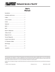
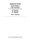
Component Names and Their
Functions
1. PC Select Switch
Press this switch to select the host. PCs with
POWER LEDs out can also be selected if power
is being supplied to the switch device (one or
more host is ON).
2. Select LED
Lights up when the host is selected.
3. POWER LED
Lights up when the host is ON.
4. LOW POWER LED
The switch device monitors whether or not the
power voltage is normal. Connect the special AC
adapter when this LED lights.
5. Reset Switch
Normally, this switch is not used. Use this switch
when selection is not possible or when keyboard
or mouse cannot be operated. Gently push in by
the tip of a pointed object such as a propelling
lead pencil. Pressing this switch returns the
switch device to its initial state, and hosts can be
restored without being rebooted.
6. DIP Switches
These switches are used for selecting Hot Keys
and setting the layout of the keyboard in use.
7. HUB Port Connector
This connector is for connecting USB devices.
8. Mouse Connector (console)
Attach the mouse here.
9. KB Connector (console)
Attach the keyboard here.
10. KB/Mouse Connector
Connect this to the keyboard or mouse (PS/2)
port on the host with the special cable.
11. Monitor Connector
Connect this to the monitor port on the host with
the special cable.
12. USB Connector
Connect this to the USB port on the host with the
special cable.
13. Audio Connector IN1
Connect this to the PC’s Line Out jack.
(Do not attach to the PC’s Speaker Out jack)
14. Audio Connector IN2
Connect this to the PC’s Line Out jack.
(Do not attach to the PC’s Speaker Out jack)
15. Audio Connector Out
Connect this to the speaker.
16. Monitor Connector (console)
Attach the monitor here.
17. DC5V Connector
Attach the special AC adapter here.
Front Panel
Rear Panel
5
Installing the USB Bridge Software
Software Installation Procedure
Before attaching the switch device to the PCs, the following installation and setup steps must be
performed:
* The “Setup Program” referred to in this section is the “setup.exe” executable found on the supplied CD-ROM disk.
1. How the installation should proceed
The switch device may be used after following the steps outlined in (1)~(3), below.
(1) Run the Setup Program on the two PCs to which the switch device is to be attached. This installs
the required software (detailed in section 2. below).
(2) Set the required PC parameters (detailed in section 3. below).
(Refer to the manuals provided with the PC or OS for further details of the setup procedure)
(3)
For each of the connected PCs, check the network settings. The workgroup name in particular
should be the same on both PCs.
If required, setup file, folder and printer sharing.
Once steps (1) and (2) have been completed, the PCs may be attached to the switch device.
2. Installing the software
Following the steps given below, run the Setup Program on all PCs to which the switch device is to
be attached. This installs the required software.
* The following procedure is given as an example. The exact details may vary slightly according to
the OS, etc.
(3)
Without attaching the switch device to the PC’s USB port, turn the PC on, and wait for Windows
to start up.
Insert the provided CD in the PC’s CD-ROM drive.
Double click on the “setup.exe” in the CD-ROM, or select [Start] -> [Run…] then specify
“setup.exe” on the CD-ROM.
The Setup Program’s Installation Wizard starts up.
(4)
Click the [Next] button.
(1)
(2)
6
(5)
Specify where the Setup Program should be installed.
If the default installation location is to be accepted as-is, just click the [Next] button.
* To specify a different folder, click the [Browse] button, then select the desired folder.
The default installation folder is “C:\Program Files\USB\USB-USB Network Bridge v1.8.0.0”.
When installing on Windows 2000, a [Digital Signature] dialog will appear next. Click the [Yes]
button.
When installing on Windows XP, a Windows logo test warning is displayed. Click the [Continue]
button. (We have checked operations for you.)
(6)
Copying of the necessary files commences. Once copying has finished, the network settings will
be automatically completed in response to [New Hardware].
* If the Windows CD-ROM is requested, insert your Windows CD in the PC’s CD-ROM drive, then
click the [OK] button.
7
(7)
When the reboot screen appears, click the [Finish] button.
Rebooting the PC completes the installation of the required drivers.
After rebooting, connect the switch device. (After connecting the switch device, the [new hardware
detection wizard] may start up, in which case select [automatically install the required software] to
install the drivers.)
3. Setting up the PC
Setting up file, folder (drive, including external devices) and printer sharing.
(Refer to the manuals provided with the PC or OS for further details of the setup procedure)
Checking the network components
(1) Select [Start] -> [Settings] -> [Control Panel].
(2) In the [Control Panel], double-click the [Network] icon.
(3) In the [Network] dialog box, check that the [USB-USB Network Bridge Adapter],
[NetBEUI->USB-USB Network Bridge Adapter], [TCP/IP->USB-USB Network Bridge Adapter]
and [Client for Microsoft Networks] appear in the list of installed network components.
8
Turning on [File and printer sharing for Microsoft Networks]
(1) Click the [File and Print Sharing] button, and make sure that the [I want to be able to give others
access to my files] and [I want to be able to allow others to print to my printer(s)] check boxes are
checked.
(2)
Check that [File and printer sharing for Microsoft Networks] has been added to the list of installed
network components.
Setting the Computer name and Workgroup
(1) On the [Identification] tab, enter a [Computer name], [Workgroup] and [Computer Description].
Each of the PCs should be assigned the same
Workgroup, but given a different Computer name.
The Computer Description field may be filled in with
any extra information that may be pertinent, or left
blank if desired.
(2) Click the [OK] button and reboot the PC.
9
Setting up drive and folder sharing
(1) Double-click the Windows [Explorer] or [My Computer] icon.
(2) Right-click the icons of any drives (or folders) that you want to share, then select [Sharing] from
the popup menu.
(3)
On the Sharing Properties screen shown below, check the [Shared As] check-box, adjust the
[Share Name], [Comment], [Access Type] and [Passwords] settings as necessary, then click the
[OK] button.
Share Name: enter the name that you wish to be
displayed on the PC accessing the shared drive/folder.
Access Type: set the level of read/write access to the
shared drive/folder that is to be allowed.
Read-Only: allow read access only to the shared
drive/folder.
Full: allow full read/write access to the shared
drive/folder.
Depends on Password: allow read (and optionally write)
access to the shared drive/folder upon provision of the
correct password.
Passwords: set the password(s) required to access the
shared drive/folder.
(From a security standpoint, if file sharing is to be allowed,
the use of passwords to regulate access is recommended.)
Remember that it is not just folders on internal hard disks that may be shared, but also those on external hard disks. In
fact any and all folders accessible under the [My Computer] icon may be shared.
Setting up printer sharing
Connect any printers to be shared to a PC printer port or USB port (or even one of the ports on the
front of the switch device), then install the printer software as described in the printer’s user manual.
Sharing a locally connected printer
(1) Select [Start] -> [Settings] -> [Printers].
(2) All the connected printers are shown, so exactly as for file sharing, right-click the icons of
any printers that you want to share, and select [Sharing] from the popup menu.
Accessing a remote shared printer
(1) Select [Start] -> [Settings] -> [Printers].
(2) Double-click the [Add Printer] icon to start the [Add Printer Wizard].
(3) Select the [Network printer] radio button, then click the [Next] button.
10
(4)
Click the [Browse] button, find and select the printer that you wish to share, then click the
[Next] button.
(5)
The applicable printer driver is enabled, finishing the shared printer setup.
You may need to install the applicable printer driver if it has not yet been installed.
(Refer to the manuals provided with the PC or OS for further details of the setup procedure)
4. Accessing networked computers
(All file transfers or other access between networked computers should be performed the same as for a normally
networked Windows computer. Refer to the manuals provided with the PC or contact your PC’s maker for details.)
Double-click the [Network Neighborhood] or [My Network Places] desktop icon.
The names of any PCs connected to the switch device are shown.
Double-clicking the icon of the PC that you wish to access should show you a list of all the shared
folders on the target PC.
Refer to the section on “Setting up drive and folder sharing” for details of how to setup a shared
folder.
* Sometimes timing issues may cause the PC that you wish to access to not be visible. Try
reopening the [Network Neighborhood], or select [Refresh] from the [View] menu.
(1)
(2)
(3)
5. Uninstalling the software (deleting the program)
Proceed as follows when uninstalling the USB Bridge Software:
(1) Select [Start] -> [Settings] -> [Control Panel], then double-click the [Add/Remove Programs]
control panel icon.
(2) On the [Install/Uninstall] tab, scroll down the list of installed software to find and select “USB-USB
Network Bridge V1.8.0.0”, then click the [Add/Remove] button.
(3) You are asked to confirm that you wish to delete the “USB-USB Network Bridge V1.8.0.0”
software. Click the [OK] button.
If you do not wish to delete the USB Bridge software, just click the [Cancel] button.
(4) The uninstaller starts up, and the program files are deleted.
After the uninstallation finishes, you are asked to reboot the PC. Click the [Yes] button.
This completes the removal of the USB Bridge driver and all related files. If you later decide to use
this software again, consult section 2 “Installing the software” and reinstall and setup the software
as before.
11
6. Troubleshooting the installation
Checking the USB controller and network adapter
(1) Select [Start] -> [Settings] -> [Control Panel], then double-click the [System] control panel icon.
(2) Double-click the [Universal serial bus controller] item (toward the bottom of the device list).
(3) Check that the “USB-USB Network Bridge Driver” shows up toward the bottom of the list of
controllers.
(4) Similarly, check that the “USB-USB Network Bridge” appears toward the bottom of the [Network
adapters] list.
* If a USB Bridge icon is showing a “!” mark, this means that it was not installed correctly, and
needs to be reinstalled.
Checking the PC settings
Even if the USB Bridge software has been installed correctly, stable operation cannot be
guaranteed if the PC settings themselves are not correct.
If you think this might be the cause of problems, try checking the settings described in section 3
“Setting up the PC”.
12
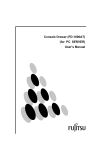
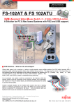
Connecting the PCs
1. Start by turning the PCs off.
(1)
(2)
Speaker
(4) (3)
2.
1) Connect the KB/Mouse connector of the
1st host to the KB/Mouse connector on the
switch device. Be sure to connect the host
side first, then the switch device. (Connect
(2).)
This connection is not required when the
switch device is to be used only on the
USB port.
2) Connect the USB connector on the host to
the USB connector on the switch device
using the special cable. Be sure to connect
the host side first, then the switch
device.(Connect (3).)
This connection is not required when the
USB port is not used.
When both (2) and (3) are connected, the
USB port and USB Bridge function are
used for HUB functions, and keyboard and
mouse data is sent from the KB/Mouse
connector (PS/2).
3) Connect the monitor connector on the host
to the monitor connector on the switch
device using the special monitor cable. Be
sure to connect the host side first, then the
switch device. (Connect (4).)
4) Connect the Line Out jack on the host to
one of the Audio Connector IN jacks on the
switch device using an audio cable.
(Never connect the PC’s Speaker Out jack,
as this can cause damage.)
5) Connect the 2nd host in the same way.
6) Next, connect the special AC adapter
when the switch device is connected to the
USB port. (Connect (5).)
7) Next, connect the console
(keyboard/mouse/monitor/speaker).
(Connect (6).)
(5)
(6)
(6)
■ NOTE ■
Use a 3-wire power code cable, and connect the
earth cable to the terminal.
When you use a 2-wire type adapter, be sure to
ground the earth wire.
13
Installing the USB HUB, USB Keyboard and USB Mouse drivers
Initial setup is required when connecting with a USB port.
The required drivers are contained in OS.
Therefore, it is not necessary to newly prepare.
The setup procedure for Windows98
(1)
(2)
(3)
Turn the PC on, and wait for Windows 98 to start.
Connect the switch device to the host (refer to page 5 for details).
When the [Add New Hardware Wizard] window appears, click the [Next] button.
(4)
Select [Search for the best driver for your device (Recommended).], then click the [Next] button.
(5)
When the following screen appears, click the [Next] button.
14
(6)
After searching for and finding the required driver, the following screen should appear. Click the
[Next] button.
(7)
When the driver installation has completed, the following screen should appear. Click the [Finish]
button.
(8)
This process will need to be repeated three times, once each for the keyboard, mouse and HUB.
This completes the initial setup procedure. Hereafter the devices should be automatically recognized and
usable whenever the USB cable is connected.
The setup procedure for Windows2000, Windows ME, & Mac OS.
No manual setup is required.
15
FS-102ATL Application Examples
File Sharing
Use of the Network Sharing Service provided by the Microsoft OS
allows data to be shared and files copied between the two PCs.
[Required Software]
Microsoft Network
[Acquisition Method]
Standard with OS
Internet Connection Sharing
Connecting to the Internet via a dialup connection or similar
(this example uses an internal modem)
Windows 98SE and ME allow a single internet connection to be
shared by multiple networked computers.
This allows 2 PCs to access the Internet via a single ISP connection.
[Required Software]
Internet Connection Sharing
[Acquisition Method]
Standard with Windows98SE/ME
USB device sharing
Sharing of USB devices connected to the FS-102ATL allows them
to be used by both PCs.
16
Printer & Storage Device Sharing
Sharing of USB devices connected to the FS-102ATL allows them
to be used by both PCs.
[Required Software]
Microsoft Network
[Acquisition Method]
Standard with OS
Printer
MO/CD-R(W)
How to Select the Host PC
There are two ways of selecting the host: by the Select switch on the switch device or from the
keyboard (Hot Key mode).
You can also select an unconnected port or the port of a host that is OFF.
If a selected PC is turned OFF, the selected state is changed another PC.
1. Selecting with the Select Switch
Press the Select switch. This switches to the selected PC, and the PC Select LED lights up.
2. Selecting with the keyboard (Hot Key Mode)
The Hot Key Mode provides the following three key operations. These operations can be enabled
(turned ON) and disabled (turned OFF) by the DIP switches (switches 1 to 3) on the switch
device.
SW1-ON
: Ctrl, Alt and Shift simultaneously held down
SW2-ON
: Ctrl key pressed twice consecutively
SW3-ON
: Scroll Lock key pressed twice consecutively
Select the host by the above Hot Keys.
17
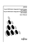
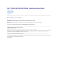
Key layout diagram
ASCII keyboard for Mac (PS/2)
Standard layout (DIP switch 5,6)
The functions of the keys with thick borders are changed.
The setup of the DIP switch is set to Mac. (Refer to page 18.)
Note that the crossed out key is disabled.
Extended layout (DIP switch 7)
<Win> key and <Alt> key can be replaced by setup. (Refer to page 18.)
Note that the crossed out key is disabled.
18
About the Special AC Adapter
When the switch device is connected to the USB port for use, the special AC adapter must be
connected. However, when the switch device is used only on the keyboard/mouse port (PS/2 port), the
configuration is designed so that this special AC adapter is not required. However, connecting power
consuming keyboards and mice may drop the power voltage.
In such cases, the LOW POWER LED turns on (Orange); connect the special AC adapter.
1. Use only the AC adapters specified by Fujitsu. Using an incompatible AC adapter may not only
affect the operation of the switch device, but also may cause it to malfunction. Operation using a
non-compatible AC adapter is not guaranteed.
2. Power supply from the special AC adapter is automatically turned OFF when the power of all PCs
is OFF. If the switch device will not be used for a long period of time, unplug the special AC
adapter from the outlet for safety.
DIP Switches
DIP Switch
SW1
SW2
SW3
SW4
Function
ON
Hot Key: simultaneous [Ctrl] + [Alt] + [Shift] Enabled (*)
Hot Key: double [Ctrl] key strike
Enabled (*)
Hot Key: double [ScrLk] key strike
Enabled (*)
Key layout (only valid if USB port is used)
European layout
ASCII layout (*)
SW5
Select PC or Mac for USB Port1
PC (*)
Mac
SW6
Select PC or Mac for USB Port2
PC (*)
Mac
SW7
Win and Alt key mappings for Mac KB
WIN => Command WIN => Option
SW8
USB Bridge Function
OFF
Disabled
Disabled
Disabled
Alt => Option(*)
Alt => Command
Enabled (*)
Disabled
(*) shows the default DIP switch setting.
Specifications
Item
Model (Name)
Connectable Host
Units Connected
Selection Method
LED Display
KB
Console
Mouse
Port
Monitor
Speaker
Host Port
KB/Mouse
Monitor
Speaker
USB
HUB port (rated power)
Monitor Resolution, Band Width
External power supply (special
AC adapter)
Power Consumption
Operating Environment
Storage Environment
Construction
Dimensions, Weight
(excluding cables)
Specification
FS-102ATL (KVMA Switch)
PC/AT compatible machine, Macintosh(USB)
Max. 2
Select Button, keyboard (Hot Key Mode)
POWER x 2, Select x 2, LOW POWER x 1
PS/2, Mini DIN 6P Female x 1
PS/2, Mini DIN 6P Female x 1
Mini D-SUB 15P Female x 1
Audio Line Out jack x 1 (connect to internal amp speaker)
PS/2, Mini DIN 6P Female x 2
Mini D-SUB 15P Female x 2
Audio Line In jack x 2 (connect to PC Line Out jacks)
Series “B”, Female x 2
Series “A”, Female x 2 (500mA/port)
1600 x 1200, 200MHz
DC + 5V ± 5% (supplied by DC5V connector)
Max. 150 mA
0 to 40°C, 20 to 90 %RH
- 20 to 60°C (condensation not allowed)
Mold casing (condensation not allowed)
148 (H) x 115(D) x 39.6 (W), mm/380g
19
Options
●
Special cable set
Model No.
Specification
High-definition monitor cable (3.0 m)
FS-C103A
Keyboard/mouse divider cable (3.0 m)
High-definition monitor cable (3.0 m)
SW2FS-C103U
USB cable (3.0 m)
Audio cable (3.0m)
FS-C103S
●
Monitor conversion connector for Mac
Model No.
NC14003-T044/ADP
Specification
DB15(M) < >DB15HD
Troubleshooting
Symptom
LOW POWER LED
lights up
KB, Mouse is inoperable
(special type
programmable/cord-less
/ wheel mice)
Scroll function or buttons
do not work on the
mouse.
Poor screen quality
(Faded images, blurred
characters, etc.)
Window shifts or does
not display when
switching
Cannot go into Hot Key
Mode
Cause
Large power-consuming keyboards or
mice are connected.
Keyboard and mouse are connected in
reverse.
Cannot get out of Hot Key Mode
Wrong monitor and keyboard/mouse
port Nos.
Connection/cable is defective
A non-supported keyboard or mouse is
connected.
Mouse not supported
The specific mouse driver is not
installed.
Connection/cable is defective
Wrong resolution
Unsupported monitor, or cannot
synchronize
The DIP switches are set to OFF.
Slow Consecutive Hot Key repeat
interval
Hot Key operation was performed on
USB keyboard connected to HUB port.
20
Action
Connect the special AC adapter.
Correct the connection.
Press the [Enter] or [ESC] key
Match the port Nos.
Confirm the connector connection.
Replace with a different cable. If this
solves the problem, replace with a
new cable.
Replace with a supported keyboard
or mouse.
Replace with a supported mouse.
Install the specific mouse driver.
Confirm the connector connection.
Replace with a different cable.
Adjust the resolution or use the
monitor function.
Replace with a supported monitor
(multisync).
Use the monitor function.
Set the DIP switches on the bottom
panel to ON.
SW1: [Ctrl], [Alt] and [Shift]
simultaneously held down
SW2: [Ctrl] key pressed twice
continuously
SW3: [Scroll Lock] key pressed
twice continuously
Repeat the key press slightly faster.
Hot Key operation is disabled as it is
enabled only on PS/2 keyboards.
Symptom
Keys used in the
application cannot be
used.
The switch device
suddenly stops.
The switch device LED
does not come on even
though the host is on.
No operation on USB
port
USB Bridge function
does not work correctly
Cause
The keys used in the application conflict
with the Hot Keys.
Action
Set the conflicting keys to OFF.
The cable is disconnected.
Switch device has frozen
An error has occurred in host
The power circuit protection element for
the host's keyboard/mouse port is
damaged.
The Special AC adapter is not connected
when using the switch device on the
USB port.
The special AC adapter is not
connected.
DIP SW8 is in the OFF position.
Required software is not yet installed, or
has not been installed correctly.
Connect the cable and reboot.
Press the reset switch.
Correct the problem in the host.
Correct the problem in the host.
It is rare, but problems can sometimes
occur if a host has other network
connections active.
USB Bridge software
can not be installed on
Windows2000
Inadequate user level permissions.
21
Connect the special AC adapter.
Connect the special AC adapter.
Switch it to the ON position.
Install the software.
If necessary, uninstall any
previously (but incompletely)
installed software, and install again.
Disconnect the host from any other
networks, or set DIP SW8 to the
OFF position to disable the Bridge
function.
Install as an Administrator level
user.
Declaration of Conformity
Model Number
: NC14003 series
Trade Name
: KVM Switch
Responsible party
: FUJITSU COMPONENT AMERICA, INC.
Address
: 250 East Caribbean Drive, Sunnyvale,CA94089
Telephone number : (408) 745-4900
This device complies with Part 15 of the FCC Rules. Operation Is subject to the following two
conditions : (1) this device may not cause harmful Interference, and (2) this device must accept any
Interference received, Including Interference that may cause undesired operation.
22
DOC Class B