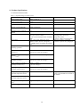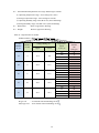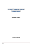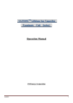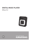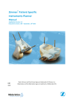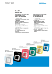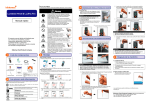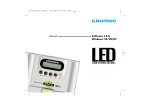
1
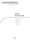
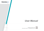
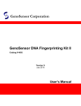
ULTIMO Module
MLB series
MPA series
Operation Manual
JMMC-11023 Version 1.01
March 15th, 2012 issue
JM Energy Corporation
1
SAFETY PRECAUTIONS
The following marks indicate notes you should pay attention to in this documentation. Please read these notes
and understand their contents before using the product.
■ This User’s Manual uses the following marks to explain safety precautions.
Danger
Misuse of the product “would very likely result in death or
serious injury.”
Warning
Misuse of the product “might result in death or serious injury.”
Caution
Misuse of this product “might result in injury or property damage.”
■ The following marks indicate rules for you to observe.
This indicates a “prohibited” action.
This indicates a “must” action.
About this User’s Manual
1. No part or whole of this Manual may be reprinted without approval.
2. Contents of this Manual may be changed without notice.
3. Every effort was made to ensure the accuracy of the contents of this Manual. Should you have any
questions, or notice inaccuracies or omissions, please contact us.
4. We are not responsible for anything that occurs due to actions contrary to the instructions of this Manual.
5. After reading this Manual, please keep it in a safe place and have it with you for reference whenever you
use the product.
2
Danger
Do not disassemble, or alter the ULTIMO module. The cover must be firmly
fixed
with screws when in use.
● Doing so may result in electric shock, injury, smoke, explosion, or ignition.
Do not heat the module or expose it to open flame
● Doing so may result in smoke, explosion, or ignition.
Wear a protective gear such as insulated gloves when handling the conductive terminals.
● Failure to do so may result in electric shock, burn, or injury.
3
Warning
Do not short-circuit the terminals.
● Doing so may result in electric shock, burn, or injury, and may also lead to a unit
breakdown with liquid leakage, heat, smoke, explosion, or ignition.
● Pay special attention to short-circuiting when using a metal tool.
Do not subject ULTIMOTM to excessive shock or vibration.
● Doing so may result in internal short-circuiting, liquid leakage, and unit breakdown.
Do not put ULTIMO module on an electromagnetic cooking device, or in a microwave
oven or a high-pressure container.
● Doing so may result in liquid leakage, explosion, or unit breakdown.
Do not use the product outside the range of its voltage specification.
● Using the product at a voltage outside the specification may shorten its life, and may
lead to liquid leakage, heat, smoke, explosion, or ignition.
If liquid leakage, odor, smoke, deformation, gas release valve actuation or other
abnormal situations occur, stop using the product immediately.
● Damage to the unit may result in heat, smoke, ignition, electric shock or injury.
Should leaking liquid enter your eyes, do not rub your eyes. Rinse them well with tap water
(clean water) and seek immediate medical attention. Should you swallow the contents, rinse
your mouth with water, and seek immediate medical attention..
4
Caution
ULTIMOTM has polarity (positive and negative). Use the correct polarity
● Incorrect use of polarity may result in liquid leakage, heat, smoke, explosion, or ignition.
Should leaking liquid stains the clothes, rinse it away immediately with tap water (clean water).
Upon receiving your product, please make sure there is no deformation, liquid leakage, odd
odor, heat, or any other abnormal condition. Should you find any abnormal condition upon
receiving the product, please do not use it. Contact us immediately.
About Transportation
Do not subject ULTIMO module to excessive shock or vibration during transit.
Do not do excessive accumulation of the packing box.
Do not expose the module to: rainwater, ocean water, snow ice, condensation, or
freezing conditions.
The voltage of the ULTIMO Module must be maintained in its specified operating
range.
5
Index
SAFETY PRECAUTION
1.Summary - - - - - - - - - - - - - - - - - - - - - - - - - - - - - - - - - - - - - - - - - - - - - - - - - - - - - -7
2. Appearance - - - - - - - - - - - - - - - - - - - - - - - - - - - - - - - - - - - - - - - - - - - - - - - - - - - - -7
3. Module location requirements - - - - - - - - - - - - - - - - - - - - - - - - - - - - - - - - - - - - - - - - 8
4.Moving and transport directions -- - - - - - - - - - - - - - - - - - - - - - - - - - - - - - - - - - - - - - -9
5. Storage directions - - - - - - - - - - - - - - - - - - - - - - - - - - - - - - - - - - - - - - - - - - - - - - - - -9
6. Configuration Diagram - - - - - - - - - - - - - - - - - - - - - - - - - - - - - - - - - - - - - - - - - - - - 10
7. Connection of charge and discharge circuit - - - - - - - - - - - - - - - - - - - - - - - - - - - - - - -11
8. Connection
8.1 Charge/Discharge Circuit - - - - - - - - - - - - - - - - - - - - - - - - - - - - - - - - - - - - - - - -12
8.2 Control Circuit - - - - - - - - - - - - - - - - - - - - - - - - - - - - - - - - - - - - - - - - - - - - - -12
9. Configuration- - - - - - - - - - - - - - - - - - - - - - - - - - - - - - - - - - - - - - - - - - - - - - - - - - - 12
10. Maintenance - - - - - - - - - - - - - - - - - - - - - - - - - - - - - - - - - - - - - - - - - - - - - - - - - - -12
11. Product Specification- - - - - - - - - - - - - - - - - - - - - - - - - - - - - - - - - - - - - - - - - - - - - 13
12. Contact us - - - - - - - - - - - - - - - - - - - - - - - - - - - - - - - - - - - - - - - - - - - - - - - - - - - - 15
6
1.Summary
This lithium-ion capacitor module (referred to as the module or the product herein after) has the voltage
monitor function for each cell and has the function to adjust for balanced operation among cells. If the module
detects any cell exceeding the upper/lower operating voltage limits, it sends out an excessive discharge or
over-charging alarm signal, and indicates the need to control the discharge or charging.
If any cell exceeds or does not meet the voltage range that is set in advance, FET switches are turned ON and a
resistive discharge is performed to attain the voltage balance among cells and keep the voltage within the set
limits.
2.Appearance
Fig.1 Appearance
(+) Positive
Terminal
(+) Positive
Terminal
(-) Negative Terminal
(-) Negative Terminal
MLB series (Laminate cell)
MPA series (Prismatic cell)
7
3. Module location requirements
Do not use in or near flammable or combustible liquids or vapors
An explosion or fire might be caused. Do not use it in in close contact with the combustible and
flammable liquids such as alcohol and thinner or their vapors.
Do not expose to temperatures outside the specified operating temperature range, heating
apparatus or direct sun light
Operating temperature range :- 30℃ to 70℃
Do not use in caustic or corrosive environments.
These environments may cause corrosion inside the module which may lead to a malfunction
or fire.
Avoid direct contact with water and high humidity conditions
Use only in the humidity range of: 90%Rh or less (non-condensing)
Do not use if dew or condensation are present..
Avoid contact with salt water liquid or vapors
Contact may result in metal corrosion.
Do not use in locations with excessive dust.
Dust may lead to an electric shock or fire.
Do not place any mass or weight on the module
To avoid damage from dropping, use only in a secure upright position .
Do not place the module in strong magnetic or electric fields.
This may cause the module to malfunction.
8
4. Moving and transport directions
Remove all external connections to the module
Do not carry the terminal block.
It may cause the injury by damage or the fall of product.
Please keep the cover attached in proper position.
There may be an electric shock or injury.
Do not subject the module to excessive vibrations or impact while transportation.
Regulations for Air Transport
Currently, Lithium ion capacitor or its module is not classified as a hazardous material under the 2011
IATA regulation. However, air transport regulations may change. Before packing for air transport,
check the latest transport regulations to ensure the correct means of packaging and transportation.
5. Storage directions
Charge the module voltage to more than 3V per cell but less that 3.8V per cell.
IE: a module with 6 cells should be charged to a voltage above 18V but less than 22.8V
Set the module in the keeping mode by the dip switch and the reset switch inside of front panel to
suppress power consumption. (Please refer to user's guide 6.2.7 for details.)
Protect the terminal not to touch by mistake.
Keep it in the place that is appropriate for clause 3 above after removing all the connected
wirings.
9
6. Configuration Diagram
The example configuration diagram of ULTIMO module is shown in figure2.
Fig.2 Configuration Diagram
Charge switch
Power
Supply
Discharge switch
+
+
-
-
Over charge alarm
Over temperature alarm
Load
Over discharge alarm
Over temperature alarm
DC9~36V
+
-
Over charge alarm
Ultimo
Master
module
control
unit
Over discharge alarm
Over temperature alarm
Sleep request
Wakeup request
Attention request
・
・
・
・
・
・
・
・
・
・
・
・
+
・
・
・
・
・
・
-
Ultimo
module
To protect the module in case of over-charge, over-discharge or abnormal temperature, use
power supply or load which has a shutoff function or a switch to disconnect charge and
discharge
10
7. Connection of charge and discharge circuit
Figure 3 shows a basic connection of the charge and discharge circuit.
Fig.7.1
Charge and Discharge circuit diagram
Power
Load
Supply
+
-
ULTIMO
Module
Connect the power supply and the load to the module by the most efficient way possible in
order to minimize voltage drop by interconnection resistance.
Insure the gauge of electric wire used is appropriate for the current.
-When the electric wire is inapposite, there may be overheating, fire or a large voltage
descent of the electric wire.
The terminals and the cable shall be surely connected at the torque of 4 to 4.5Nm with M6
bolt.
-A loose connection may generate heat, which could lead to a fire.
Operate the charge in accordance with the charger’s manual when you use a conventional
charger.
-Inproper use may result in breakdown, liquid leakage, generation of heat, smoke,
explosion, ignition, or damage.
Wear protective equipment such as insulation gloves for electric shock prevention.
Connect the positive and the negative terminals correctly.
Do not short-circuit the positive and negative terminals.
Do not impress excessive surge.
Control the module voltage to prevent overcharge and over discharge.
11
8. Connection
8.1 Charge and discharge circuit
Connect modules based on the wiring diagram of Figure 2. Up to 12 modules can be connected in series.
Confirm there is no voltage difference among modules which are connected in series.
Make connections only after confirming the charge/discharge switch (or, power supply and
load) is disconnected.
Use protective equipment (insulation gloves and insulating mat, etc.) which are appropriate
for the voltage.
8.2 Control circuit (In/Out signal)
Please refer to the following for the connection of the control circuit (In/Out signal).
-In case of four or less modules’ series connection
User’s guide clause 5 [External connection]
-In case of five to twelve modules’ series connection
User’s guide (Master control unit) clause 6 [External connection]
9. Configuration
The dip switch and the jumper connector shall be set as described in clause "7.Setting Dip SW and Others" of
the user's guide. However, it is already set if your module have such indications on the module itself.
10. Maintenance
We recommend ULTIMO module to be maintained on a regular basis when it is continuously used.
-Check the voltage to insure it is within the specifications range.
-Check if any distinctive abnormal conditions such as deformation, liquid leakage, abnormal odor, etc.
-Check the tightness of connections.
Should you find an abnormal condition, stop using the unit. Contact us immediately.
12
11. Product Specifications
11.1 Electrical Characteristics
Table 11.1 Operation Range of Control Section
Item
Specifications
Usable voltage range
Refer to Table.11.2
Usable current range
300A
Capacitance
Refer to Table.11.2
Internal resistance(DC-IR)
Under examination
Maximum series connection
number
Output signals
12
Input signals
Voltage difference for starting
balancing operation
Remark
VCEO=20V IC=100mA(max.)
(Tr open collector output)
* No current limiting resistor at module
side
VF=1.15V(TYP, 30mA>IF>15mA)
(Photo-coupler, input at issuing side)
* 780Ω resistor provided at the module
side
30mV
Voltage for issuing over-charge
alarm(VOV)
3.85V +/- 20mV
(by any one of the cell voltages)
Return voltage for over-charge
alarm(VOVOFF)
3.75V +/- 20mV (all cell voltages)
Voltage for issuing excessive
discharge alarm(VDC)
2.15V +/- 20mV
(by any one of the cell voltages)
Return voltage for excessive
discharge alarm(VDCOFF)
2.25V +/- 20mV
(all cell voltages)
Stopping voltage for excessive
discharge detection (VSP)
2.10V +/- 20mV
(by any one of the cell voltages)
Temperature for issuing the
abnormal temperature alarm
68ºC
Temperature for canceling the
abnormal temperature alarm
60ºC
Voltage monitor time period
(tWK)
Approximately 5 min.
Sleep time(tSLP)
Approximately 24 hrs.
Over-charge alarm, excessive
discharge alarm, abnormal
temperature alarm.
* See the output circuit paragraph.
WakeUP and Sleep commands
* See the “input circuit” paragraph.
Temperature is measured by one
sensor, in the middle of cell stack in
the module.
13
11.2 Environmental Requirements for Usage and Storage Locations
(1) Operating temperature range: -30 to 70 degrees Celsius
(2) Storage temperature range: -40 to 80 degrees Celsius
(3) Operating humidity range: 90% Rh or less (non-condensing)
(4) Storage humidity range: 90% Rh or less (non-condensing)
11.3 Dimensions
Refer to appearance drawing
11.4 Weight
Refer to appearance drawing
Table.11.2 Specification of module
Product Number : MPAxx x xxx x /MLBxx x xxx x
Product
Number
4th, 5th
Voltage Rating (V)
Number
of cells
Upper
Lower
15
4
15.2
8.8
22
6
22.8
13.2
30
8
30.4
17.6
38
10
38.0
22.0
45
12
45.6
26.4
Capacitance
typ(F)
7th, 8th, 9th
*Measurement condition of electrostatic capacitance
D type cell
:5A Constant Current Discharge at 25
F,G,H type cell :10A Constant Current Discharge at 25
14
275
550
575
825
183
367
383
550
138
275
288
413
110
220
230
330
92
183
192
275
Product
Number
10th
(cell type)
D
F
G
H
D
F
G
H
D
F
G
H
D
F
G
H
D
F
G
H
12. Contact
JM Energy Corporation
Tokyo sales office
Shiodome-Sumitomo Bldg
1-9-2 Higashi-Shinbashi, Minato-ku, Tokyo,105-8640, Japan
Phone: +81-3-6218-3615
JSR Micro N.V.
Technologielaan 8, 3001 Leuven, Belgium
Phone: +32-16-832-832
E-Mail: [email protected]
JSR Micro Inc.
1280 N. Mathilda Ave., Sunnyvale, CA, U.S.A.
Phone: +1-408-543-8983
<Revision History>
First Edition (October 11, 2011)
Partial Revision
15
Ver.1.01(March 15,2012)