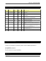
1
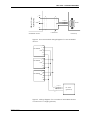
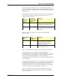
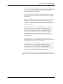
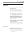
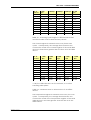
MCD 3000 – PROFIBUS GATEWAY
PROFIBUS Gateway
for MCD 3000 Series Soft Starters
P/N FS-1135
User Manual
Ver. 1.9
10 October 2003
© Copyright 2002 Fieldbus Specialists
MCD 3000
SERIES
1
USER MANUAL
MCD 3000 – PROFIBUS GATEWAY
REVISION NOTES
Index
Date
Chapte
r
Author
Rev.
Revision note
1
04-Feb-2002
All
AMcN
1.0
Created
2
11-Feb-2002
All
AJ
1.1
Various corrections
3
10-Mar-2002
All
AJ
1.2
Extended indications for invalid PROFIBUS
address
4
14-Mar-2002
2.6.2, 7
AJ
1.3
Local/Remote setting recommendations,
corrections to Specifications
5
4-April-2002
2.6.1
AKJ
1.4
Wiring diagrams added, mapping of read
memory corrected
6
5-MAY-2002
All
AmcN,
AJ
1.5
Unified format, added functions to handle
comm. breakdown
7
25-OCT-2002
AJ
1.6
Added comments related to Siemens S7
PLC
8
1-OCT-2003
JP
1.7
Added comments re. firmware version 2.02
and code compliance with Danfoss
manual AMB00000 Rev. G
9
9-OCT-2003
JP/AJ
1.8
Modified to reflect compliance with
AMB00000 Rev. G
10
10-OCT-2003
JP
1.9
Note re.byte sequencing in 2.10
TECHNICAL SUPPORT
In case of any questions or problems, please contact Fieldbus Specialists on
[email protected].
We will endeavour to reply immediately.
PREFACE
MCD 3000
SERIES
2
USER MANUAL
MCD 3000 – PROFIBUS GATEWAY
The data and illustrations in this manual are not binding.
Fieldbus Specialists reserve the right to modify our products in
line with our policy of continuous product development. The
information in this manual is subject to change without notice
and should not be considered as a commitment by Fieldbus
Specialists.
Fieldbus Specialists assume no responsibility for any errors that
may appear in this document.
Although this product has been developed with great care
and extensively tested, Fieldbus Specialists cannot guarantee
the suitability of this product for any purpose. Warranty claims
shall be limited to the right to require rectification of faults.
Liability for any damages, which may have arisen from the use
of this product or its documentation, shall be limited to cases of
intent.
MCD 3000
SERIES
3
USER MANUAL
MCD 3000 – PROFIBUS GATEWAY
CONTENTS
1
INTRODUCTION ............................................................................................................................. 6
1.1
1.2
2
IMPORTANT USER INFORMATION ............................................................................................................... 6
GENERAL .................................................................................................................................................. 6
INSTALING THE GATEWAY .......................................................................................................... 8
2.1
2.2
2.3
2.4
2.5
GATEWAY CONNECTION DIAGRAM............................................................................................................ 8
FRONT PANEL ........................................................................................................................................... 9
INSTALLATION SEQUENCE ....................................................................................................................... 11
POWER CONNECTION .............................................................................................................................. 11
PROFIBUS CONNECTION....................................................................................................................... 12
2.5.1
Cabling ..........................................................................................................................................12
2.5.2 GATEWAY CONFIGURATION ................................................................................................................... 13
2.6 MCD3000 CONNECTION......................................................................................................................... 14
2.6.1
2.6.2
3
PROGRAMMING THE MASTER CONTROLLER ........................................................................ 18
3.1
3.2
3.3
3.4
3.5
3.6
3.7
4
Cabling ..........................................................................................................................................14
MCD3000 configuration .............................................................................................................16
GSD FILE ................................................................................................................................................ 18
DECLARING MODULES ............................................................................................................................ 18
SETTING PROFIBUS PARAMETERS ........................................................................................................ 19
MASTER-SLAVE DATA EXCHANGE .......................................................................................................... 21
DATA WRITE AREA .................................................................................................................................. 21
DATA READ AREA ................................................................................................................................... 22
ISSUING COMMANDS .............................................................................................................................. 24
OPERATION OF THE GATEWAY ................................................................................................ 29
4.1
4.2
4.3
SCANNING SLAVES .................................................................................................................................. 29
SCANNING TIMES .................................................................................................................................... 29
OFFLINE SLAVES ..................................................................................................................................... 31
5
SPECIFICATIONS ......................................................................................................................... 32
6
TROUBLESHOOTING .................................................................................................................. 33
MCD 3000
SERIES
4
USER MANUAL
MCD 3000 – PROFIBUS GATEWAY
Table List
Table 1 – LED Indication .......................................................................................................................................10
Table 2 – PROFIBUS socket pin assignment .......................................................................................................12
Table 3 – RS-485 pin assignment .........................................................................................................................14
Table 4 – MCD 3000 Local/Remote modes ..........................................................................................................17
Table 5 – MCD 3000, RS-485 baud rate values....................................................................................................17
Table 6 – MCD 3000 node address on RS-485 network.......................................................................................17
Table 7 – Gateway parameter, RS-485 link baud rate ..........................................................................................19
Table 8 – Gateway parameter, gateway operation on communication loss ..........................................................20
Table 9 – PROFIBUS Write / Out Memory in control module................................................................................22
Table 10 – Command result codes .......................................................................................................................22
Table 11 – PROFIBUS Read / In memory.............................................................................................................24
Table 12 – Valid commands..................................................................................................................................25
Table 13 – New Command / Command Acknowledge handshaking ....................................................................27
Table 14 – Result Ready / Result Acknowledge handshaking ..............................................................................27
Table 15 – Scanning cycle length for different baud rates and the number of MCD 3000 devices present..........30
Table 16 – Maximum time to detect return of an offline device .............................................................................30
Table 17 – Gateway specifications........................................................................................................................32
Table 18 – Troubleshooting guide.........................................................................................................................33
Figure List
Figure 1.
Figure 2.
Figure 3.
Figure 4.
Figure 5.
Typical diagram of a PROFIBUS network, a gateway and an RS-485 sub-network. ..............................8
Gateway front panel ................................................................................................................................9
Entering address via dip switches, an example ....................................................................................13
Recommended wiring diagram for one MCD3000 device.....................................................................15
Wiring diagram for a number of MCD3000 devices connected to a single gateway.............................15
MCD 3000
SERIES
5
USER MANUAL
MCD 3000 – PROFIBUS GATEWAY
1
INTRODUCTION
1.1 Important user information
This manual describes operation and programming of a
PROFIBUS gateway for MCD3000 series soft starters, gateway
firmware revision 2.11.
Gateway with firmware version 2.11 complies with MCD3000
protocol as described in Danfoss manual AMB00000 Rev. G
and is likely to be incompatible with earlier versions of the soft
starter. Remote programming of parameters is not supported
at the moment. Contact Fieldbus Specialists if you require a
firmware version that supports earlier models.
Observe all the necessary safety precautions when controlling
any MCD 3000 series device over the serial communications
link, including alerting personnel that the machinery may start
without warning.
1.2 General
The MCD 3000 series of solid state soft starters incorporate a
serial communications facility that allows for the remote
control and interrogation of the MCD 3000 from an intelligent
host (master) via a multi-drop RS-485 communications network
using a proprietary protocol, specific to MCD 3000 devices.
The RS-485 link may be used to interface a MCD 3000 device to
a PROFIBUS network using the PROFIBUS to MCD 3000 gateway.
The PROFIBUS Master can then control any connected MCD
3000 device – start it, stop, reset trip conditions and read
operational status, motor conditions or trip status.
The PROFIBUS to MCD 3000 Gateway is a certified PROFIBUS
slave device. A number of gateways and other PROFIBUS
slave devices can be connected to the same network, subject
only to standard PROFIBUS limitations.
The gateway is a master on the RS-485 multi-drop MCD 3000
communications network. Up to 30 MCD 3000 devices may be
connected to a single Gateway. In this way up to 30 MCD
3000 devices will share one PROFIBUS address on the PROFIBUS
communications network.
This manual describes how the PROFIBUS to MCD 3000
gateway operates, how to connect MCD 3000 series soft
starters to the gateway and how to connect and operate the
gateway on a PROFIBUS network.
MCD 3000 SERIES
6
USER MANUAL
MCD 3000 – PROFIBUS GATEWAY
When reading this manual, it may help to refer to the MCD
3000 Operating Instructions, Danfoss document no. AMB00000.
MCD 3000 SERIES
7
USER MANUAL
MCD 3000 – PROFIBUS GATEWAY
2
INSTALING THE GATEWAY
2.1 Gateway connection diagram
The diagram below shows how the gateway is connected to
the PROFIBUS network and to the RS-485 sub-network.
PROFIBUS DP
Master
PROFIBUS network
MCD 3000
Gateway
DP Slave
DP Slave
RS-485 sub-network
MCD 3000
device
MCD 3000
device
MCD 3000
device
MCD 3000
device
Figure 1. Typical diagram of a PROFIBUS network, a gateway
and an RS-485 sub-network.
A gateway can coexist with a number of other PROFIBUS
nodes, including other gateways. Each gateway constitutes a
single PROFIBUS node, even if it connects to a number of MCD
3000 devices.
MCD 3000 SERIES
8
USER MANUAL
MCD 3000 – PROFIBUS GATEWAY
2.2 Front panel
4
6
MCD 3000 - PROFIBUS Gateway
FS-1135
5
RS485
STATUS
ADDRESS
1 2 3 4 5 6 7 8
ON
POWER
LSB
1
3
PROFIBUS
STATUS
RS485
+ _
24V DC
PROFIBUS
2
Figure 2. Gateway front panel
Fig. 2 shows the front panel of the gateway. Located on the
front panel are:
1. RS-485 sub-network connector for connecting up to 30
MCD 3000 devices, DB9, male,
2. PROFIBUS network connector, DB9, female,
3. Power connector, 2 pin removable terminal block,
4. Bi-colour PROFIBUS status LED,
5. Bi-colour RS-485 status LED,
6. Dip switches for PROFIBUS address selection.
The following table indicates the status of the PROFIBUS
connection.
MCD 3000 SERIES
9
USER MANUAL
MCD 3000 – PROFIBUS GATEWAY
PROFIBUS
LED
RS-485
LED
Gateway status
Gateway starting (max. 6 sec) or no power
B
B
R/B
ANY
Invalid PROFIBUS address
R/B
ANY
PROFIBUS link down – no PROFIBUS Master,
incorrect address or no connection,
G/R/B
ANY
PROFIBUS link error – wrong configuration or
parameter in Master
G
ANY
PROFIBUS link up and problem-free
ANY
R/B
No communication on the RS-485 link
ANY
G/R
Occasional errors on the RS-485 link
G
G
Both PROFIBUS and RS-485 links operational
and error-free
Legend:
B
G
- LED off
- LED steady green
R/B
-
LED flashing red/off
G/R
-
LED flashing green/red
G/R/B
-
LED flashing green/red/off
ANY – applies irrespective of LED status
Table 1 – LED Indication
These simple rules may be worth remembering:
-
MCD 3000 SERIES
Flashing indicates errors on the relevant link,
Flashing red means that the gateway attempts to
communicate but fails every time,
Flashing red/green means that the gateway can
communicate, but errors occur.
10
USER MANUAL
MCD 3000 – PROFIBUS GATEWAY
2.3 Installation sequence
When installing the gateway, we recommend the following
sequence:
!
Connect power, see section 2.4 for details. If there are no
indications of power, check voltage and polarity.
!
Set the PROFIBUS address on dip switches, configure and
activate PROFIBUS master, see section 2.5 for instructions.
Configure the PROFIBUS master for one MCD device only.
On success the PROFIBUS status LED will go green, on error
it will blink red. If the LED stays red, check the cable,
address on the gateway and address setting in the
master. If the LED flashes green/red, verify the
configuration of modules in the PROFIBUS master. Do not
proceed further until you get the PROFIBUS LED steady
green.
!
Configure and connect the first MCD 3000 device, set it to
address 1, see section 2.6 for details. On success, the RS485 status LED should go green. We recommend initially
to configure PROFIBUS master for only one MCD device
connected to the gateway and to get this configuration
working successfully. Later on you can increase the
number of MCDs. If the RS-485 status LED stays solid red,
check the RS-485 cable, the MCD 3000 device
configuration (set to Local), wiring to MCD 3000 and the
value of the PROFIBUS parameter in the gateway
configuration data in PROFIBUS master – RS-485 subnetwork baud rate setting.
!
Configure and connect the remaining MCD 3000 devices,
make also the relevant changes to the configuration of
PROFIBUS master. On success the RS-485 LED should go
solid green. If it flashes green/red, one or more MCD 3000
does not communicate with the gateway.
2.4 Power connection
The gateway requires 24V DC power, approx. 130mA. The
voltage can be unregulated – the gateway will operate
correctly for power voltage in the range 12-32V. The current
drawn changes with voltage – it is ~240mA for 12V and ~90mA
for 32V. The power connector is a removable terminal block,
2-pin. The device is reverse polarity protected – in the case of
reversed connection it will not get damaged but it will not
operate either.
MCD 3000 SERIES
11
USER MANUAL
MCD 3000 – PROFIBUS GATEWAY
Presence of correct power can be verified by looking at the
LEDs on the front panel – at least one LED should be illuminated
at all times, whether green or red.
2.5 PROFIBUS connection
The PROFIBUS socket of the PROFIBUS to MCD 3000 Gateway
must be connected to a PROFIBUS network in accordance
with PROFIBUS Technical Guideline “Installation Guideline for
PROFIBUS DP/FMS”, PROFIBUS International Order No. 2.112.
2.5.1
Cabling
The PROFIBUS to MCD 3000 Gateway connection requires a
PROFIBUS cable with DB9, male connector. Pin assignment in
the PROFIBUS socket is as follows:
DB9 socket Pin
Purpose
1
Shield/functional ground
2
Not connected
3
RXD/TXD-P (Data Line)
4
Not connected
5
Data ground (reference potential for VP)
6
VP – supply voltage, +5V
7
Not connected
8
RXD/TXD-N (Data Line, Inverted)
9
Not connected
Table 2 – PROFIBUS socket pin assignment
Pins 3 (RXD/TXD-P) and 8 (RXD/TXD-N) must be connected. The
other pins can be used, if needed.
The gateway does not provide termination on the PROFIBUS
cable. If the gateway is located at either end of the cable,
the termination resistors should be provided externally, usually
in a PROFIBUS plug with the termination option. The gateway
provides termination power on pins 5 and 6.
The shield on the PROFIBUS socket is galvanically connected to
the metal top lid on the enclosure. An earthing lug is provided
for earthing the top lid. When the PROFIBUS cable plug is in the
MCD 3000 SERIES
12
USER MANUAL
MCD 3000 – PROFIBUS GATEWAY
socket, the shield on the PROFIBUS cable is connected with the
socket shield, the top lid and the earthing lug.
2.5.2
Gateway configuration
The gateway automatically detects the baud rate for the
PROFIBUS network. All standard baud rates are supported as
per PROFIBUS Specification, up to 12 Mbits/s.
The PROFIBUS node address of the PROFIBUS to MCD 3000
Gateway is configured with an 8-way DIP switch that is located
on the front panel of the gateway. The address must be set to
a value that is not in use by any other device on the PROFIBUS
network. Valid address range – 0 to 125.
The procedure for setting the node address of the gateway is
as follows:
!
Ensure that the device is not powered up by unplugging
the power connector.
!
Set the DIP switches to the desired value (see figure
below).
!
Reinsert the power connector
Fig. 1 shows the location of the DIP switches on the front panel.
These switches are used to enter the address, with the most
significant bit on the left and the least significant bit on the
right. The address is entered in binary, with the switch in up
position for ‘0’ and in the switch in the down position for ‘1’.
For example, to set the address “3”, binary 0000 0011, the
switches need to be positioned as follows.
ADDRESS
1 2 3 4 5 6 7 8
ON
LSB
Figure 3. Entering address via dip switches, an example
In addition to setting the address, it is necessary to define the
gateway’s configuration in the PROFIBUS Master. For detailed
description of this important stage, refer to section 3.
MCD 3000 SERIES
13
USER MANUAL
MCD 3000 – PROFIBUS GATEWAY
2.6 MCD3000 connection
2.6.1
Cabling
The MCD 3000 devices should be connected to the RS-485
serial sub-network as per the MCD 3000 Operating Instructions.
The gateway is connected to the RS-485 sub-network using a 9
pin male DB connector, located to the left side of the
enclosure. Pin assignment is as the following table indicates.
Pins not listed there are unused or reserved and MUST NOT be
connected.
Pin Number
Purpose
1
+ Signal
5
Shield/Ground
9
- Signal
Table 3 – RS-485 pin assignment
We recommend using a shielded twisted pair cable. When the
gateway is located away form the soft starter, the
communications cable should be shielded and should not be
run in the vicinity of high current power cabling. It is advisable
to fit termination resistors at each end of the cable to match its
characteristic impedance, typically in the range of 100-120
ohm.
The recommended connection diagram is shown in fig. 4
below. We recommend connecting cable shield on the
gateway side only and we recommend that the connection
point 61 on the MCD3000 device be left unconnected.
MCD 3000 SERIES
14
USER MANUAL
MCD 3000 – PROFIBUS GATEWAY
SERIAL COMM.
PORT RS485
68
+
to pin 1
to pin 5
to pin 9
61
GND
_
RS485
69
cable shield
MCD3000 device
Gateway
Figure 4. Recommended wiring diagram for one MCD3000
device.
MCD3000
+
GND
_
MCD3000
+
GND
_
MCD3000
+
GND
_
68
61
69
68
61
69
68
61
69
to pin 1
to pin 5
to pin 9
FS-1135
gateway
Figure 5. Wiring diagram for a number of MCD3000 devices
connected to a single gateway
MCD 3000 SERIES
15
USER MANUAL
MCD 3000 – PROFIBUS GATEWAY
If a number of MCD3000 devices are connected to a single
gateway, we recommend wiring them in series, see fig. 5. The
cable should constitute a single line, without side branches.
Note that we recommend connecting GND points (61) on all
MCD 3000 devices to guarantee that they share the same
ground potential. If the devices are connected to the
common ground in some other way (ex. via a metallic
mounting), it may not be necessary to connect points 61.
RS-485 interface on MCD3000 is not galvanically isolated.
Failure to equalize ground potential on MCD 3000 devices
connected via RS-485 link may result in their damage.
2.6.2
MCD3000 configuration
The gateway can communicate at any of the baud rates that
MCD 3000 devices can support. All MCD 3000 devices
connected to the same sub-network must be configured for
the same baud rate.
Each MCD 3000 device must be configured with a node
address. Each must have a different address and each
address must be in the range 1 to the number of MCD 3000
devices connected to the gateway, inclusive. Example: if four
devices are connected to a gateway, they must have
addresses 1, 2, 3 and 4.
Each MCD 3000 Local/Remote Mode parameter (Parameter
20) must be set to 0, 1 or 2. Setting this parameter to 3 disables
the RS-485 communications port. For more detailed
explanation refer to the MCD 3000 Operating Instructions.
MCD 3000 devices must be set for “Local” operation using the
Local/Remote pushbutton on the front panel. When this is
done, the LED labeled “REMOTE” on the front panel is off.
NOTE: When the MCD3000 device is set for “Remote”, it does
not execute commands received over the RS-485 link.
However, it still acknowledges these commands.
Consequently, the gateway and the PROFIBUS master cannot
detect this condition. For working with a gateway, we
recommend to set Local/Remote Mode parameter (Parameter
20) to 2 – “Local control only”. This will eliminate the possibility
of the MCD3000 device being set for “Remote” accidentally or
by mistake.
The MCD 3000 devices must be configured using the keypad/
LCD display on its front panel. The method of setting
MCD 3000 SERIES
16
USER MANUAL
MCD 3000 – PROFIBUS GATEWAY
parameters is described in details in the MCD 3000 Series Soft
Starter Operating Instructions.
The following tables show the required configuration for the
MCD 3000 soft starter parameters relevant to the operation of
the gateway.
Parameter 20
Local/Remote Mode
Configuration Options
Default Setting
0
Local/Remote enabled
1
Local/Remote enabled
only when motor stopped
2
Local control only
3
Remote control only
0
Local/Remote enabled
Table 4 – MCD 3000 Local/Remote modes
Parameter 22
Serial communication baud rate
Configuration Options
1
1200 baud
2
2400 baud
3
4800 baud
4
9600 baud
5
19200 baud
4
9600 baud
Default Setting
Table 5 – MCD 3000, RS-485 baud rate values
Parameter 23
MCD 3000 address for RS-485 serial
communications
Configuration Options
1 – 99
Required Setting
A number between 1 and the total
number of MCD 3000 devices on the
network
Table 6 – MCD 3000 node address on RS-485 network
MCD 3000 SERIES
17
USER MANUAL
MCD 3000 – PROFIBUS GATEWAY
3
PROGRAMMING THE MASTER CONTROLLER
3.1 GSD file
Information on the technical characteristics of the gateway is
loaded into PROFIBUS master software by means of a GSD file.
A floppy disk with the GSD file is supplied with the gateway. The
GSD file name is “FS1135.GSD”. Follow the instructions in the
PROFIBUS configuration/management software manual for
loading the GSD file and adding the new slave, the gateway,
to the network.
If you need a copy of the GSD file, please contact us at
[email protected].
For the PROFIBUS Master to communicate with the gateway, it
must be provided with information about the way that the
gateway works. You can do it by following these steps:
!
load the GSD file, for details refer to the manual for
master configuration software,
!
declare the required modules within the gateway,
!
set PROFIBUS parameters of the gateway.
3.2 Declaring modules
The gateway is a modular PROFIBUS slave, consisting of several
modules as defined in the GSD file. The gateway must be
configured with the control module declared first, and then
with one slave module declared for each soft starter
connected to it.
The control module has 10 bytes of input data and 3 bytes of
output data, no consistency. This module is declared in the
GSD file with the “Preset” keyword and many configuration
applications will automatically declare it as required and in the
correct position – as the first module in the configuration.
Check that the software you are using supports the “Preset”
keyword and if not, declare this module manually as the first
one in the configuration data of the gateway.
In addition to the control module, you must declare a slave
module (5 Bytes In, module consistency) for each MCD 3000
device connected to the gateway. The gateway assumes
MCD 3000 SERIES
18
USER MANUAL
MCD 3000 – PROFIBUS GATEWAY
that the addresses of the MCD 3000 devices start at 1 and are
consecutive, up to the number of expected devices.
The first motor starter module relates to the MCD 3000 with
address 1, the second one to 2 and so on. Address values are
not related to physical positioning of MCD 3000 devices on the
RS-485 sub-network.
NOTE for users of SIMATIC S7:
Motor starter modules are defined as so called “modules with
data consistency”. This is necessary to guarantee accuracy of
current reading. The consequence of it in S7 is that module
data cannot be read directly – direct reading always returns 0.
Instead, you should use SFC14 to cyclically copy module data
to PLC internal memory and then retrieve the required values.
In case of problems consult an S7 expert re. the memory
addresses to be used for motor starter modules and the correct
way of retrieving module data.
3.3 Setting PROFIBUS parameters
The gateway requires three parameters, associated with the
control module in the gateway configuration. The first
parameter defines the desired baud rate on the RS-485
network. The gateway supports all the baud rates that the
MCD 3000 devices support:
First Parameter
Value
Baud Rate
1
1,200 bps
2
2,400 bps
3
4
4,800 bps
9,600 bps (Default)
5
19,200 bps
Table 7 – Gateway parameter, RS-485 link baud rate
MCD 3000 SERIES
19
USER MANUAL
MCD 3000 – PROFIBUS GATEWAY
The second parameter defines gateway operation if
communication with the master stops:
Second
parameter
Action on communication
breakdown
1
Stop polling MCD3000
devices
STOP command sent to all
MCD3000 devices
2
3
COAST TO STOP sent to all
devices
Table 8 – Gateway parameter, gateway operation on
communication loss
The selected action will be executed when the gateway had
established initial communication with the master and
subsequently this communication stops.
If the second parameter is set to 1, the gateway will stop
poling MCD3000 devices on communications breakdown. This
may cause MCD3000 devices to trip, if they are so
programmed (Parameter 24). For other values of this
parameter, the gateway will keep on polling and will prevent
MCD3000 tripping.
The third parameter defines the timeout, in seconds, for
communication with the master.
If the gateway stays off-line on PROFIBUS for the time period as
set in the third parameter, the gateway will take action as
defined by the second parameter. Allowed range is 0 to 255.
Default value is 5, setting the timeout at 5 sec. If the third
parameter is set to 0, no timeout supervision will be carried out
and once communication with master commences, the
gateway will keep on polling MCD3000 devices irrespective of
the status of gateway-master link.
On receiving an invalid parameter value or invalid
configuration data from the PROFIBUS master, the gateway
goes offline and flashes the PROFIBUS status LED green, red and
then turns it off. After a few seconds the PROFIBUS master will
try again to set the gateway to ONLINE state and the cycle
repeats until the error is corrected.
MCD 3000 SERIES
20
USER MANUAL
MCD 3000 – PROFIBUS GATEWAY
3.4 Master-slave data exchange
Data exchanged between PROFIBUS master and slave are of
two types – configuration data and process data.
Configuration data are transmitted once only when the master
establishes communication with the slave. These data carry
information about slave configuration – the modules declared
there. Also included in the configuration data are parameters,
sent from master to the slave. In case of the MCD3000
gateway, the configuration data instruct the gateway about
the number of MCD 3000 devices to scan, about the baud
rate on the RS-485 network and about required action if the
gateway goes off-line on PROFIBUS. Master controller
generates the configuration data autonomously and the PLC
has no control over their transmission or content.
Process data are the data transmitted cyclically between the
master and slave. The PLC writes the data for the slave to the
Write area and reads the data from the slave from the Read
area. Locations of the Write and Read areas in the PLC
memory are specific to each PLC. For details consult the PLC
manual.
3.5 Data write area
The only write data (data transferred from PROFIBUS master to
the gateway) are contained in the control module – 3 bytes of
data. These three bytes are used to issue commands to
MCD3000 devices, as described later in this manual.
The first byte is the Master Handshake Register. Only the two
least significant bits B0 and B1 are used, the other six bits are
ignored by the gateway. Meaning of the value of bits B0 and
B1 is explained later in this document.
The second byte is the Command Register. When PROFIBUS
master controller issues a command to a MCD3000 device, it
writes the code of the command to the Command Register.
Table 9 below shows all the valid values – command codes that can be written to the Command Register and the
commands associated with these values. The values in the
table are shown in hexadecimal. These values have been
chosen to resemble the original command codes as used by
MCD3000 devices. For example, the ASCII command code for
Stop is “B12”. The hexadecimal value selected for Stop is B2
(hex), 0xB2 in C language notation and 1011 0010 in binary.
The third byte – Address Register – contains the RS-485 subnetwork address of the MCD device that the command is for.
MCD 3000 SERIES
21
USER MANUAL
MCD 3000 – PROFIBUS GATEWAY
Offset
Contents
Comments
0
Master
Handshake
Register
Bit B0: New Command Bit.
Bit B1: Result Acknowledge Bit.
1
Command
Register
see Table 12 below
2
Slave Address
Register
Address of the slave that the
command is for.
Table 9 – PROFIBUS Write / Out Memory in control module
3.6 Data read area
Read data (data that the PROFIBUS master reads from the
gateway) come from the control module – 10 bytes – and from
each slave module defined for MCD 3000 devices – 4 bytes for
each MCD 3000. Actual memory addresses depend on
programming of the master controller, so in the following
description we refer to offsets, where the very first byte in a
module is assumed to have offset 0 and the subsequent bytes
within the module follow.
The first byte in the control module – offset 0, Slave Handshake
Register – operates in the way similar to the Master Handshake
Register. Only the bits B0 and B1 are used. More detailed
explanation can be found later in this document.
The second byte at offset 1 carries the code of the outcome of
the command – 1 for success, error codes 2, 3 or 4 in case of
failure, see the table below for details.
Result code
1
2
3
4
Description
Successful completion
The gateway rejected the command – invalid
command code or data
No reply from the target or target rejecting the
command
Invalid target address
Table 10 – Command result codes
The next four bytes (at offsets 2 to 5) carry information about
network status of devices on the RS-485 sub-network. The first
byte (at offset 2) relates to addresses 1-8, the second to 9-16,
the third to 17-24 and the fourth to 25-30. Four bytes are
always reserved, irrespective of the number of slaves present.
When bit B0 in byte at offset 2 is set, it indicates that the
MCD3000 device with address 1 is present and
MCD 3000 SERIES
22
USER MANUAL
MCD 3000 – PROFIBUS GATEWAY
communicating. Similarly, bit B1 set indicates slave 2 present.
A bit set to 0 means that the corresponding slave is not present
or not communicating. Bits related to slaves not declared on
the network are always set to 0.
All data related to a slave (status data, trip codes, current and
temperature) are valid only if the relevant network status bit is
set.
The four bytes at offsets 6-9 are used for commands that return
data, such as Request Status. The content of these bytes is the
same as the content of the data part of a reply received from
the MCD3000 devices, refer to the MCD 3000 Series Soft Starter
Operating Instructions for more details.
Slave modules have 5 read bytes each, one block for each
MCD3000 device. The structure of each 5-byte block is the
same, see Table 11. This table assumes consecutive
placement of modules in master’s memory. If your master
controller places modules differently, the offset values will be
different.
The value in Status_1 register is read from the MCD3000 device
and then inverted, to yield positive logic – 1 meaning YES/TRUE
and 0 meaning NO/FALSE.
The value in Trip register is as described in the starter manual.
The value in two-byte Current register is an unsigned integer in
the range 0-9999, with the first byte being the least significant
one and the second byte being the most significant.
The last byte – Temperature register - carries information about
motor’s temperature, given as percentage of the motor’s
thermal capacity, range 0 to 250%, encoded as an unsigned
integer. If the MCD3000 device reports motor temperature
greater than 250%, the gateway will report 250%.
As a general rule, all unused bits or bytes are always set to 0.
Table 11 shows the structure of the Read area for a controller
that allocates modules consecutively in memory. For other
controllers, such as S7, the values of offset start from 0 for each
module and placement of consecutive modules in PLC
memory can be arbitrary.
MCD 3000 SERIES
23
USER MANUAL
MCD 3000 – PROFIBUS GATEWAY
Offset
5-byte block
for address 1
Contents
Comments
0
Slave Handshake
Register
Bit Bit B0: Command Ackn. Bit
Bit Bit B1: Result Ready Bit
1
Command Result
Register
1: Success.
2: Invalid/rejected Command.
3: No/rejected response from
slave.
4: Invalid slave Address
2
Online Slaves Register
1
Bit B0: Slave 1 online.
…
Bit B7: Slave 8 online.
3
Online Slaves Register
2
Slave 9 online - Slave 16 online.
4
Online Slaves Register
3
Slave 17 online - Slave 24 online.
5
Online Slaves Register
4
Slave 25 online - Slave 30 online.
6-9
Data Read Registers
Command Data Reply
10
Status for address 1
Status_1 value for device at
address 1
11
Trip for address 1
Trip value for device at address 1
12-13
5-byte block
for address 2
*Current for address 1
Motor Current, 0 – 9999 Amps.
14
Temperature for
address 1
Motor Thermal Capacity, 0 – 250%
15
Status for address 2
As above
16
Trip for address 2
As above
*Current for address 2
As above
Temperature for
address 2
As above
17-18
19
…
…
…
…
…
…
5-byte block
155
Status for address 30
As above
for address 30
156
Trip for address 30
As above
*Current for address
30
As above
Temperature for
address 30
As above
157-158
159
Table 11 – PROFIBUS Read / In memory
3.7 Issuing Commands
PROFIBUS master can issue commands to each MCD 3000 at
any time. The following Table 12 lists the commands as well as
the purpose of these commands. The commands are shown in
hexadecimal notation.
MCD 3000 SERIES
24
USER MANUAL
MCD 3000 – PROFIBUS GATEWAY
Command
Action
0xB0
Start Motor
0xB2
Stop Motor
0xB4
Reset Trip State
0xB6
Coast To Stop
0xC0
Read Status
0xC2
Read Status_1
0xC6
Read RS-485 Protocol Version
0xC8
Read Trip Status
0xD0
Read Current
0xD2
Read Temperature
0xFF
Read Gateway Firmware
Revision
Table 12 – Valid commands
This is the procedure for issuing a command:
!
Write the slave address into the Slave Address Register
(Control module, Write data, byte at offset 2),
!
Write the command into the Command Register (Control
module, Write data, byte at offset 1),
!
As the last step, toggle the Command Request Bit in the
Master Handshake Register (Control module, Write data,
byte at offset 0) - change the bit from 0 to 1 or from 1 to 0
- so that it is different from the Command
Acknowledgment Bit in Slave Handshake Register.
Then the following happens:
MCD 3000 SERIES
!
The gateway toggles the Command Acknowledge Bit in
Slave Handshake Register (Control module, Read data,
byte at offset 0) to make it the same as the Command
Request Bit. This indicates an acknowledgement of the
command (but not its completion).
!
When the command processing has finished, whether
successfully or not, the gateway places the results into the
Command Result Register (Control module, Read data,
byte at offset 1).
!
In the last step the gateway toggles the Result Ready Bit in
Slave Handshake Register (Control module, Read data,
byte at offset 0), indicating the completion of the
command as well as the availability of the results.
25
USER MANUAL
MCD 3000 – PROFIBUS GATEWAY
This is how Master can read the outcome of the command:
!
Upon detecting change of value of the Result Ready Bit,
PROFIBUS Master should read the Command Result
Register (Control module, Read data, byte at offset 1).
!
If the command was “Read Status”, “Read Status_1” or
“Read Trip Status”, PROFIBUS master should also read the
Data Read Registers. These are bytes at offsets 6 through
to 9 in the Control module Read data. The content of
these four bytes is the same as the four bytes that MCD
3000 device sends in reply to the equivalent command,
refer to the MCD 3000 device Operating Instructions for
details.
!
If the command was “Read Gateway Firmware Revision”,
PROFIBUS Master should retrieve the content of the Data
Read Registers, bytes at offsets 6-9 in Control Module. The
firmware revision is encoded as four ASCII characters.
Example – for Rev. 2.02, the content of the four data bytes
will be ‘0’ (0x30), ‘2’ (0x32), ‘1’ (0x31) and ‘0’ (0x30).
!
As the last step, PROFIBUS Master should toggle the
Command Acknowledge Bit in the Master Handshake
Register (Control module, Write data, byte at offset 0) to
indicate to the gateway that the result/reply has been
read.
PROFIBUS master must NOT issue a command until:
-
the gateway has acknowledged the previous command –
bits B0 in Master and Slave Handshake Registers are equal,
whether 0 or 1,
-
the reply to it has been acknowledged – bits B1 in Master
and Slave Handshake Registers are equal, whether 0 or 1.
Status of the motor can be affected by a number of factors
other than commands. Consequently, you MUST NOT assume
that the motor is in any particular state even if a command has
been accepted and returned Success in Command Result
Register. To monitor status of the motor, the master controller
should continuously monitor Status register.
An attempt to issue a command before the gateway has
acknowledged and responded to the previous one will be
ignored and may lead to an unpredictable behaviour of the
gateway.
On startup, the PROFIBUS Master should set the Master
Handshake Register to 0. The gateway resets Slave Handshake
Register to 0 while not on PROFIBUS network. This guarantees
MCD 3000 SERIES
26
USER MANUAL
MCD 3000 – PROFIBUS GATEWAY
proper startup conditions for the handshaking mechanism. We
recommend that PROFIBUS Master program checks the correct
startup conditions – bits B0 and B1 in both handshake registers
being equal.
The tables below show possible combinations of handshaking
bits and their meaning. Symbol X means either 0 or 1, /X
means the opposite to X.
New
Command
Bit (B0)
Command
Acknowledge
Bit (B0)
Meaning
X
/X
Bits are different. PROFIBUS Master
has issued a command, but the
gateway has not accepted it yet.
X
X
Bits are the same. No command or
the gateway has accepted the
command.
Table 13 – New Command / Command Acknowledge
handshaking
Result Ready
Bit (B1)
Result
Acknowledge
Bit (B1)
Meaning
X
/X
Bits are different. The gateway
placed command results in
PROFIBUS data and awaits the
master’s confirmation.
X
X
Bits are the same. No results or the
result has been read.
Table 14 – Result Ready / Result Acknowledge handshaking
It is the gateway’s responsibility to acknowledge the
command bits via the ‘Command Acknowledge Bit’. It is the
PROFIBUS master’s responsibility to acknowledge the result bits
via the ‘Result Acknowledge Bit’. Failure to follow the
handshaking procedure may lead to unpredictable behaviour
of the gateway.
Commands take precedence over scanning of slaves and will
be executed within 250 msec. If the PROFIBUS master detects
undue delay in gateway acknowledging the command or
sending a response, it should restart the gateway by placing it
in OFFLINE state and then returning it to ONLINE.
This is an example of the complete procedure for reading
status data of an MCD3000 device at address 3 using Read
Status command:
MCD 3000 SERIES
27
USER MANUAL
MCD 3000 – PROFIBUS GATEWAY
1. Check that the device is on-line, i.e. the network status bit
is set – in this case check Read byte at offset 2, bit B2. If this
bit is set to 1, you can proceed. If the bit equals 0, the
device at address 3 is offline.
2. Check that previous commands have been completed –
Master Handshake Register and Slave Handshake Register
are equal.
3. Write command code 0xC0 (Request Status) to Command
Register - byte at offset 1 in Write area. Also write slave
address 3 to Address Register – byte at offset 2 in Write
area. The sequence in which these bytes are being written
into is irrelevant.
4. Modify bit B0 in Master Handshake Register – change it
from 0 to 1 or from 1 to 0, whichever is applicable, to
indicate to the gateway that a command is pending. You
may monitor that bit B0 in Slave Handshake Register
changes to equal bit B0 in Master Handshake Register,
indicating that the gateway device accepted the
command. Be aware that this change does not have to
be immediate.
5. Wait for bit B1 in Slave Handshake Register to change,
indicating that a reply is waiting. This may take some time,
needed for execution of the command.
6. Read Command Result Register. If it equals 1, retrieve the
requested device status from Data Read Registers at
offsets 6 to 9. If Command Result Register equals 2, 3 or 4,
process the error. In either case, acknowledge the
response by modifying bit B1 in Master Handshake Register
to make it equal B1 in Slave Handshake Register.
For commands that do not return any data (such as Start or
Stop), there is no need to read Data Read Registers at offsets 6
to 9.
MCD 3000 SERIES
28
USER MANUAL
MCD 3000 – PROFIBUS GATEWAY
4
OPERATION OF THE GATEWAY
4.1 Scanning slaves
The gateway starts scanning slaves only after the PROFIBUS
Master sends the configuration data and the gateway
goes online on PROFIBUS.
The gateway periodically retrieves Status_1, Trip Code,
Current and Temperature from each slave and updates
the PROFIBUS process Read data in an autonomous
fashion. Status_1 and Trip Code are being read most
frequently – in each scan cycle, Current is read once every
third scan cycle and Temperature every tenth scan cycle.
On the first scan the Status_1, Trip Code, Current and
Temperature are read from all declared devices. The
device network status bits in the Read area, offset 2-5, are
set for all slaves that reply, refer to Table 11.
The addressing scheme for the MCD 3000 Soft Starters
assumes that the node addresses of all the MCD 3000
devices are in the range from 1 up to the number of
devices preset in the configuration. Devices with higher
addresses are not scanned.
If a slave fails to respond to a data request command, it is
considered an “Offline Slave” and has it’s corresponding
network status bit cleared. Also cleared are the process
data bytes related to this slave.
Note that Status_1, Trip code, Current and Temperature
process data for each slave in PROFIBUS master memory
are valid only if the relevant network status bit is set. If the
network status bit is not set, then the process data
associated with that particular slave are invalid.
4.2 Scanning times
The following Table 16 gives an indication of the time
required to complete a polling cycle for a number of slaves
present on a serial link over the supported baud rates. The
times are in seconds. These figures indicate possible delay
in detecting changes to Status_1 and Trip code – data
read in each scan cycle.
MCD 3000 SERIES
29
USER MANUAL
MCD 3000 – PROFIBUS GATEWAY
No. of
Devices
1,200
bps
2,400 bps
4,800 bps
9,600 bps
19,200
bps
1
0.500
0.300
0.190
0.130
0.110
2
1.000
0.600
0.380
0.260
0.220
3
1.500
0.900
0.570
0.390
0.330
4
2.000
1.200
0.760
0.520
0.440
5
2.500
1.500
0.950
0.650
0.550
10
5.000
3.000
1.900
1.300
1.100
15
7.500
4.500
2.850
1.820
1.650
20
10.000
6.000
3.800
2.600
2.200
25
12.500
7.500
4.750
3.120
2.750
30
15.000
9.000
5.700
3.900
3.300
Table 15 – Scanning cycle length for different baud rates
and the number of MCD 3000 devices present
The Current register is scanned once every three scan
cycles. Consequently, the average time between two
consecutive reads of the current register of the MCD 3000
devices is three times greater than the time as in the table
above.
No. of
Devices
1,200
bps
2,400
bps
4,800
bps
9,600
bps
19,200
bps
1
0.250*
0.250*
0.250*
0.250*
0.250*
2
5.000
3.000
1.900
1.300
1.100
3
7.500
4.500
2.850
1.950
1.650
4
10.000
6.000
3.800
2.600
2.200
5
12.500
7.500
4.750
3.250
2.750
10
25.000
15.000
9.500
6.500
5.500
15
37.500
22.500
14.250
9.750
8.250
20
50.000
30.000
19.000
13.000
11.000
25
62.500
37.500
23.750
16.250
13.750
30
75.000
45.000
28.500
19.500
16.500
* Only the offline device is on the network, so no other
scanning takes place.
Table 16 – Maximum time to detect return of an offline
device
The Temperature register is scanned once every ten scan
cycles. Consequently, the average time between two
consecutive reads of the Temperature register of the MCD
3000 devices is ten times greater than the time as in the
table above.
MCD 3000 SERIES
30
USER MANUAL
MCD 3000 – PROFIBUS GATEWAY
The gateway will automatically detect if a MCD 3000
device that was declared offline becomes available
again. The Table 16 above shows the worst case time for
detecting such a device, assuming that only one device
on the network is offline. The time is in seconds.
4.3 Offline slaves
Since up to 30 slaves can share the same RS-485 serial link,
it is critical that communication delays are kept to a
minimum. Slaves that are slow to respond slow down the
entire serial link. It is important that slaves that fail to
respond do not hold up the gateway. The following
scheme is used to handle offline slaves:
!
If a slave fails to respond to a command, it is
considered an offline slave and joins a list of offline
slaves, internal to the gateway.
!
In each polling cycle all online slaves are polled. After
5 polling cycles, a command is sent to one of the
offline slaves.
!
On a subsequent offline slave poll, the next slave on
the list of offline slaves is polled.
!
Once an offline slave responds to a command it is no
longer considered an offline slave.
This mechanism helps keep network delays to a minimum
while also being able to recover offline slaves when they
come online.
The above mechanism allows to connect/disconnect MCD
3000 devices while the network is working, with minimal
impact on the rest of the network.
MCD 3000 SERIES
31
USER MANUAL
MCD 3000 – PROFIBUS GATEWAY
5
SPECIFICATIONS
Item
Value
Enclosure
- Width
100 mm
- Height
75 mm
- Depth
110 mm
Mounting
DIN Rail or Screw
Mounting
PROFIBUS Interface
- Connector Type
9 Pin DB Female
- Galvanically Isolated
Yes (850V)
- Status Indicator (Type)
5mm Bi-Coloured LED
- Configured
Dip switches (Address)
MCD3000 Subnetwork Interface
- Connector Type
9 Pin DB Male
- Galvanically Isolated
Yes (1000V)
- Status Indicator (Type)
5mm Bi-Coloured LED
- Configured
Via PROFIBUS
Power
- Voltage
24V
- Consumption
3.2 Watts
- Connector Type
Removable Screw
Terminal
- Reverse Polarity Protection
Yes
- Surge / Short Protection
Fuse
Other Items
- Field Programmable
Yes
- Weight
Approx. 350g
- Protection Class
IP 20
Table 17 – Gateway specifications
MCD 3000 SERIES
32
USER MANUAL
MCD 3000 – PROFIBUS GATEWAY
6
TROUBLESHOOTING
Indications
Problem
Possible cause (check in the order listed)
LEDs all off for
extended period
No power
No power
Incorrect polarity
Gateway’s fuse blown
Both LEDs flashing red
PROFIBUS address
invalid
PROFIBUS address on DIP switches set
outside the valid range 0-125
PROFIBUS Status LEDs
flashing red,
No communication
with PROFIBUS Master
PROFIBUS Master is disconnected or off
PROFIBUS cable is cut/broken/not installed
correctly
PROFIBUS address set incorrectly
High inducted noise on the cable
PROFIBUS Status LEDs
flashing
green/red/off
Gateway
communicating with
PROFIBUS Master, but
unable to establish
data link
Incorrect gateway configuration
information in PROFIBUS Master, incorrect
parameter value
RS-485 Status LED
flashing red
No communication on
RS-485 link
RS-485 cable fault (cut/broken/not installed
correctly)
No devices are configured correctly for
operation over RS-485
No device addresses are set correctly
RS-485 Status LED
flashes red/green
Errors on RS-485 link,
but some
communication still
takes place
Some devices not present
Some devices are not configured for remote
operation over RS-485
Some device addresses are set incorrectly
Incorrect gateway configuration
information in PROFIBUS Master
PROFIBUS Master issues invalid
command/request
Table 18 – Troubleshooting guide
MCD 3000 SERIES
33
USER MANUAL