1
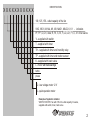
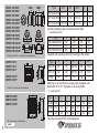
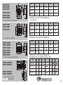
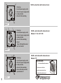
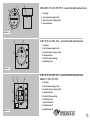
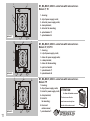
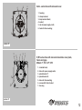
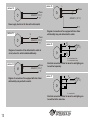
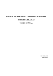
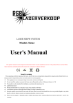
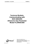
VENTS SERIES DOMESTIC
ELECTRIC FANS
User’s Manual
2008
DESIGNATION
BASIC SPECIFICATIONS
"VENTS" fans are designed for ventilation of domestic
and similar premises (apartments, offices, stores,
garages, kitchens, bathrooms, toilets and other rooms,
heated in wintertime).
Fans identification, diagrammatic representation of appearance,
installation dimensions and peculiarities of design are given
in Table 1.
Fans (but for VKO/VKO1 series) are exhaust fans and
are designed for wall or ceiling mounting.
MAO-series fans are to be installed
in windows.
VKO/VKO1-series fans may be used for both input and
output ventilation and are to be installed
in ventilation ducts.
VENTS fans are designed for continuous work without
switching off mains.
The fans are designed for operation from AC power supply with
voltage of 220-240 V and frequency of 50 Hz or 12 V
and frequency of 50 Hz (depends upon the model).
Nominal output in terms of extract air capacity is:
- for fans with 100 mm outlet capacity: 55 - 107 m3/h ( 5%)
- for fans with 125 mm outlet capacity: 108 - 232 m3/h ( 5%)
- for fans with 150 mm outlet capacity: 220 - 348 m3/h ( 5%)
Nominal electric power of the fans is:
for fans with 100 mm outlet capacity: - 5,3/22 W
for fans with 125 mm outlet capacity: - 9,1/26 W
for fans with 150 mm outlet capacity: - 20/32 W
Equalized sound level at 3 m distance does not exceed 40 dBA.
Fans are designed for operation at air temperature
within 0°Ñ to 45°Ñ.
Durability not less than 5 years.
Design of the fans is constantly improved and updated,
and some models may differ from what is described in this manual.
1
IDENTIFICATION
XXXXXXXXXXX
100, 125, 150 - outlet capacity of the fan
VKO, VKO1, M, MA, M1, M3, MAO1, MAO2, K, K1 - indication
PF, PF1, D, D1, Xstar, R, R1, S, S1, F, LD, LD1, F1, X, X1 of fan series
V - supplied with switch
T - supplied with timer
TH - supplied with timer and humidity relay
TP - supplied with timer and motion sensor
K - supplied with back valve
L - motor with ball-bearings
turbo
press
12 - low voltage motor 12 V
Q - quiet operation motor
Example of symbolic notation:
VENTS 125 DVTK fan with 125 mm outlet capacity, D-series,
supplied with switch, timer, back valve
2
D1
D/D**
c
l
l
100 VKO/VKO1 85/113
104
100/98
32
30
D**
VÊÎ
Type
125 VKO/VKO1 85/118
129
125/123
32
30
150 VKO/VKO1 105/128
154
150/148
48
30
VÊÎ1
D
D1
a**
à/a**
Mounting inside air duct connected on both sides.
** -series fans VKO1
f
h
e
h
e
f
VENTS 100 VKO*
VENTS 125 VKO*
VENTS 150 VKO*
VENTS 100 VKO1*
VENTS 125 VKO1*
VENTS 150 VKO1*
VENTS 100 VKOk*
VENTS 125 VKOk*
VENTS 150 VKOk*
VENTS 100 VKO1k*
VENTS 125 VKO1k*
VENTS 150 VKO1k*
g
g
Type
100 VKOk/VKO1k
125 VKOk/VKO1k
150 VKOk/VKO1k
å
160
185
200
g
144
169
184
h
29
29
29
f
45
45
45
*- VKO(k) and VKO1(k) - series fans of all modifications
Supplied with mounting corbel for mounting to flat surface.
VENTS 100 K*
VENTS 125 K*
VENTS 150 K*
Type
à
b
c/c**
D
e/e**
100 Ê/ K1
154
110
100/104
100
15/19
125 Ê/ K1
187
142
100/104
125
15/19
250
214
118
150
15
VENTS 100 K1*
VENTS 125 K1*
150 Ê
Mounting on air duct from air-charging side. Supplied with
detachable "Ê" or "Ê1" type grille on air-suction side.
*- K and K1- series fans of all modifications
** -series fans K1
a
b
c
f
g
VENTS 100 M3*
VENTS 125 M3*
VENTS 150 M3*
e
*- M3- series fans of all modifications
table 1
3
Type
à
b
c
D
e
f
g
100 M3
188
155
85
100
30
256
226
125 M3
188
155
91
125
30
256
226
150 M3
188
155
115
150
30
256
226
Mounting on air duct from air-charging side
a
c/c**
D
VENTS 100 D*
VENTS 125 D*
VENTS 150 D*
VENTS 100 D1*
VENTS 125 D1*
VENTS 150 D1*
VENTS 100 M*
VENTS 125 M*
VENTS 150 M*
ñ
b
D
a
VENTS 100 MA*
VENTS 125 MA*
VENTS 150 MA*
VENTS 100 M1*
VENTS 125 M1*
VENTS 150 M1*
å
*- MA and M1 -series fans of all modifications
a
e
c
D
b
ÌÀÎ1
ÌÀÎ2
h
VENTS 125 MAO2*
VENTS 150 MAO2*
*- MAO1 and MAO2 -series fans
of all modifications
c**
D
e
108/93
100
12
125 D\D1
176
140
114/96
125
13
150 D\D1
205
165
132
150
15
Type
à
b
c
D
e
100 Ì
160
135
90
100
25
125 Ì
180
150
94
125
25
150 Ì
207
182
106
150
25
Mounting on air duct from air-charging side
*- M -series fans of all modifications
table 1
b
120
** -series fans D1
*- D and D1 -series fans of all modifications
VENTS 125 MAO1*
VENTS 150 MAO1*
à
150
Mounting on air duct from air-charging side
e
b
Type
100 D\D1
Type
à
b
c
D
e
100 ÌÀ\M1
166
150
90
100
30
125 ÌÀ\M1
186
170
94
125
30
150 ÌÀ\M1
207
187
110
150
30
Mounting on air duct from air-charging side
MA supplied with automatically opening louvers.
à
e
c
b
Type
D
173
125 ÌÀÎ1
186
125 ÌÀÎ2
186
173
60
150 ÌÀÎ1
210
195
66
150 ÌÀÎ2 210 195
Mounting on the windows.
60
66
53
125
60
g
h
123
160
156
183
125
150
150
g
4
a
c/c**
D
VENTS 100 LD*
VENTS 125 LD*
VENTS 150 LD*
VENTS 100 LD1*
VENTS 125 LD1*
VENTS 150 LD1*
b
e
D
c
b
e
b/b**
* - PF and PF1 - series fans of all modifications
VENTS 100 F*
VENTS 125 F*
table 1
5
D
e
100
30
125 LD\LD1
176
140
134/116
125
30
150 LD\LD1
205
165
153
150
30
Type
à
b
c\c**
D
e
100 S\S1
150
120
108/93
100
12
125 S\S1
176
140
114/96
125
12
150 S\S1
205
165
132
150
13
** - series fans S1
ØD/D**
VENTS 100 PF1*
VENTS 125 PF1*
VENTS 150 PF1*
of all modifications
c\c**
126/111
Mounting on air duct from air-charging side
VENTS 100 PF*
VENTS 125 PF*
VENTS 150 PF*
* - F and F1- series fans
b
120
** - series fans LD1
a
* - S and S1 - series fans of all modifications
Type
à
b/b**
D/D**
D1
100 PF\PF1
12
99/127
100/99
141
125 PF\PF1
14
100/134
125/123
166
150 PF\PF1
15
116/146
150/146
188
Mounting on air duct from air-charging side
** - series fans PF1
D1
ØD/D**
e
D1
f
g
100 F\F1
182 160 99/127 100/99
10
141
252
226
125 F\F1
182 160 100/134 125/123 10
166
252
226
Type
ñ/ñ**
f
g
VENTS 100 F1*
VENTS 125 F1*
à
150
Mounting on air duct from air-charging side
* - LD and LD1- series fans of all modifications
VENTS 100 S*
VENTS 125 S*
VENTS 150 S*
VENTS 100 S1*
VENTS 125 S1*
VENTS 150 S1*
Type
100 LD\LD1
à
b
ñ/ñ**
D/D**
Mounting on air duct from air-charging side
** - series fans F1
g
D
VENTS 100 Õ*
VENTS 125 Õ*
VENTS 150 Õ*
c
b
a
* - X- series fans of all modifications
Type
à
b
c
D
g
100 Õ
151
96
30
100
120
125 Õ
178
101
30
125
140
150 Õ
204
117
30
150
165
Mounting on air duct from air-charging side
g
Type
à
b
c
D
g
100 Õ1
151
96
12
100
120
D
VENTS 100 Õ1*
VENTS 125 Õ1*
VENTS 150 Õ1*
c
b
a
* - X1- series fans of all modifications
125 Õ1
178
101
13
125
140
150 Õ1
204
117
14
150
165
Mounting on air duct from air-charging side
g
D
VENTS 100 Õstar
a
à
b
c
D
g
151
96
31
100
120
Mounting on air duct from air-charging side
c
b
Type
100 Õstar
b
D
VENTS 100 R*
c
a
h
Type
à
b
c
D
h
100 R
150
122
89
98
36
Mounting on air duct from air-charging side
* - R- series fans of all modifications
b
* - R1- series fans of all modifications
table 1
a
D
h
122
89
150
98
100 R1
Mounting on air duct from air-charging side
25
Type
D
VENTS 100 R1*
c
h
à
b
c
6
SAFETY REQUIREMENTS
M, D, D1, Xstar, S, S1, M1, M3, LD, LD1, X, X1
series fans can be supplied with back valves.
At that dimention of case outlet capacity
of fan is 14 mm longer.
fan
back valve
a
The fan VENTS complies with the requirements according to
the EU norms and directives, to the relevant EU-Low Voltage
Equipment Directives, EU-Directives on Electromagnetic
Compatibility.Level of protection from access to hazardous
parts and waterproof:
c
D
IPX4 - VKO , VKO1
IP24 - MA, Xstar, R, R1, MAO1, MAO2, X, X1 series
e
b
L= C + 14
SET OF SUPPLY
The following articles are included in the
supplied set:
- Fan - 1pc.;
- User’s manual;
- Packing box;
- Screws: 4pcs;
(except models 100, 125, 150 VKO/VKO1)
- sealing gasket - 2 pcs;
(for models 125, 150 ÌÀÎ1/ÌÀÎ2)
- tie-bolt - 2 pcs.
(for models 125, 150 ÌÀÎ1/ÌÀÎ2)
7
IP34 - K, K1, D, D1, M, PF, PF1,
M1, M3, F1, S, S1, F, LD, LD1 series.
Connection of fans supplied without electric cords to power
supply as well as replacement of electric cord should be
performed by skilled electrician.
Fan operation beyond the operational temperature range as
well as in rooms with ambient air containing aggressive
admixes is prohibited.
ATTENTION! Fan operation when restirictions, being able to
damage or jamm blades of operation wheel, are in flowing part
of case, is prohibited.
Precautions must be taken to avoid the black-flow of gases
into the room from the open flue of gas or other fuel-burning
appliances.
PREPARATION TO DEVICE OPERATION.
Attention! All maintenance works and connection of
fans are to be performed only after switching
off mains.
Connection of fans to electric power supply must be
performed only through switch with actuation length
not less than 3 mm at all poles.
Direction of air-charging is to comply with direction
of arrow on the fan case.
VENTS VKO\VKO1 fans are mounting in ventilation
air ducts from both ends and nipped with clamps.
VENTS MAO1/MAO2 fans are mounting
on the windows .
Fans of other models are inserted in the hole
of the air duct and mounted on the wall or
ceiling with dowels.
If necessary, ensure conditions to prevent free
access to impeller and current-carrying parts of
fan by protective means from side of outcome
(ventilation grille, protective cowl and so on).
Connection of fans to electric power supply
is shown in Fig. 1-11.
An order in which connection of fans should
be made is indicated in Tab.2
Fans Identification
Operations of connection to power supply
VENTS VKO
VENTS VKO1
VENTS Ê
VENTS Ê1
VENTS PF
VENTS PF1
VENTS F
VENTS F1
Remove protective grid (except model VENTS VKO).
Take away a protective cowl. Pass power supply cords
through a hole 3, smooth out wire rags at length 7-8 mm
to clamp terminals 4 agaist stop to the metal part of the
clamp and tighten them with screws. Fix cords with the
help of clip 2. Reinstall protective cowl and grid back.
VENTS M
VENTS M1
VENTS M3
VENTS MA
VENTS MAO1
VENTS MAO2
Remove protective grid and cover. Pass power supply cords
through a hole 3 (having cut a thin plastic pierce on the spot
of opening beforehand). Smooth out wire rags at length 7-8
mm to clamp terminals 4 agaist stop to the metal part of the
clamp and tighten them with screws. Fix cords with the help
of clip 2. Reinstall cover and protective grid back.
VENTS Xstar
VENTS D
VENTS D1
VENTS S
VENTS S1
VENTS LD
VENTS LD1
VENTS X
VENTS X1
VENTS R
VENTS R1
Remove protective grid and cover. Pass power supply cords
through a hole 3 (having cut a thin plastic pierce on the spot
of opening before hand). Smooth out wire rags at length 7-8
mm to clamp terminals 4 agaist stop to the metal part of the
clamp and tighten them with screws. Place power supply
cords into housing grooves and fix them in fastening support.
Reinstall cover and protective grid back.
Take off a decorative front facia (for models R). Open a cover
of terminal compartment. Put the wires through an opening 2
(having cut a thin plastic cover on the opening beforehand).
Skin the ends of the wires for 5-7 mm, set them in the
terminal 1 up to the stop of the isolation into metal part of
the terminal and fix them with screws. Set the power wires i
n the terminal compartment. Close the cover of the terminal
compartment. Mount the front facia (for models R).
table 2
For fans without switch, it is advisable to install power
supply switch on fixed power supply wiring.
Diagram of connection of fan to fixed power supply wiring is
shown in Fig. 12-17
8
5
1
M, M3 -series fans with removed cover.
1 - housing;
2 - clip of power supply cords;
2 3 - holes for power supply cords;
4 - clamp terminal;
5 - holes for fan mounting.
3
4
3
picture 1
1
6
5
1 - housing;
2 - clip of power supply cords;
3 - holes for power supply cords;
2 4 - clamp terminal;
5 - holes for fan mounting;
6 - timer\
timer with humidity sensor;
7 - pull cord switch.
3
7
4
M, M3 -series fans with removed cover.
Models: T, TH, V, VT, VTH
3
picture 2
1 - housing;
2 - clip of power supply cords;
3 - holes for power supply cords;
4 - clamp terminal;
5 - holes for fan mounting;
6 - timer with motion sensor;
7 - potentiometer T.
picture 3
9
M, M3 -series fans with removed cover.
Models: TP
ATTENTION
for fans with motion sensors
The front cover of the fan
must be uncovered only from
the side of the motion sensor !
3
4
VKO, VKO1, F1, K, K1, PF, PF1, F - series fans with removed cover.
3
1
1 - housing;
2 - clip of power supply cords;
3 - holes for power supply cords;
4 - clamp terminal.
2
picture 4
4
5
D, D1, S, S1, LD, LD1, X, X1, - series fans with removed cover.
2
1
6
3
1 - housing;
2 - clip of power supply cords;
3 - holes for power supply cords;
4 - clamp terminal;
5 - holes for fan mounting;
6 - lead fixing rack.
5
picture 5
5
9
D, D1, S, S1, LD, LD1, X, X1, - series fans with removed cover.
Models: T, TH, V, VT, VTH
4
2
1
6
3
8
picture 6
7
1 - housing;
2 - clip of power supply cords;
3 - holes for power supply cords;
4 - clamp terminal;
5 - holes for fan mounting;
6 - lead fixing rack;
7 - pull cord switch;
8 - potentiometer T;
9 - potentiometer H.
10
1
5
M1, MA, MAO1, MAO2 - series fans with removed cover.
Models: T, TH
6
1 - housing;
2 - clip of power supply cords;
3 - holes for power supply cords;
4 - clamp terminal;
5 - holes for fan mounting;
6 - potentiometer T;
7 - potentiometer H.
7
picture 7
2 3
4
5
1
5
1 - housing;
2 - clip of power supply cords;
3 - holes for power supply cords;
4 - clamp terminal;
5 - holes for fan mounting;
6 - pull cord switch;
7 - potentiometer T;
8 - potentiometer H.
8
7
picture 8
6
2 3
4
5
1
5
7
6
picture 9
11
4
2 3
M1, MA, MAO1, MAO2 - series fans with removed cover.
Models: V, VT, VTH
M1, MA, MAO1, MAO2 - series fans with removed cover.
Models: TP
1 - housing;
2 - clip of power supply cords;
3 - holes for power supply cords;
4 - clamp terminal;
5 - holes for
fan mounting;
6 - timer and
motion sensor;
7 - potentiometer T.
ATTENTION
for fans with motion sensors
The front cover of the fan
must be uncovered only from
the side of the motion sensor !
5
4
Xstar - series fans with removed cover.
6
1 - housing;
2 - clamp terminal;
3 - lamp terminal block;
4 - socket;
5 - clip of power supply cords;
6 - holes for fan mounting;
1
2
3
picture 10
5
3
4
1
2
L
LT
R, R1 series fans with removed decorative cover plate,
fascia and gags.
Models: T, TH, V, VT, VTH
N
6
7
1 - terminal block;
2 - holes for power supply cords;
3 - potentiometer T;
4 - potentiometer H.
5 - holes for fan mounting;
6 - screws to fix fan into duct
7 - housing
picture 11
12
picture 15
picture 12
L
Phase
LT
Phase
220-240 V ( 12 V *)
“0”
N
S
220-240 V ( 12 V *)
Power supply feed circuit for fans with built-in switch
“0”
picture 13
Diagram of connection of fan equipped with timer /timer
with humidity relay and without built-in switch.
S
Phase
220-240 V ( 12 V *)
“0”
picture 16
L
S1
Phase
220-240 V ( 12 V *)
“0”
N
Diagram of connection of fan without built-in switch to
circuit, where 8 is switch installed additionally.
L
S2
S1 - external switch of fan
S2 - external switch of lamp
picture 14
L
LT
N
Phase
220-240 V ( 12 V *)
“0”
Diagram of connection of fan equipped with timer /timer
with humidity relay and built-in switch.
Electrical connection of X star fan when fan and lighting can
be switched separately
picture 17
L
N
S
Phase
220-240 V ( 12 V *)
“0”
L
S - external switch
Electrical connection of X star fan when fan and lighting can
be switched at the same time.
13
Diagrams in Fig. 12, 14 show operation of fans, equipped with built-in switch.
Diagrams in Fig. 13, 15 show connection of fans without built-in switch. (S - external switch).
Electrical connection of X star fan is shown in Fig.16, 17.
Fan with timer option switches on when the voltage is supplied to clamp LT. After the voltage is disconnected the fan
continues working during the set time T, which is regulated from 2 till 30 min. The time T is regulated by turning the
potentiometer clockwise to increase and anticlockwise to decrease the delay time.
Fan with timer and humidity sensor switches on when the voltage is supplied to clamp LT
or when the definite humidity level (regulated from 60% till 90%) is exceeded. After the voltage is
disconnected or humidity level H is decreased the fan continues working during the time set by timer T,
which is regulated from 2 till 30 min. The options of time T and humidity H are regulated
by turning the potentiometers T and H clockwise to increase and anticlockwise to decrease
the delay time and humidity level respectively.
To set the maximum humidity level the potentiometer H has to be set in position H max (90%).
Attention!
If during regulation the potentiometer H is set outside of the indicated zone rightwards from H max (see picture)- there is a probability that the fan will not switch on.
In this case it is necessary to check the position of the potentiometer.
60%
H min
H max
90%
H rightmost
position
Fan with timer and movement sensor switches on when a person moves at the distance from 1 till 4 meters with
viewing angle of the sensor of 100° horizontally. After the person stops moving the fan continues working during the set
time T, which is regulated from 2 till 30 min. The time T is regulated by turning the potentiometer T clockwise to increase
and anticlockwise to decrease the delay time.
Attention! Diagram of timer is situated under mains voltage.
Any regulations have to be made only when the fan is switched off the mains. Diagram in Fig. 15 shows connection of
lighting lamp to fan's timer controlled by single switch (S is an external switch). When lightning lamp is off, fan continues
working during the time set by timer.
* - only for 12 V fans (mentioned on the fan’s body and fan’s box).
14
MAINTENANCE
WARRANTY
Fan maintenance should be performed only after
switching off mains.Maintenance chiefly consists of
periodic cleaning of the fan's surfaces of duct and
dirt. The fan should be cleaned with soft cloth
wetted in soapy water. After cleaning, the surfaces
should be wiped dry
Fans are manufactured at the factory of “Ventilation systems”,
JSC in compliance with European norms and
standards at force.
Manufacturer hereby guarantees normal performance of the fan
over 60 months since the date of its sale via retail commercial
network subject to adherence to the rules of transportation,
torage, assembling and operation.
In case of unavailability of indication of the fan's sale date, the
warranty term is calculated from the date of manufacture.
In case of occurrence of faults in operation of the fan through
the fault of the Manufacturer within the warranty term, consumer
shall be eligible for free repair of the device or its replacement
at manufacturing enterprise in accordance with relevant
provisions of article 14(9) of the Law of Ukraine "On Protection
of Consumer's Rights".
Warranty replacement is performed by Manufacturer
at 01030, Kyiv, 1 M. Kotsiubynskyi Str. or by Seller.
STORAGE
Fan should be stored in original manufacturer's
container at a temperature within +50Ñ and + 400Ñ
and relative air humidity not more
than 80% (at T = 250Ñ).
ACCEPTANCE CERTIFICATE
The fan has been duly certified as serviceable
Model
“ VENTS "
Manufactured on (date):
Sold
Name of trading enterprise, stamp of store
Approval mark
Date of sale:
V01EN-14