1
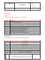
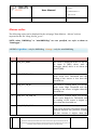
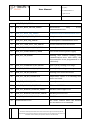
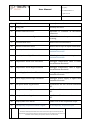
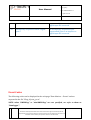
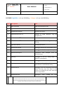
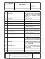
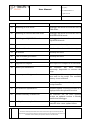
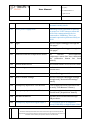
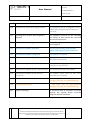
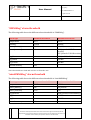
User Manual Rev 2 del 2014/07/09 Copyright © NEXT INDUSTRIES S.r.L All right reserved OMNIAlog and miniOMNIAlog CODE LIST: Errors – Alarms -‐ Events Document owned by Next Industries Srl which reserves the rights sanctioned by the law. Reproductions and partial reproductions of this document can be made only by the issuer. All institutions must to destroy the previous revision of this document. 1 Rev 2 del 2014/07/11 User Manual Copyright © NEXT INDUSTRIES S.r.L All right reserved Error codes OMNIAlog The following error codes are displayed at system startup: Code Description 1 SD Card incorrectly formatted 2 Error formatting SD Card 3 SD Card not found 4 Impossible to access Sensors settings file 5 Impossible to access Communication settings file 6 Impossible to access Datalogger settings file 7 Impossible to access Users settings file 8 Impossible to access Energy Savings settings file 9 Impossible to access Alarms settings file miniOMNIAlog The following error codes are displayed on miniOMNIAlog display: Code Description E0 General Communication or FTP/MAIL connection Error. It refers to log events on web server E1 USB Drive not found. E2 Error in file copy. E3 miniOMNIAlog is already in run mode. E4 It is impossible to start miniOMNIAlog E5 miniOMNIAlog is already in configuration mode. E6 It is impossible to stop miniOMNIAlog. E7 It is impossible to test the modem: it is not present Document owned by Next Industries Srl which reserves the rights sanctioned by the law. Reproductions and partial reproductions of this document can be made only by the issuer. All institutions must to destroy the previous revision of this document. Rev 2 del 2014/07/11 User Manual Copyright © NEXT INDUSTRIES S.r.L All right reserved Alarms codes The following codes can be displayed in the web page “Data Monitor – Alarms” and are exported in the file “ALog_dd_mm_yy.csv”. NOTE: when “OMNIAlog” or “miniOMNIAlog” are not specified, we refer to them as “Datalogger”. LEGEND: Light Blue – only for OMNIAlog Orange – only for miniOMNIAlog Code Description Note 0 eALR_EVT_NONE This event is displayed in the CSV file on the input B (INB) when, with a datalogger alarm, there is no alarm on input B (INB). 1 eALR_EVT_TH_LOW This event is created when you set the alarm event Low Threshold and the reading of the sensor is less than the threshold set. 2 eALR_EVT_TH_HI This event is created when you set the alarm event High Threshold and the reading of the sensor is higher than the threshold set. 3 eALR_EVT_TH_LOW_HI This event is created when you set the alarm event High/Low Threshold and the reading of the sensor is higher or lower than the threshold set. 4 eALR_EVT_TH_DELTA This event is created when you set the alarm event Derivate Threshold and the variation between the previous reading and the current is higher than the Document owned by Next Industries Srl which reserves the rights sanctioned by the law. Reproductions and partial reproductions of this document can be made only by the issuer. All institutions must to destroy the previous revision of this document. Rev 2 del 2014/07/11 User Manual Copyright © NEXT INDUSTRIES S.r.L All right reserved threshold set. 5 eALR_EVT_TH_LOW_DELTA This event is created when you set the alarm event Derivate/Low Threshold and the variation between the previous reading and the current is higher than the threshold set or the reading of the sensor is lower than the lowest threshold set. 6 eALR_EVT_TH_HI_DELTA This event is created when you set the alarm event Derivate/High Threshold and the variation between the previous reading and the current is higher than the threshold set or the reading of the sensor is higher than the highest threshold set. 7 eALR_EVT_TH_LOW_HI_DELTA This event is created when you set the alarm event Derivate/High/Low Threshold and the variation between the previous reading and the current is higher than the threshold set or when the reading of the sensor is higher or lower than the highest or the lowest threshold set. 8 eALR_EVT_COMM This event is created when there is a communication error with a MODBUS device on RS485bus or on electronics dedicated to vibrating wires. 9 eALR_EVT_HW_DL Currently not used. 10 eALR_EVT_CONFIGURATION This event is created when there is a setting error in a sensor that has to be acquired (e.g. sensor is not enabled). 11 eALR_EVT_HW_BASE Currently not used. 12 eALR_EVT_HW_ADC ADC communication error. 13 eALR_EVT_DRDY_ERROR ADC answer error. Document owned by Next Industries Srl which reserves the rights sanctioned by the law. Reproductions and partial reproductions of this document can be made only by the issuer. All institutions must to destroy the previous revision of this document. Rev 2 del 2014/07/11 User Manual Copyright © NEXT INDUSTRIES S.r.L All right reserved 14 eALR_EVT_DAC_ERROR DAC communication error. 15 eALR_EVT_MEAS_DRIVER_ERROR Measurement relay communication error. 16 eALR_EVT_MEAS_SEQ_ERROR SPI measurement communication error. 17 eALR_EVT_MUX_DRIVER_ERROR Multiplexer relay communication error. 18 eALR_EVT_MUX_SEQ_ERROR SPI multiplexer communication error. 19 eALR_EVT_CURR_POLY_FILE_ERROR Current calibration file not found. 20 eALR_EVT_VREF_POLY_FILE_ERROR Currently not used. 21 eALR_EVT_OVERCURRENT_ERROR Overcurrent sensors power supply. 22 eALR_EVT_VW_ERROR Vibrating wire sensors reading error (communication error with dsPIC; the microcontroller is not programmed or it is defective). 23 eALR_EVT_OVERRANGE_INA_ERROR Input A (IN A) reading over range. 24 eALR_EVT_OVERRANGE_INB_ERROR Input B (IN B) reading over range. 25 eALR_EVT_VW_NO_SENSOR Vibrating wire sensor not found. 26 eALR_EVT_VW_NO_TERMISTOR Temperature sensor of a vibrating wire sensor not found. 27 eALR_EVT_MODBUS_BASE Currently not used. 28 eALR_EVT_MODBUS_CRC_ERROR CRC frame MODBUS error. 29 eALR_EVT_MODBUS_FRAMING_ERROR MODBUS frame length error. 30 eALR_EVT_MODBUS_PROTOCOL_ERROR MODBUS protocol error. 31 eALR_EVT_MODBUS_TIMEOUT MODBUS communication timeout. 32 Modem answer error This event created when the modem does not answer to a command. Document owned by Next Industries Srl which reserves the rights sanctioned by the law. Reproductions and partial reproductions of this document can be made only by the issuer. All institutions must to destroy the previous revision of this document. driver Rev 2 del 2014/07/11 User Manual Copyright © NEXT INDUSTRIES S.r.L All right reserved 33 SIM PIN enabled Currently not used. 34 Wrong PIN Currently not used. 35 Modem connection error Impossible to establish an INTERNET connection. 36 Modem connection configuration error INTERNET connection parameters could be wrong. 37 Disconnection error Modem does not disconnect. 38 Inbound connection error Modem can’t accept an input connection. 39 Humidity alarm: Low Threshold OMNIAlog humidity value is lower than minimum threshold. 40 Humidity alarm: High Threshold OMNIAlog humidity value is higher than minimum threshold. 41 Temperature alarm: Low Threshold Datalogger temperature value is lower than minimum threshold. 42 Temperature alarm: High Threshold Datalogger temperature value is higher than minimum threshold. 43 Power Supply alarm: Low Threshold Datalogger power supply is lower than minimum threshold. 44 Power Supply alarm: High Threshold Datalogger power supply is higher than minimum threshold. 45 Low space alarm: Log measure Log Measure file size exceeds maximum size. 46 Low space alarm: Log event Log Events file size exceeds maximum size. 47 Low space alarm: Log alarm Log Alarms file size exceeds maximum size. 48 Script syntax error alarm Syntax error in the acquisition script. 49 Extemporary Acquisition alarm: Digital An extemporary acquisition (not Document owned by Next Industries Srl which reserves the rights sanctioned by the law. Reproductions and partial reproductions of this document can be made only by the issuer. All institutions must to destroy the previous revision of this document. Rev 2 del 2014/07/11 User Manual Copyright © NEXT INDUSTRIES S.r.L All right reserved 50 Input 1 programmed) due to an impulse on digital input IN1 occurred. Extemporary Acquisition alarm: Digital Input 2 An extemporary acquisition (not programmed) due to an impulse on digital input IN2 occurred. Event Codes The following codes can be displayed in the web page “Data Monitor – Events” and are exported in the file “ELog_dd_mm_yy.csv”. NOTE: when “OMNIAlog” or “miniOMNIAlog” are not specified, we refer to them as “Datalogger”. Document owned by Next Industries Srl which reserves the rights sanctioned by the law. Reproductions and partial reproductions of this document can be made only by the issuer. All institutions must to destroy the previous revision of this document. Rev 2 del 2014/07/11 User Manual Copyright © NEXT INDUSTRIES S.r.L All right reserved LEGENDE: Light Blue – solo per OMNIAlog Orange – solo per miniOMNIAlog Code Description Note 0 Login executed Login executed from web. 1 Logout executed Logout executed from web. 2 Configuration Edited Currently not used. 3 Send measures on FTP Attempt to send Measure Log file through FTP. 4 Send events on FTP Currently not used. 5 Send alarms on FTP Attempt to send Alarms Log file through FTP log 6 Login via console Currently not used. 7 Acquisition started Datalogger started the acquisition cycle. 8 Acquisition ended Datalogger ended the acquisition cycle. 9 Acquisition delayed Acquisition start delayed from the scheduled time. 10 Stand-‐by Datalogger is set in “sleep mode” to optimize consumption. 11 Switched on Datalogger has been switched on. 12 Wake up Datalogger woke up from the low-‐power mode to start a scheduled activity . 13 Acquisition set: Datalogger, once an acquisition cycle has ended, sets the next one. After, in the column are displayed the date and time of next acquisition. 14 Acquisition wait Datalogger, after setting the next Document owned by Next Industries Srl which reserves the rights sanctioned by the law. Reproductions and partial reproductions of this document can be made only by the issuer. All institutions must to destroy the previous revision of this document. Rev 2 del 2014/07/11 User Manual Copyright © NEXT INDUSTRIES S.r.L All right reserved acquisition, waits to execute it. 15 Script started: Start executing Script. A script includes an activity that could be executed by Datalogger (e.g. acquisition, control updates, etc.). 16 Script ended Currently not used. 17 Task active Currently not used. 18 Task inactive Currently not used. 19 -‐-‐-‐-‐-‐-‐-‐-‐-‐-‐-‐-‐-‐-‐-‐-‐-‐-‐-‐-‐ Currently not used. 20 email successfully sent The email has been successfully sent to the configured addresses. 21 SMTP server timeout error The SMTP outgoing mail server took too much time to answer or is not available. 22 email sending error It was not possible to send the email to the configured addresses. 23 DNS resolution error The server name resolution gave a negative outcome (it was impossible to reach the server). 24 email connection error It’s not possible to connect to the email server; probably a firewall prevents the connection or the server is not available. 25 mailbox full Datalogger internal email buffer is full. Some emails had been lost since the server is not achievable. 26 DNS resolution ok The server name resolution gave a positive outcome (it was possible to reach the server). 27 Loading error Script The file script is not found on OMNIAlog. 28 Aborted Script The script ended prematurely the Document owned by Next Industries Srl which reserves the rights sanctioned by the law. Reproductions and partial reproductions of this document can be made only by the issuer. All institutions must to destroy the previous revision of this document. Rev 2 del 2014/07/11 User Manual Copyright © NEXT INDUSTRIES S.r.L All right reserved execution. 29 OMNIAlog in STOP mode Datalogger has been set from the user in STOP mode. 30 OMNIAlog in CONFIGURATION mode Datalogger has been set from the user in CONFIGURATION mode 31 OMNIAlog in ACQUISITION mode Datalogger has been set from the user in ACQUISITION mode 32 Syntax error Syntax error in the script. 33 Unbalanced bracket Unbalanced brackets within the script. 34 No formula Currently not used. 35 Is not a variable/procedure Currently not used. 36 Expected: THEN IF structure error. 37 Program too complex The script is too complex to be executed. 38 REPEAT/IF unbalanced The structure has been created incorrectly. Impossible to execute the script. 39 Too many variables/procedures Too many variables or procedures have been used in the script. The available memory is not sufficient. 40 Parameter error An invalid argument had been passed to a script function. 41 New firmware uploaded ver. Firmware update correctly executed. It is displayed also the uploaded version. 42 Firmware already on-‐board ver. The firmware has not been updated because an updated version is already installed on Datalogger 43 BackUp firmware uploaded ver. Datalogger restored the back-‐up firmware after a new update failure. Document owned by Next Industries Srl which reserves the rights sanctioned by the law. Reproductions and partial reproductions of this document can be made only by the issuer. All institutions must to destroy the previous revision of this document. Rev 2 del 2014/07/11 User Manual Copyright © NEXT INDUSTRIES S.r.L All right reserved 44 Restore firmware uploaded Currently not used. 45 FLASH access error! Flash writing error during the firmware upload. 46 BackUp files access error! Backup firmware access error. 47 Restore files access error! Restore firmware access error. 48 BackUp copy error! Backup firmware copy error. 49 New firmware corrupt! The uploading firmware is corrupted and therefore useless. 50 BackUp firmware currupt! The back-‐up firmware on Datalogger is corrupted and therefore useless. 51 Restore firmware currupt! Currently not used. 52 FTP: Authentication error Error in the server FTP access credentials. 53 FTP: File access not possible Impossible to create file on server (verify the path of the destination folder) 54 FTP: File not found The requested file is not on the FTP server (the file with the firmware version for the updates check has not been found on the server). 55 FTP: Generic error FTP generic error 56 FTP: File sending OK The file has been correctly sent from Datalogger to FTP server . 57 FTP: Timeout server FTP server does not answer. 58 FTP: File transfert not possible Error during the connection with FTP server. 59 FTP: Re-‐transmission Overflow queue The re-‐transmission queue is full. 60 SMS sent ok! The SMS has been correctly sent from Datalogger. Document owned by Next Industries Srl which reserves the rights sanctioned by the law. Reproductions and partial reproductions of this document can be made only by the issuer. All institutions must to destroy the previous revision of this document. Rev 2 del 2014/07/11 User Manual Copyright © NEXT INDUSTRIES S.r.L All right reserved 61 SMS sent error! There had been a problem in sending the SMS. 62 PPP Connection Datalogger tries to start an INTERNET connection through GSM/GPRS modem connected to RS-‐232 63 PPP connection established An INTERNET connection through GSM/GPRS modem was established. 64 PPP connection closed INTERNET connection closed. 65 Modem answer error The modem didn’t answer correctly 66 Modem signal level It shows the signal level of the modem 67 No modem signal The modem has no signal 68 Signal level to poor for connection The modem has not enough signal for communication 69 Test modem started Modem test started 70 Log modem info: Generic log on modem 71 OMNIAlog configuration Datalogger is set in CONFIGURATION mode through the web. 72 OMNIAlog stop Datalogger is set in STOP mode through the web. 73 OMNIAlog start Datalogger is started through the web. Document owned by Next Industries Srl which reserves the rights sanctioned by the law. Reproductions and partial reproductions of this document can be made only by the issuer. All institutions must to destroy the previous revision of this document. Rev 2 del 2014/07/11 User Manual Copyright © NEXT INDUSTRIES S.r.L All right reserved 74 Default Calibration: Current Source This event is created when the default calibration file is used. It means that the calibration file created by NEXT INDUSTRIES is incorrectly detected from Datalogger. 75 Default Calibration: Vref This event is created when the default calibration file is used. Vref is not calibrated, so this message could always be used. 76 Default Calibration: 10mV This event is created when the calibration file for the 10mV range is used. It means that the calibration file created by NEXT INDUSTRIES is incorrectly detected from Datalogger. 77 Default Calibration: 100mV This event is created when the calibration file for the 100mV range is used. It means that the calibration file created by NEXT INDUSTRIES is incorrectly detected from Datalogger. 78 Default Calibration: 1V This event is created when the calibration file for the 1V range is used. It means that the calibration file created by NEXT INDUSTRIES is incorrectly detected from Datalogger. 79 Default Calibration: 10V This event is created when the calibration file for the 10V range is used. It means that the calibration file created by NEXT INDUSTRIES is incorrectly detected from Datalogger. 80 Default Calibration: 4-‐20mA This event is created when the calibration file for the 4-‐20mA range is used. It means that the calibration file created by NEXT INDUSTRIES is incorrectly detected from Datalogger. 81 COMX task start Currently not used. Document owned by Next Industries Srl which reserves the rights sanctioned by the law. Reproductions and partial reproductions of this document can be made only by the issuer. All institutions must to destroy the previous revision of this document. Rev 2 del 2014/07/11 User Manual Copyright © NEXT INDUSTRIES S.r.L All right reserved 82 COMX task stop Currently not used. 83 Multiplexer inizialization Currently not used. 84 Multiplexer de-‐inizialization Currently not used. 85 Mailbox allocation failed Task communication error. 86 Internal ADC timeout ADC internal error. 87 web folder updated Web pages update was successful. 88 Restore folder updated The restore folder update was successful. 89 NewFw.hex updated The “NewFw.hex” file has been correctly copied within the “Firmware” folder in the Datalogger SD card. 90 Error during web folder copy Web pages update was unsuccessful. 91 Error during restore folder copy The restore folder update was unsuccessful. 92 Error during NewFw.hex file copy An error occurred during the “NewFw.hex” file copy within the “Firmware” folder on the Datalogger SD card. 93 Bootloader update failed The firmware update through bootloader mode was unsuccessful. 94 OMNIAlog reboot Datalogger has been restarted from the user or after an operation (e.g. data download) that expects a restart. 95 Database update. OMNIAlog configuration After a data structure update, the old deleted. configuration on Datalogger has been deleted to avoid conflicts. 96 Update check error OMNIAlog was not able to check on internet for new firmware. This is an automatic weekly check. 97 Update check executed OMNIAlog successfully checked on Document owned by Next Industries Srl which reserves the rights sanctioned by the law. Reproductions and partial reproductions of this document can be made only by the issuer. All institutions must to destroy the previous revision of this document. Rev 2 del 2014/07/11 User Manual Copyright © NEXT INDUSTRIES S.r.L All right reserved internet for new firmware. This is an automatic weekly check. 98 V OUT power supply reset OMNIAlog resets (switched on and off) the power on V OUT clamp to allow the reset of the communication device connected to OMNIAlog. This is an automatic operation performed daily at 00:00. 99 Login The user logins Datalogger through the Web pages. 100 Logout The user logouts Datalogger through the Web pages. 101 Calibration Internal Temperature Sensor The internal microcontroller temperature sensor has been calibrated (the calibration button has been pushed). 102 External RAM init fail The external RAM is in an incorrect state. 103 Meas. settings; It shows the measure information set from the user. 104 Mod. info: It shows Datalogger model. 105 Reset to default settings The user resets the Datalogger settings through web (“Reset default settings” button). 106 Extemporary Aquisition: Test Measure A test reading has been requested from the web (“Test Measure” button). 107 Extemporary Aquisition: Read Now! A prompt acquisition has been requested from the web (“Acquisition” button). 108 USB Data download Data have been downloaded through USB pen-‐drive. 109 Extemporary Aquisition: Digital Input 1 An acquisition due to an impulsive survey (TRIGGER) on digital input 1 has Document owned by Next Industries Srl which reserves the rights sanctioned by the law. Reproductions and partial reproductions of this document can be made only by the issuer. All institutions must to destroy the previous revision of this document. Rev 2 del 2014/07/11 User Manual Copyright © NEXT INDUSTRIES S.r.L All right reserved been executed. 110 Extemporary Aquisition: Digital Input 2 An acquisition due to an impulse survey (TRIGGER) on digital input 2 has been executed. 111 Vibrating wire search: start frequency adjusted The standard research for the vibrating wire failed. It was started the research on central frequencies. 112 Mail attachment too big The mail attachment was too big and has been dropped. 113 VW firmware update launched The user has already launched DSC update (VW Digital Signal Controller) 114 VW firmware update completed DSC update is complete 115 VW firmware update failed. Timeout DSC DSC update failed because of the timeout (DSC didn’t answered) 116 VW firmware update failed. Verify error DSC update failed (the user can’t correctly set up the DSC) 117 VW firmware update failed. Copy file error DSC update failed (file not found) 118 VW firmware update failed. Hex file corrupted DSC update failed (the file has been found but is corrupted) 119 PC connection established It was established a PC connection through USB (only for miniOMNIAlog) 120 PC connection closed It was done the PC disconnection through USB (only for miniOMNIAlog) 121 System warning 1 An incorrect start of oscillator occurred. Anyway, the system works correctly using the internal oscillator. Document owned by Next Industries Srl which reserves the rights sanctioned by the law. Reproductions and partial reproductions of this document can be made only by the issuer. All institutions must to destroy the previous revision of this document. Rev 2 del 2014/07/11 Copyright © User Manual NEXT INDUSTRIES S.r.L All right reserved “OMNIAlog” alarm threshold The following table shows the different alarm thresholds in “OMNIAlog”. Alarm type Minimum threshold Maximum threshold Temperature -‐20 °C +65 °C Humidity 10,00% 80,00% Power (battery) 25,00% 100,00% Power (external) 9V 20V (up to fw 3.37.17 version) 30V (from fw 3.38.18 version) Log_Measure 10% (so 90% of full memory ) Log_Alarm 100 MB Log_Events 100 MB Internal memory 10% These thresholds are fixed and can’t be set from the user. “miniOMNIAlog” alarm threshold The following table shows the different alarm thresholds in “miniOMNIAlog”. Alarm type Minimum threshold Maximum threshold Temperature -‐20 °C +65 °C Power (battery) 8.4V not present Power (external) 10.5V 14V Log_Measure 10% (so 90% of full memory) Log_Alarm 100 MB Log_Events 100 MB Internal memory 10% Document owned by Next Industries Srl which reserves the rights sanctioned by the law. Reproductions and partial reproductions of this document can be made only by the issuer. All institutions must to destroy the previous revision of this document. User Manual Rev 2 del 2014/07/11 Copyright © NEXT INDUSTRIES S.r.L All right reserved These thresholds are fixed and can’t be set from the user. Document owned by Next Industries Srl which reserves the rights sanctioned by the law. Reproductions and partial reproductions of this document can be made only by the issuer. All institutions must to destroy the previous revision of this document.