1
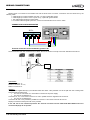
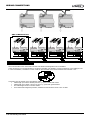
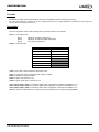
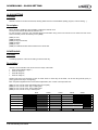
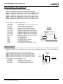
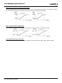
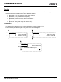
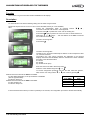
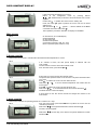
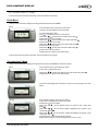
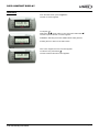
User manual CLIMATIC™ 50 - CHILLERS Providing indoor climate comfort CL50-CHILLERS-IOM_Cust0808-E Climatic 50 CHILLER & HEAT PUMP INCLUDING NEOSYS RANGE USER MANUAL Ref: CL50-CHILLER-IOM_CUST-0808-E CUSTOMER VERSION LENNOX have been providing environmental solutions since 1895, our range of rooftop and chiller continues to meet the standards that have made LENNOX a household name. Flexible design solutions to meet YOUR needs and uncompromising attention to detail. Engineered to last, simple to maintain and Quality that becomes a standard. Further Information on www.lennoxeurope.com. All the technical and technological information contained in this manual, including any drawing and technical descriptions provided by us, remain the property of Lennox and must not be used (except in operation of this product), reproduced, issued to or made available to third parts without the prior written agreement of Lennox. The technical informations and specifications contained in this manual are for reference only. The manufacturer reserves the right to modify these without warning and without obligation to modify equipment already sold. CLIMATIC™50 – Chiller / Heat Pump – Customer version CL50-CHILLER-IOM_CUST-0808-E Page 1 TABLE OF CONTENT Page Introduction.............................................................................................................3 Wiring connections .................................................................................................4 Configuration ..........................................................................................................8 Scheduling – Clock setting .....................................................................................9 Customized input/output.........................................................................................11 Standard input/output .............................................................................................14 Configuration of the BM50 plan address................................................................15 Allocation of displays to the BM50 .........................................................................16 DC50 comfort display .............................................................................................17 DS50 menu tree .....................................................................................................24 Error codes alarms .................................................................................................34 CLIMATIC™50 – Chiller / Heat Pump – Customer version CL50-CHILLER-IOM_CUST-0808-E Page 2 INTRODUCTION CLIMATIC™50 TM The new generation of microprocessor based control, CLIMATIC 50 may be fitted to the Lennox Chiller or Heat pump range. It inherits 20 years of technology and field operating experience from its predecessors the TM TM CLIMATIC 1 and CLIMATIC 2. LENNOX has found the latest hardware technology available on the market place and developed software specifically designed for Chiller and Heat pump applications, maximising the LENNOX unit’s efficiency and performance. Compatibility This documentation is compatible with the programs Chiller and Heat pump: NEOSYS range from software version NA050.01. Warning Any parameter modification should be carried out by trained and licensed competent technician. Before start-up or restart of a unit controlled by Climatic 50, it is mandatory to check adequacy TM between Climatic 50 and the unit with its options. Menus (38xx) for unit and options, Menus (39xx) for communication. In case of wrong parameters, I/O links could be incorrect and may create some operation problems for the units and ultimately breakdowns. Lennox cannot be held responsible for any claims on the units due to a wrong parameters sequence or a parameters modification carried out by non competent technicians. In this case, the warranty will be legally null and void. CLIMATIC™50 – Chiller / Heat Pump – Customer version CL50-CHILLER-IOM_CUST-0808-E Page 3 WIRING CONNECTIONS IMPORTANT WARNING Any wiring modification on the CLIMATIC™50 must be done by Lennox technician or employees having valid electrical qualification and authorisation. For any modification of wiring on the 24V supply or on 4-20mA sensor, check the polarity prior to apply the power. Wrong polarity may cause serious damage and destroy the pLAN network. Lennox will not accept liability for damage caused by wrong power connection or any wiring modification done by people without valid training and qualifications. Any external connection with the unit, using 24Vac voltage should not exceed a length of more than 30m. It concerns external contacts connected to Climatic™50 on logical inputs. Over 30 m, the installer must interface this information with relays or converters. In any case, the 24Vac control voltage must not be used to drive external function with Climatic™50 logical output. WARNING: Separate as much as possible probes, displays, logical input cables from power cables with strong inductive load, in order to avoid possible electromagnetic perturbations. CONNECTION SENSORS AND PROBES External sensors or probes connection must be carried out with the following cable: o Cable length up to 20m: AWG22 (0.34 mm ²), 1 pair crossed with screen. o Cable length up to 50m: LiYCY-P (0.34 mm ²), 1 pair with general shield. The cable length should not exceed 50m. For a better electromagnetic protection, Lennox recommends the use of LiYCY-P cable. DISPLAY DS50 The Display DS50 can be connected to the Climatic™50 either on one of the RJ12 connectors located on the board DT50, or directly on the main board BM50 connector J10. Connection is carried out by the flat 1.5m cable delivered with this DS50. In any the case, Display DS50 cannot be remotely connected. In case of Master/Slave installation, one, and only one, display DS50 must be connected on the pLan bus. DISPLAY DC50 (Remote CONNECTION) Warning: A wrong wiring of the display immediately damage it and/or the main board BM50. The optional DC50 is designed to be mounted on the wall. Fit the cable from the DT50 board through the back piece Fasten the back piece to the wall using the rounded head screws supplied in the packaging Connect the cable from the main board on the connector on the back of the DC50 display Fasten the front panel on the back piece using the flush head screws supplied Finally fit the click-on frame CLIMATIC™50 – Chiller / Heat Pump – Customer version CL50-CHILLER-IOM_CUST-0808-E Page 4 WIRING CONNECTIONS Display DC50 is connected to the Climatic™50 with the DT50 screw connector. Connection must be carried out by the following cable: Cable length up to 300m: AWG22 (0.34 mm ²), 2 pairs crossed with screen. Cable length up to 500m: LiYCY-P (0.34 mm ²), 2 pairs with general shield. The cable length should not exceed 500m. For a better electromagnetic protection, Lennox recommends the use of LiYCY-P cable. CONNECTION ON DT50 DERIVATOR DT50 DC50 3 + 4 GND VL 2 1 1 2 3 4 Terminal connection board installation guide DT 50 The board is fitted with three "telephone" RJ12 plugs. Ensure the board is correctly connected. Standard connection is: Ferrite Connectors: BM50 on connector 'C’, DC50 on connector ‘A’ or ‘C’, DS50 on connector ‘B’. Jumpers: "Displays" are supplied directly by the Climatic board with 30Vdc. Take particular care at the path this 30V is taking when several boards are being used. J14 and J15 can switch on or off the direct current from the power supply: J14 and J15 set between1-2: Connectors ‘A’, ‘B’, ‘C’ and screw connector ‘SC’ are in parallel. Power is supplied to all connectors. J14 and J15 set between2-3: Connectors ‘B’ and ‘C’ are powered in parallel but connector ‘A’ and screw connector SC are not. Displays connected to these ports will not be powered. If J14 and J15 are set in different positions the "terminal connection board" DT50 DOES NOT WORK and so the connected displays do not operate. CLIMATIC™50 – Chiller / Heat Pump – Customer version CL50-CHILLER-IOM_CUST-0808-E Page 5 WIRING CONNECTIONS Ferrites Protection of Display To avoid the appearance of disturbances HF, which can cause the destruction of components in the displays, you must equip the cable with a ferrite when installing it (provided by Lennox). FERRITE N°1 Remote DC50 DT50 BM50 FERRITE N°2 COMMUNICATION MASTER / SLAVE The intercard bus (pLan) is connected to Climatic™50 on the J11 connector of board BM50. A star connection is not recommended, for an optimum operation it is advised to connect a maximum of two cables per unit. Connection must be carried out by the following cable: Cable length up to 300m: AWG22 (0.34 mm ²), 2 pairs crossed with screen. Cable length up to 500m: LiYCY-P (0.34 mm ²), 2 pairs with general shield. The cable length should not exceed 500m. For a better electromagnetic protection, Lennox recommends the use of LiYCY-P cable. Warning: The power 24Vac of boards BM50 should not be connected to the earth. CLIMATIC™50 – Chiller / Heat Pump – Customer version CL50-CHILLER-IOM_CUST-0808-E Page 6 WIRING CONNECTIONS BMS COMMUNICATION The communication bus is connected to Climatic™50 Serial Card daughter board on the BM50. A star connection is not recommended, for an optimum operation it is advised to connect a maximum of two cables per unit. In case of RS485bus, a resistance of 120Ω 1/4W can be connected on the last unit between the terminals + and -. Connection must be carried out by the following cable: Cable length up to 300m: AWG22 (0.34 mm ²), 2 pairs crossed with screen. Cable length up to 1000m: LiYCY-P (0.34 mm ²), 2 pairs with general shield. The cable length should not exceed 1000m. For a better electromagnetic protection, LENNOX recommends the use of LiYCY-P cable. CLIMATIC™50 – Chiller / Heat Pump – Customer version CL50-CHILLER-IOM_CUST-0808-E Page 7 CONFIGURATION Function LENNOX© proposes a parametric designed software for the NEOSYS chillers & Heat pumps ranges. For a first use, before any operation of the unit, Climatic™50 must be set with parameters in accordance to the range, the size and the various options of the unit. Description The unit configuration is done with following menus (refer also to Menu Tree chapter): (3811) Unit range choice, [NAC] [NAH] [NSR] NEOSYS, air/water (cooling only), NEOSYS, air/water reversible (heat pump), Non standard request unit. (3812) Unit size choice, NAC NAC 200 STD NAH NAH 200 STD NAC 230 STD NAH 230 STD NAC 270 STD NAH 270 STD NAC 300 STD NAH 300 STD NAC 340 STD NAC 380 STD NAC 420 STD NAC 480 STD (3813) Unit with or without Electronic Expansion valve, (3821) Evaporator pumps configuration (No, single or double), (3822) Installation glycol percentage, (3823) Option free Cooling or not, (3824) Option heat recovery or not, (3825) Option power factor correction or not, (3831), (3832), (3833), (3834) Parametric digital output configuration of extension board BE50 1 to 4, (3841), (3842), (3843), (3844) Parametric digital input configuration of extension board BE50 1 to 4, (3851), (3852), (3853), (3854) Parametric analog input configuration of extension board BE50 1 to 4, (3861) Restore the standard Lennox settings or not (This parameter don’t modify the settings (38xx), CLIMATIC™50 – Chiller / Heat Pump – Customer version CL50-CHILLER-IOM_CUST-0808-E Page 8 SCHEDULING – CLOCK SETTING CLOCK SETTING Function Climatic™50 has a real time clock board, allowing dates and hours functionalities (weekly program, event recording,…). Description Menus (3121) to (3125) give the possibility of setting the internal clock. The day of the week is calculated by Climatic™50. For the countries of the Euro, the controller allows the automatic swing of the hour summer in hour winter and vice versa. This functionality can be cancelled by menu (3126). (3121) Hour, (3122) Minute, (3123) Day of the month, (3124) Month, (3125) Year, (3126) Enable automatic switch summer time / winter time. SCHEDULING Function Controlling operation of the unit according to the time and day. Description Climatic™50 can handle 4 time zones over the 7 days of the week: Zone unoccupied « Night », Zone A «Day A», Zone B «Day B», Zone C «Day C», Starting time (hours and minutes) of each of these zones for each days of the week, can be set using menus (3211) to (3214), (press ‘PRG key to change day). Each set point integrates the hour and minute’s adjustment, thus a value of 8.3 equal 8.30 a.m. (3211) Hour, minute of the night starting time (unoccupied) (3212) Hour, minute of the “day A” starting time (3213) Hour, minute of the “day B” starting time (3214) Hour, minute of “day C” starting time 8h00 Monday Unoccupied 12h00 Z :A 13h50 Z :B 20h30 Z :C 22h00 Unoccupied Tuesday Wednesday Thursday Friday Saturday Sunday CLIMATIC™50 – Chiller / Heat Pump – Customer version CL50-CHILLER-IOM_CUST-0808-E Page 9 SCHEDULING – CLOCK SETTING For each time zone, the set following set points following can be modified: Code DISPLAY CONFORT DISPLAY MAINTENANCE (3311) Yes Yes Cooling Water T° Set point A (3321) Yes Yes Cooling Water T° Set point B (3322) Yes Yes Cooling Air Ambient T° Set point A (3323) Yes Yes Cooling Air Ambient T° Set point B (3324) Yes Yes Heating Water T° Set point A (3331) Yes Yes Heating Water T° Set point B (3332) Yes Yes Heating Air Ambient T° Set point A (3333) Yes Yes Heating Air Ambient T° Set point B (3334) Yes Yes Enable compressor on circuit N°1 (3411) Yes Yes Enable compressor on circuit N°2 (3412) Yes Yes Fan Mode Set point (3611) Yes Yes Low Noise Value Set point (3612) Yes Yes (3711) Yes Yes LIST SET POINT BY ZONE Change over control Cooling / Heating priority Water temperature Compressor enable Fan condensing Cooling water pump(s) Enable pump(s) Programming Beginning of zone; each day Yes Yes Start Uno (3211) Yes Yes Start z.A (3212) Yes Yes Start z.B (3213) Yes Yes Start z.C (3214) Yes Yes With the DS50, for each set point, press on the key `PRG to change the periods and to validate the good set point for the good zone. Note: “Monday” is considered as the first day of the week for programming the CLIMATIC™50. Factory settings: “Day A” activated from Monday to Saturday 6h22h Night mode (unoccupied) for the remaining of time, Sunday included CLIMATIC™50 – Chiller / Heat Pump – Customer version CL50-CHILLER-IOM_CUST-0808-E Page 10 CUSTOMIZED INPUT/OUTPUT Function The Climactic™50 main board (BM.50) and the optional expansion board (BE.50) offers possibilities to customize some input / output for remote control of the unit. So it is possible to customize: 5 digital outputs NC or NO set up with parameters (3841), (3842), (3843) and (3845), 6 digitals inputs set up by parameters (3851), (3852), (3853) and (3854), 4 analogical inputs (4-20mA or Lennox NTC temperature probe), set up with parameters (3861), (3862), (3863) and (3864). Description The wiring connection between the BM.50 and the BE.50 is described on the following figure: Power Supply 6 7 BM.50 tLAN(+) tLAN(-) BE.50 BE.50 The various possibilities of customized inputs / outputs functions can be configured as follow: Please, respect the wiring connections warning before connect the free input/output. (cf. “WIRING CONNECTIONS” section). DIGITAL OUTPUTS NC or NO – DRY CONTACTS Electrical characteristics: Maximum commutable power: 2000VA, 250Vac. The corresponding between the connectors and the settings is: (3831) Setting for the digital output on the connector BE50-J5-NO1, (3832) Setting for the digital output on the connector BE50-J6-NO2, (3833) Setting for the digital output on the connector BE50-J7-NO3, (3834) Setting for the digital output on the connector BE50-J8-NO4. The following items can be used for each output: [Not Used.] Contact not used, [C.1 Alarm] Alarm on circuit N°1, [C.2 Alarm] Alarm on circuit N°2, [Fans Al.] Alarm on the condensing fan, [Pump Al.] Alarm on the pump, [Flow Al.] Alarm on the flow rate, [Heat. Mode] Unit operating in heating mode (Reversible unit only), [C.1 100%] Circuit N°1 running at full load (compressors), [C.2 100%] Circuit N°2 running at full load (compressors), [U. 100%] Unit running at full load (Circuits N°1&2), [U. On] Unit ready to start, [Z:A] Unit operating Zone A, [Z:B] Unit operating Zone B, [Z:C] Unit operating Zone C, [Uno] Unit operating Zone Unoccupied, [Bms] Unit operating Zone BMS, [Free] Free for BMS acting, [Elec.H.] Electrical heaters (up to 4) (Reversible unit only). CLIMATIC™50 – Chiller / Heat Pump – Customer version CL50-CHILLER-IOM_CUST-0808-E Free Dry Contact Example BE50-J5.NO1 Page 11 CUSTOMIZED INPUT/OUTPUT DIGITAL INPUTS – DRY CONTACTS Electrical characteristics: 24Vac or 24Vdc, 50/60Hz. The corresponding between the connectors and the settings is: (3841) Setting for the digital output on the connector BM50-J8-ID13, (3842) Setting for the digital output on the connector BM50-J8-ID14, (3843) Setting for the digital output on the connector BE50-J4-ID1, (3844) Setting for the digital output on the connector BE50-J4-ID2, (3845) Setting for the digital output on the connector BE50-J4-ID3, (3846) Setting for the digital output on the connector BE50-J4-ID4. The following items can be used for each input: [Not Used] Input not used, [Sw Setpoint] Switch to the second cooling / heating set point, [Sw Cool.] Switch the unit to the cooling mode, [Sw Heat.] Switch the unit to the heating mode, [C1 Disable] Disable the circuit N°1 (all compressors), [C2 Disable] Disable the circuit N°2 (all compressors), [Circ.1-Cp.1] Disable the compressor N°1 on the circuit N°1, [Circ.1-Cp.2] Disable the compressor N°2 on the circuit N°1, [Circ.1-Cp.3] Disable the compressor N°3 on the circuit N°1, [Circ.2-Cp.1] Disable the compressor N°1 on the circuit N°2, [Circ.2-Cp.2] Disable the compressor N°2 on the circuit N°2, [Circ.2-Cp.3] Disable the compressor N°3 on the circuit N°2, [Z:A] Unit operating Zone A, [Z:B] Unit operating Zone B, [Z:C] Unit operating Zone C, [Uno] Unit operating Zone Unoccupied, [Bms] Unit operating Zone BMS, [Free] Free for BMS system information, [Elec.H.] Electrical heaters fault (Reversible unit only). Example BE50-J4.ID1 6 7 Free Dry Contact ANALOG INPUTS Electrical characteristics: The analog input on the same connector J9 (B1 and B2) must use the same type of signal (4/20mA or NTC). As well, the analog input on the same connector J10 (B3 and B4) must use the same type of signal (4/20mA or NTC). The corresponding between the connectors and the settings is: (3851) Setting for the analog input on the connector BE50-J9-B1, (3852) Setting for the analog input on the connector BE50-J9-B2, (3853) Setting for the analog input on the connector BE50-J10-B3, (3854) Setting for the analog input on the connector BE50-J10-B4. The following items can be used for each input: [Not Used] Not used, [S.P Water] Water set point 4-20mA signal, [S.P Offset] Water set point offset 4-20mA signal, [Free NTC] Free temperature probe connection. CLIMATIC™50 – Chiller / Heat Pump – Customer version CL50-CHILLER-IOM_CUST-0808-E NTC Probe 4/20mA Signal - + Example BE50-J9.B1, BE50-J9.B2 Page 12 CUSTOMIZED INPUT/OUTPUT Water set point cooling / heating 4-20mA signal: The 4-20mA signal sent to the unit is linearly converted using the 2 water temperature set points. To increase the precision, you can customize 2 range of water set point according to the cooling or heating mode operating. Water set point offset 4-20mA signal: The 4-20mA signal sent to the unit is linearly converted using a -5K to +5K range of temperature set point. Free temperature probe connection: Lennox NTC sensor: The measured value will be displayed on following addresses (2171), (2172), (2173) or (2174). CLIMATIC™50 – Chiller / Heat Pump – Customer version CL50-CHILLER-IOM_CUST-0808-E Page 13 STANDARD INPUT/OUTPUT Function The Climactic™50 main board (BM.50) offers free dry contacts to control the unit. These free dry contacts are connected directly to terminals (orange colour) identified as follow: [824 - 825] : 24V relay customers power supply (Option), [826 - 827] : 24V power ON the unit (Option), [804 - 805] : Remote alarm reset (NC = Enable Reset), [808 - 809] : Water evaporator customer flow switch, [890 - 891] : Remote ON / OFF of the unit. [870 – 871 - 872] : Alarm relay (NC = Alarm OFF). Connection The following figure described how to connect the free dry contacts of Climactic™50. For the contacts [824 - 825] and [826 - 827], refers to the electrical diagram. 890 891 Remote ON / OFF Open = Unit OFF Closed = Unit ON 804 805 808 809 Water Evaporator Flow Switch Open = Flow OFF Closed = Flow ON Remote Reset Alarm Open = Reset OFF Closed = Reset ON The reset is enable only on a positive front edge of the signal ( ). CLIMATIC™50 – Chiller / Heat Pump – Customer version CL50-CHILLER-IOM_CUST-0808-E Page 14 CONFIGURATION OF THE BM50 pLAN ADDRESS Function It may be necessary to change the address of the BM50 card on the pLan network – mainly in the case of Master/Slave installation. To do this, use the following procedure: Description Set the address of the DS/DC50 display to 0: Sds.1 Access the configuration mode by pressing the buttons , for at least 5 seconds until the Sds.1 screen appears: Press button to position the cursor over the ‘Setting’ line With the or button, set the address of the display to 00 (instead of the standard value of 32) and confirm with button Sds.2 The Sds.2 screen appears. Changing the address of BM50 Sds.3 Switch the power supply to the BM50 card off, then on again after 5 seconds. When the Sds.3 screen appears, press, the ‘Alarm’ and buttons for 5 seconds. Sds.4 The Sds.4 screen appears. Press the button to position the cursor over the ‘pLan address’ line. With button or set the desired pLan address (1 to 12) and confirm with button . CLIMATIC™50 – Chiller / Heat Pump – Customer version CL50-CHILLER-IOM_CUST-0808-E Page 15 ALLOCATION OF DISPLAYS TO THE BM50 Function Ensure there is a good connection between the BM50 and its displays Description For each Climatic™50 card the following setting must be made using the DS50. Disconnect the pLan bus at J10 and J11 and connect the DS50, directly to J10 of the BM50; Sds.1 Access the configuration mode by pressing buttons , for at least 5 seconds until the Sds.1 screen appears: Press the button to position the cursor over the ‘Setting’ line Press button again to position the cursor over the ‘I/O board adress’ line With button or replace ‘- -‘ with the address of the BM50 connected and confirmed with button Sds.5 Sds.6 (for the DC50) The Sds.5 screen appears. Press button The Sds.6 screen appears. The field "P:XX " shows the selected pLan address. In this example the value "01" has been selected. The fields in the "Adr" column represent the addresses of the terminal displays associated with this BM50, while the "Priv/Shared" column indicates the status of the selected terminal. Pr: Private Sh: Shared Sp: Shared Printer (N/A) Move the cursor from field to field using button Select the value desired using button or. To exit the configuration procedure and save the data, select the "OK?No", field, choose "Yes" using buttons or and confirm by pressing Trm1 is reserved to allocate the DC50 to the BM50. Its value differs depending on the pLan address of the BM50 (See the opposite table) Its status is always ‘Pr’ Trm3 is reserved to allocate the DS50 to the BM50. Its value is always 32 Its status is always ‘Sh’ pLan address of the BM50 1 2 3 4 Trm1 DC50 17 pr 18 pr 19 pr 20 pr If the terminal remains inactive (no button is pressed) for 30 seconds, the configuration procedure is aborted automatically. CLIMATIC™50 – Chiller / Heat Pump – Customer version CL50-CHILLER-IOM_CUST-0808-E Page 16 DC50 COMFORT DISPLAY Function This display is connected remotely; it is intended for users with no technical knowledge. This display gives access to general operating data of the unit. It does not give access to detailed operating data. It can be used to set or change the programming of the various time periods and the temperature set point for each period. It also has the ability to set a 3 hours override and force an unoccupied mode, or any other different time periods, for a maximum of 7 days. It displays a real time clock and the various fault signals. Buttons ‘Prg’ Access set points ‘Up’ Access overrides or increase values ‘Clock Access the clock ‘Enter’, Confirms the selection ‘Esc’ Return to the previous display ‘Down’ Access overrides or decrease values Brightness/Contrast The display has a set contrast, but this can be adjusted manually. For manual adjustment of the contrast, press the ‘Prg’ and ‘Clock buttons simultaneously and press buttons or to increase or reduce the contrast. Configuration of the terminal address Sdc.1 The address of the terminal DC50 must be checked after having switching on the card. Access the configuration mode by pressing buttons simultaneously for at least 5 seconds, until the Sdc.1 screen appears. Press the ‘Enter’ buttonto position the cursor over the ‘Setting’ line With button or set the address of the display. See table below for the DC50, then confirm with button pLan address with BM50 connected 1 2 3 4 CLIMATIC™50 – Chiller / Heat Pump – Customer version CL50-CHILLER-IOM_CUST-0808-E DC50 Address 17 (local display) 21 (remote display) 18 (local display) 22 (remote display) 19 (local display) 23 (remote display) 20 (local display) 24 (remote display) Page 17 DC50 COMFORT DISPLAY Sdc.2 The Sdc.2 screen appears. If after 5 seconds the display is not correct; Return to the configuration mode by pressing buttons simultaneously for at least 5 seconds until the Sdc.1 screen appears. Press button to position the cursor over the ‘Setting’ line Press, the button again to position the cursor over the ‘I/O board address’ line With the button or replace ‘- -‘ with the address of the BM50 connected and confirm with button Then repeat the procedure “Allocation of Displays to the BM50” Main screen Sdc.3 On the first line, as a double display: Outlet temperature On the second line: Outside air temperature Current time period (Z:A, Z:B, Z:C, Uno) Mode of operation (Heat, Dead or Cool) 3 Hours override This function can be used to override either the desired outlet temperature for 3 hours. Sdc.3 If an override is active, the time period display is alterned with the ‘Ove’ symbol. The ‘Esc’ button is used to cancel the override mode. From the main screen, press button or Sdc.4 Screen Sdc.4 is used to change the override values The present time period is shown on the 2nd line. This period will remain fixed for 3 hours. Press to position the cursor over the ‘Water SP’ line With button or to set the desired temperature and confirm with the ‘Enter’ button. Press to position the cursor over the ‘Mode SP’ line With button or to set the desired mode and confirm with button The DC50 returns to the main display. A single press on the ‘Esc’ button cancels the changes and returns to the main screen. 1 week override This function overrides the operating periods for a maximum of 7 days. Sdc.5 From the Sdc.3 screen, press button twice to position the cursor over the ‘Override a period’ line With button or set the period desired and confirm with button . The Sdc.5 screen appears. With button or with button . CLIMATIC™50 – Chiller / Heat Pump – Customer version CL50-CHILLER-IOM_CUST-0808-E set the days of the week to the period desired and confirm Page 18 DC50 COMFORT DISPLAY In this example, the unit will remain in the unoccupied period on Tuesday when confirmed until midnight on Thursday. It will revert back to the main screen after 15 seconds without any activity. Clock Menu These screens are used to display and change the time and date on the BM50. Sdc.6 From the main screen, press the ‘clock’ button The Sdc.6 screen displays the time and date. To change the time or date: Press to position the cursor over the time. With button or set the time and confirm with button Position the cursor over ‘minutes’. With button or set the minutes and confirm with button Position the cursor over ‘month’. With button or set the month and confirm with button Position the cursor over ‘year’. With button or set the year and confirm with button Position the cursor over ‘hours’. Pressing the ‘Esc’ returns to the main screen It will revert back to the main screen after 15 seconds without any activity. “Programming” Menu These screens are used to display and change the set points of the BM50 for each time period. Sdc.7 From the main screen, press the "Prg" button, Screen Sdc.7 displays the menu. With button or to select the “Setting” item and confirm with button . Pressing the ‘Esc’ returns to the main screen. Sdc.8 The next screen display the unit status for each zone by pressing on the "Clk" button. Sdc.9.a From the Sdc.8 screen; press the ‘Prg’ button Screen Sdc.9.a displays the change over mode. Position the cursor over “Mode” With button or set the desired mode for period A and confirm with button . With button or set the winter outside temperature the period A and confirm with button . With button or set the summer outside temperature the period A and confirm with button . Press the button ‘Clk’ to change the time period. Repeat the procedure for each time period (Z:A, Z:B, Z:C, Uno). CLIMATIC™50 – Chiller / Heat Pump – Customer version CL50-CHILLER-IOM_CUST-0808-E Page 19 DC50 COMFORT DISPLAY CLIMATIC™50 – Chiller / Heat Pump – Customer version CL50-CHILLER-IOM_CUST-0808-E Page 20 DC50 COMFORT DISPLAY Sdc.9.b From the Sdc.9.a screen; press the ‘Prg’ button Screen Sdc.9.b displays the water set points. With button or set the desired temperature for period A and confirm with button . Press the button ‘Clk’ to change the time period. Repeat the procedure for each time period (Z:A, Z:B, Z:C, Uno). Sdc.9.c From the Sdc.9.b screen; press the ‘Prg’ button Screen Sdc.9.b displays the period settings. Position the cursor over period A With button or set the start time for period A and confirm with button . Position the cursor over period B. With button or set the start time for period B and confirm with button . Position the cursor over period C. With button or set the start time for period C and confirm with button . Position the cursor over the Uno period. With button or set the unoccupied period and confirm with button . Position the cursor over period A. Pressing the ‘Esc’ returns to the main screen. Select the day of the week by repeatedly pressing the ‘Clock’ button It will revert back to the main screen after 15 seconds without any activity. Major Alarm Sdc.10 In the event of activation of a fault on the unit, screen Sdc.10 is displayed. Button ‘Prg’ is illuminated. All buttons are deactivated The only way to regain control of the DC50 is to resolve the fault on the unit. To display the alarm history of the unit, press button Sdc.11 The history can store the last 32 alarms occurring on the unit. Each alarm is memorised at the date and time of occurrence of the fault. An active alarm is signified by the symbol ‘’. An acknowledged alarm is signified by the symbol ‘=’. Each alarm is signified by a 3 digit code (see ERROR CODES ALARMS section) Sdc.12 Press the ‘Alarm’ button to reset all the alarms, if possible The number of active alarms returns to 0, no active alarm is shown in the menu, and the ‘Alarm’ button is no longer illuminated. To highlight the title of the error code, position the cursor over the line desired with buttons or , then confirm with the ‘Enter’ button Use the ‘Esc’ button to return to the previous levels. CLIMATIC™50 – Chiller / Heat Pump – Customer version CL50-CHILLER-IOM_CUST-0808-E Page 21 DC50 COMFORT DISPLAY Start/stop Sdc.13 Sdc.14 From the main screen, press the button The Sdc.13 screen appears. To stop the unit: With button or set the value to ‘Yes’ and confirm with button The unit stops and the Sdc.14 screen appears WARNING: Switching off the unit disables all the safety devices Pressing the ‘Esc’ returns to the main screen. Sdc.15 If the unit is stopped, the Sdc.15 screen appears. To start the unit, press button The unit starts and the main screen appears. CLIMATIC™50 – Chiller / Heat Pump – Customer version CL50-CHILLER-IOM_CUST-0808-E Page 22 DC50 COMFORT DISPLAY Navigation in the screens Main menu (0000) S.5 The four digits in brackets indicate the number of the current menu. The two digits beside the brackets indicate the pLan number of the selected card. The display on the right indicates the period of operation and the current time conditions. S.6 Scrolling the menus Press button or to move the cursor upwards or downwards. The item selected is displayed in CAPITAL letters preceded by the symbol ‘’. It can then be selected by pressing button . A ‘+’ or ‘++’ symbol beside the number of the first or third line indicates the existence of one or more additional lines. Menu Data (2000) S.7 Example: S.5 to S.9 show how the menu tree changes each time button from the menu is pressed Data (2000) General (2100) Temperature (2110) (2111) Outside temperature 16.0°C (2112) Inlet temperature 12.0°C (2113) Outlet temperature 07.0°C Press “Esc” at any time sends to return to the previous level of the menu tree. In the example shown above, “Esc” must be pressed 3 times to return to the main menu (0000) S.8 S.9 CLIMATIC™50 – Chiller / Heat Pump – Customer version CL50-CHILLER-IOM_CUST-0808-E Page 23 DS50 MENU TREE Menu Item Menu Item Menu Item Menu 1000 2000 ALARM DATA 2100 GENERAL 2110 TEMPERATURE 2120 CIRCUIT 1 2130 CIRCUIT 2 2140 OTHER 2150 OUT CUSTOM 2160 IN CUSTOM 2170 IN % CUSTOM 2210 COOL WATER 2220 HEAT WATER 2310 CIRC.1.COMP.1 2320 CIRC.1.COMP.2 2111 2112 2113 2114 2121 2122 2123 2124 2125 2126 2127 2128 2131 2132 2133 2134 2135 2136 2137 2138 2141 2142 2143 2144 2151 2152 2153 2154 2161 2162 2163 2164 2165 2166 2171 2172 2173 2174 2211 2212 2213 2214 2221 2222 2223 2224 2311 2312 2313 2314 2315 2316 2317 2318 2321 2200 2300 CONTROL COMPRESSOR CLIMATIC™50 – Chiller / Heat Pump – Customer version CL50-CHILLER-IOM_CUST-0808-E Item OUTSIDE INLET OFFSET OUTSIDE T°SUPERHEAT T°COND T°SATU T°SUCT P.COND P.SATU T°DISCH.11 T°DISCH.12 T°SUPERHEAT T°COND T°SATU T°SUCT P.COND P.SATU T°DISCH.21 T°DISCH.22 SW ON/OFF SW FLOW SW RESET SW INOC BE50.1 BE50.2 BE50.3 BE50.4 BM50.1 BM50.2 BE50.1 BE50.2 BE50.3 BE50.4 BE50.1 BE50.2 BE50.3 BE50.4 RSP COOL CAPA.COOL OFFSET SW 2° SP RSP HEAT CAPA.HEAT OFFSET SW 2° SP CONFIG. STATUS SW STATE SW RELAY SW HP SW LP VALVE RUN TIME CONFIG. UNIT MIN MAX FACTORY °C °C °C °C °C °C °C °C Bar Bar °C °C °C °C °C °C Bar Bar °C °C OFF/ON OFF/ON OFF/ON OFF/ON OFF/ON OFF/ON OFF/ON OFF/ON OFF/ON OFF/ON OFF/ON OFF/ON OFF/ON OFF/ON °C / mA '°C / mA '°C / mA '°C / mA °C % °C OFF/ON °C % °C OFF/ON List List OFF/ON OFF/ON OFF/ON OFF/ON OFF/ON Hour List Page 24 DS50 MENU TREE Menu Item Menu 2400 2500 Item EEV FAN Menu Item 2330 CIRC.1.COMP.3 2340 CIRC.2.COMP.1 2350 CIRC.2.COMP.2 2360 CIRC.2.COMP.3 2410 CIRCUIT 1 2420 CIRCUIT 2 2510 CIRCUIT 1 CLIMATIC™50 – Chiller / Heat Pump – Customer version CL50-CHILLER-IOM_CUST-0808-E Menu Item 2322 2323 2324 2325 2326 2327 2328 2331 2332 2333 2334 2335 2336 2337 2338 2341 2342 2343 2344 2345 2346 2347 2348 2351 2352 2353 2354 2355 2356 2357 2358 2361 2362 2363 2364 2365 2366 2367 2368 2411 2412 2413 2421 2422 2423 2511 2512 2513 2514 2515 2516 2517 STATUS SW STATE SW RELAY SW HP SW LP VALVE RUN TIME CONFIG. STATUS SW STATE SW RELAY SW HP SW LP VALVE RUN TIME CONFIG. STATUS SW STATE SW RELAY SW HP SW LP VALVE RUN TIME CONFIG. STATUS SW STATE SW RELAY SW HP SW LP VALVE RUN TIME CONFIG. STATUS SW STATE SW RELAY SW HP SW LP VALVE RUN TIME CONFIG. STATUS POSITION CONFIG. STATUS POSITION CONFIG. STATUS SW STATE MODE VALUE MAXIMUM CAPACITY UNIT MIN MAX FACTORY List OFF/ON OFF/ON OFF/ON OFF/ON OFF/ON Hour List List OFF/ON OFF/ON OFF/ON OFF/ON OFF/ON Hour List List OFF/ON OFF/ON OFF/ON OFF/ON OFF/ON Hour List List OFF/ON OFF/ON OFF/ON OFF/ON OFF/ON Hour List List OFF/ON OFF/ON OFF/ON OFF/ON OFF/ON Hour List OFF/ON --List OFF/ON --List List OFF/ON List °C % % Page 25 DS50 MENU TREE Menu Item Menu 2600 Item OPTION Menu Item Menu 2520 CIRCUIT 2 2610 COOL PUMP 2521 2522 2523 2524 2525 2526 2527 2611 2612 2613 2614 2615 2616 2617 2618 CLIMATIC™50 – Chiller / Heat Pump – Customer version CL50-CHILLER-IOM_CUST-0808-E Item CONFIG. STATUS SW STATE MODE VALUE MAXIMUM CAPACITY CONFIG. STATUS 1 STATUS 2 SW STATE SW RELAY 1 SW RELAY 2 RUN TIME 1 RUN TIME 2 UNIT MIN MAX FACTORY List List OFF/ON List °C % % List List List OFF/ON OFF/ON OFF/ON H H Page 26 BMS ADDRESS TABLES ModBus, Trend, BACnet & Carel LOGICAL DATA 01H 1 R/W 0/1 02H 2 R/W 0/1 03H 3 R/W 0/1 04H 4 R/W 0/1 05H 5 R/W 0/1 06H 6 R 0/1 Description [On/Off] General On/Off of the unit [Off] Unit OFF - [On] Unit ON [Reset] Discharges the safety measures of the unit [BMS] BMS On/Off of the unit [Off] Unit OFF - [On] Unit ON not used [BMS] Activation of the Inoccupation mode : [Off] Occupation mode - [On] Inoccupation mode not used 07H 7 R 0/1 not used 08H 8 R 0/1 not used 09H 9 R 0/1 not used 0AH 10 R 0/1 not used 0BH 11 R 0/1 not used 0CH 12 R 0/1 not used 0DH 13 R 0/1 not used 0EH 14 R 0/1 not used 0FH 15 R 0/1 10H 16 R/W 0/1 11H 17 R 0/1 not used [Clock] Read / Update the internal clock board of the BM50 [OFF] Read hour & minute - [ON] Write hour & minute not used 12H 18 R/W 0/1 [Dry contact] Digital Output, Free 1, BE50-J5-NO1 2151 13H 19 R/W 0/1 [Dry contact] Digital Output, Free 2, BE50-J6-NO2 2152 14H 20 R/W 0/1 [Dry contact] Digital Output, Free 3, BE50-J7-NO3 2153 15H 21 R/W 0/1 [Dry contact] Digital Output, Free 4, BE50-J8-NO4 2154 16H 22 R 0/1 not used 17H 23 R 0/1 not used 18H 24 R 0/1 not used 19H 25 R 0/1 not used 1AH 26 R 0/1 not used 1BH 27 R 0/1 not used 1CH 28 R 0/1 not used 1DH 29 R 0/1 not used 1EH 30 R 0/1 not used 1FH 31 R 0/1 not used 20H 32 R 0/1 not used 21H 33 R 0/1 [Alarm] General alarm 22H 34 R 0/1 [On/Off] Pump, 1 2615 23H 35 R 0/1 [On/Off] Pump, 2 2616 24H 36 R 0/1 [On/Off] Compressor 1, Circuit 1 2316 25H 37 R 0/1 [On/Off] Compressor 2, Circuit 1 2326 @ (hexa) @ (deci) R/W Unit CLIMATIC™50 – Chiller / Heat Pump – Customer version CL50-CHILLER-IOM_CUST-0808-E DS50 3111 3113 3112 BMS 3925 Unoc … Page 27 BMS ADDRESS TABLES 26H 38 R 0/1 [On/Off] Compressor 3, Circuit 1 2336 27H 39 R 0/1 [On/Off] Compressor, Heat pump, Circuit 1 2317 28H 40 R 0/1 [On/Off] Compressor 1, Circuit 2 2346 29H 41 R 0/1 [On/Off] Compressor 2, Circuit 2 2356 2AH 42 R 0/1 [On/Off] Compressor 3, Circuit 2 2366 2BH 43 R 0/1 [On/Off] Compressor, Heat pump, Circuit 2 2347 2CH 44 R 0/1 not used 2DH 45 R 0/1 not used 2EH 46 R 0/1 not used 2FH 47 R 0/1 not used 30H 48 R 0/1 not used 31H 49 R 0/1 [Dry contact] Digital Input, Free 1, BM50-J8-ID13 2161 32H 50 R 0/1 [Dry contact] Digital Input, Free 2, BM50-J8-ID14 2162 33H 51 R 0/1 [Dry contact] Digital Input, Free 1, BE50-J4-ID1 2163 34H 52 R 0/1 [Dry contact] Digital Input, Free 2, BE50-J4-ID2 2164 35H 53 R 0/1 [Dry contact] Digital Input, Free 3, BE50-J4-ID3 2165 36H 54 R 0/1 [Dry contact] Digital Input, Free 4, BE50-J4-ID4 2166 37H 55 R 0/1 38H 56 R 0/1 39H 57 R 0/1 3AH 58 R 0/1 3BH 59 R 0/1 3CH 60 R 0/1 3DH 61 R 0/1 3EH 62 R 0/1 [Water] Cool Mode Operating 3FH 63 R 0/1 not used 40H 64 R 0/1 [Water] Heat Mode Operating CLIMATIC™50 – Chiller / Heat Pump – Customer version CL50-CHILLER-IOM_CUST-0808-E Page 28 BMS ADDRESS TABLES ANALOGIC DATA Description [ BMS ] Activation of the control by a computer or an automat. Mode BMS is activated if this value is different from zero. This value is decreased every second. [Unit] without pump: 0=Started; 1=Stopped [Unit] with pump: 1=Stopped; 2:P1 Only; 3=P2 Only; 4=P1-N P2-S; 5=P2-N P1-S; 6=P1/P2 by clock DS50 1=1 [Unit] Change-over: 0=Cool. Only; 1=Heat. Only; 2=Auto. Pump; 3=Auto. No Pump 3311 BMS R 1=1 not used 5 R/W 10 = 1.0°c [Occupation][Water SP] Required water temperature in °C Cooling set point. 3321 BMS 06H 6 R/W 10 = 1.0°c [Occupation][Water SP] Required water temperature in °C Heating set point. 3331 BMS 07H 7 R/W 10 = 1.0°c [Inoccupation][Water SP] Required water temperature in °C Cooling set point. 3321 Uno 08H 8 R/W 10 = 1.0°c [Inoccupation][Water SP] Required water temperature in °C Heating set point. 3331 Uno 09H 9 R not used 0AH 10 R not used 0BH 11 R not used 0CH 12 R/W 1 = 1h [Clock] Hour 3121 0DH 13 R/W 1 = 1m [Clock] Minute 3122 0EH 14 R/W 1=1 [Clock] Day of the month 3123 0FH 15 R/W 1=1 [Clock] Month 3124 10H 16 R/W 1 = 2001 [Clock] Year 3125 11H 17 R/W 10 = 1.0°c 12H 18 R/W 13H 19 R/W 14H 20 R/W not used 15H 21 R/W not used 16H 22 R/W not used 17H 23 R/W not used 18H 24 R/W not used 19H 25 R/W not used 1AH 26 R/W not used 1BH 27 R/W not used 1CH 28 R/W not used 1DH 29 R/W not used 1EH 30 R/W not used 1FH 31 R/W not used 20H 32 R/W not used 21H 33 R 1=1 22H 34 R 10 = 1.0°c [Temperature] Inlet, Water 2112 23H 35 R 10 = 1.0°c [Temperature] Outdoor, Air 2111 @ (hexa) @ (deci) R/W Unit 01H 1 R/W 1=1s 02H 2 R/W 1=1 03H 3 R/W 04H 4 05H 3934 3711 BMS [BMS] Outlet temperature coming from the BMS. not used 10 = 1.0°c CLIMATIC™50 – Chiller / Heat Pump – Customer version CL50-CHILLER-IOM_CUST-0808-E [BMS] Outdoor temperature coming from the BMS. [Alarm] Code Error … Page 29 BMS ADDRESS TABLES 24H 36 R 10 = 1.0°c [Temperature] Outlet, Water 2113 25H 37 R 10 = 1.0b [Temperature] High, Circuit 1 2122 26H 38 R 10 = 1.0b [Temperature] Low, Circuit 1 2123 27H 39 R 10 = 1.0b [Temperature] High, Circuit 2 2132 28H 40 R 10 = 1.0b [Temperature] Low, Circuit 2 2133 29H 41 R 10 = 1.0b [EEV] Saturated evaporation temperature, Circuit 1 2124 2AH 42 R 10 = 1.0b [EEV] Saturated evaporation temperature, Circuit 2 2134 2BH 43 R 10 = 1.0b not used 2CH 44 R 10 = 1.0b not used 2DH 45 R 1 = 1% [% of opening] Fan, Modulation, Circuit 1 2517 2EH 46 R 1 = 1% [% of opening] Fan, Modulation, Circuit 2 2527 2FH 47 R 1 = 1% not used 30H 48 R 1 = 1% not used 31H 49 R 10 = 1.0°c [Temperature] Temperature, Free 1, BE50-J9-B1 2171 32H 50 R 10 = 1.0°c [Temperature] Temperature, Free 2, BE50-J9-B2 2172 33H 51 R 10 = 1.0°c [Temperature] Temperature, Free 3, BE50-J10-B3 2173 34H 52 R 10 = 1.0°c [Temperature] Temperature, Free 4, BE50-J10-B4 2174 35H 53 R 1=1 not used 36H 54 R 1=1 not used 37H 55 R 1=1 not used 38H 56 R 1=1 not used 39H 57 R 10 = 1.0°c [EEV] Current superheating value, Circuit 1 2121 3AH 58 R 10 = 1.0°c [EEV] Current superheating value, Circuit 2 2131 3BH 59 R 10 = 1.0°c not used 3CH 60 R 10 = 1.0°c not used 3DH 61 R 10 = 1.0°c not used 3EH 62 R 10 = 1.0°c not used CLIMATIC™50 – Chiller / Heat Pump – Customer version CL50-CHILLER-IOM_CUST-0808-E Page 30 BMS ADDRESS TABLES 3FH 63 R 10 = 1.0 40H 64 R 10 = 1.0 CLIMATIC™50 – Chiller / Heat Pump – Customer version CL50-CHILLER-IOM_CUST-0808-E [Alarm] bit.0 = Flow switch bit.1 = High Temperature, Outlet bit.2 = Low Temperature, Inlet bit.3 = Low Temperature, Outlet bit.4 = High Temperature, Inlet bit.5 = Pump, 1 bit.6 = Pump, 2 bit.7 = Real Time Clock bit.8 = BE50 bit.9 = not used bit.10 = Probes & Sensors bit.11 = Fans, Condenser, Circuit 1 bit.12 = Fans, Condenser, Circuit 2 bit.13 = Fans, Condenser, Circuit 3 bit.14 = not used bit.15 = not used [Alarm] bit.0 = Compressor, Circuit 1, Electric Protection bit.1 = Compressor, Circuit 1, High Pressure bit.2 = Compressor, Circuit 1, Low Pressure or Freeze protection bit.3 = Compressor, Circuit 2, Electric Protection bit.4 = Compressor, Circuit 2, High Pressure bit.5 = Compressor, Circuit 2, Low Pressure or Freeze protection bit.6 = not used bit.7 = not used bit.8 = not used bit.9 = not used bit.10 = not used bit.11 = not used bit.12 = Compressor, Circuit 1, Electronic Expansion Valve bit.13 = Compressor, Circuit 2, Electronic Expansion Valve bit.14 = not used bit.15 = not used Page 31 BMS ADDRESS TABLES LonWorks LOGICAL DATA Type BM50 Index DGT 1 I_Sp_On_Unit 95 input 415 DGT 1 O_Sp_On_Unit 95 output 415 DGT 2 I_Sp_Reset 95 input 416 DGT 2 O_Sp_Reset 95 output 416 DGT 3 I_Sp_Unoc 95 input 417 DGT 3 O_Sp_Unoc 95 output DGT 17 O_Od_Alarm 95 DGT 18 O_Od_Pump_1 95 DGT 19 O_Od_Pump_2 DGT 20 DGT 21 DGT Name NV Type NV Direction Index Description DS50 [On / Off] Unit 3111 [Reset] Discharges the safety measures of the unit 3113 [BMS] Activation of the Inoccupation mode [Off] occupation mode - [On] inoccupation mode 3925 417 output 431 [Alarm] General 1000 output 432 [On/Off] Pump, 1 2615 95 output 433 [On/Off] Pump, 2 2616 O_Od_Comp_11 95 output 434 [On/Off] Compressor 1, Circuit 1 2316 O_Od_Comp_21 95 output 435 [On/Off] Compressor 2, Circuit 1 2326 22 O_Od_Comp_13 95 output 436 [On/Off] Compressor 3, Circuit 1 2336 DGT 23 O_Od_CompHPump_1 95 output 437 [On/Off] Compressor, Heat pump, Circuit 1 2317 DGT 24 O_Od_Comp_12 95 output 438 [On/Off] Compressor 1, Circuit 2 2346 DGT 25 O_Od_Comp_22 95 output 439 [On/Off] Compressor 2, Circuit 2 2356 DGT 26 O_Od_Comp_23 95 output 440 [On/Off] Compressor 3, Circuit 2 2366 DGT 27 O_Od_CompHPump_2 95 output 441 [On/Off] Compressor, Heat pump, Circuit 2 2347 DGT 28 not used 95 output 442 not used DGT 29 not used 95 output 443 not used DGT 30 not used 95 output 444 not used DGT 31 not used 95 output 445 not used ANALOGIC DATA Type BM50 Index ANL 1 I_Sp_WCool_1_BMS 105 input 1 ANL 1 O_Sp_WCool_1_BMS 105 output 1 ANL 2 I_Sp_WHeat_1_BMS 105 input 2 ANL 2 O_Sp_WHeat_1_BMS 105 output 2 ANL 3 I_Sp_WCool_1_Uno 105 input 3 ANL 3 O_Sp_WCool_1_Uno 105 output 3 ANL 4 I_Sp_WHeat_1_Uno 105 input 4 ANL 4 O_Sp_WHeat_1_Uno 105 output ANL 17 O_Ia_TEEG 105 ANL 18 O_T_Outside 105 ANL 19 O_Ia_TSEG ANL 20 O_Ia_P_HP_1 ANL 21 O_Ia_P_BP_1 ANL 22 ANL 23 ANL Name NV Type NV Direction Index Description DS50 [Occupation][Water SP] Required water temperature in °C Cooling set point 3321 BMS [Occupation][Water SP] Required water temperature in °C Heating set point 3331 BMS [Inoccupation][Water SP] Required water temperature in °C Cooling set point 3321 Uno 4 [Inoccupation][Water SP] Required water temperature in °C Heating set point 3331 Uno output 17 [Temperature] Inlet, Water 2112 output 18 [Temperature] Outdoor, Air 2111 105 output 19 [Temperature] Outlet, Water 2113 105 output 20 [Pressure] High, Circuit 1 (Bar) 2125 105 output 21 [Pressure] Low, Circuit 1 (Bar) 2126 O_Ia_P_HP_2 105 output 22 [Pressure] High, Circuit 2 (Bar) 2135 O_Ia_P_BP_2 105 output 23 [Pressure] Low, Circuit 2 (Bar) 2136 24 not used 105 output 24 not used ANL 25 not used 105 output 25 not used ANL 26 not used 105 output 26 not used ANL 27 not used 105 output 27 not used CLIMATIC™50 – Chiller / Heat Pump – Customer version CL50-CHILLER-IOM_CUST-0808-E Page 32 BMS ADDRESS TABLES INTEGER DATA Type Index Name NV Type NV Direction Index Description [ BMS ] Activation of the control by a computer or an automat - mode BMS is activated if this value is different from zero, This value is decreased every second [Unit] without pump: 0=Started; 1=Stopped [Unit] with pump: 1=Stopped; 2:P1 Only; 3=P2 Only; 4=P1N P2-S; 5=P2-N P1-S; 6=P1/P2 by clock INT 1 I_Sp_BMS_Dog 8 input 208 INT 1 O_Sp_BMS_Dog 8 output 208 INT 2 I_Sp_RunUnit_BMS 8 input 209 INT 2 O_Sp_RunUnit_BMS 8 output 209 INT 3 I_Sp_ChOver_BMS 8 input 210 INT 3 O_Sp_ChOver_BMS 8 output 210 INT 4 I_Sp_Rotat_BMS 8 input 211 INT 4 O_Sp_Rotat_BMS 8 output 211 [Unit] Activation of the circuits: 0=C1 Only; 1=C2 Only; 2=C1/C2 by clock INT 17 O_Error_Codes 8 output 224 [Alarm] Code Error INT 18 not used 81 output 225 not used INT 19 not used 81 output 226 not used INT 20 not used 81 output 227 not used INT 21 not used 81 output 228 INT 22 O_Error_Bits_1 8 output 229 INT 23 O_Error_Bits_2 8 output 230 not used [Alarm] bit.0 = Flow switch bit.1 = High Temperature, Outlet bit.2 = Low Temperature, Inlet bit.3 = Low Temperature, Outlet bit.4 = High Temperature, Inlet bit.5 = Pump, 1 bit.6 = Pump, 2 bit.7 = Real Time Clock bit.8 = BE50 bit.9 = not used bit.10 = Probes & Sensors bit.11 = Fans, Condenser, Circuit 1 bit.12 = Fans, Condenser, Circuit 2 bit.13 = Fans, Condenser, Circuit 3 bit.14 = not used bit.15 = not used [Alarm] bit.0 = Compressor, Circuit 1, Electric Protection bit.1 = Compressor, Circuit 1, High Pressure bit.2 = Compressor, Circuit 1, Low Pressure or Freeze protection bit.3 = Compressor, Circuit 2, Electric Protection bit.4 = Compressor, Circuit 2, High Pressure bit.5 = Compressor, Circuit 2, Low Pressure or Freeze protection bit.6 = not used bit.7 = not used bit.8 = not used bit.9 = not used bit.10 = not used bit.11 = not used bit.12 = Compressor, Circuit 1, Electronic Expansion Valve bit.13 = Compressor, Circuit 2, Electronic Expansion Valve bit.14 = not used bit.15 = not used CLIMATIC™50 – Chiller / Heat Pump – Customer version CL50-CHILLER-IOM_CUST-0808-E [Unit] Change-over: 0=Cool. Only; 1=Heat. Only; 2=Auto. Pump; 3=Auto. No Pump DS50 3934 3711 (BMS) 3311 BMS 3411 (BMS) 1000 Page 33 ERROR CODES ALARMS 001 011 012 013 022 023 040 041 042 070 071 081 083 085 086 087 092 093 094 108 111 112 114 115 117 118 121 122 124 125 127 128 210 211 214 215 216 217 219 220 221 224 225 226 227 228 Flow Rate Water Evaporator Electrical Heater(s) High Outlet Water Temperature Low Inlet Water Temperature Low Outlet Water Temperature High Inlet Water Temperature Pump Flow Pump 1 Pump 2 Clock card BE50 Temperature Probe Water Inlet Temperature Probe Outside Temperature Probe Water Outlet Temperature Probe Water Heat Recovery Inlet Temperature Probe Water Heat Recovery Outlet Circuit 1 Condenser fan Circuit 2 Condenser fan Circuit 3 Condenser fan Correction Power factor Circuit 1 Probe High Pressure Circuit 1 Probe Low Pressure Circuit 1 Compressor(s) Circuit 1 High pressure Circuit 1 Low pressure Circuit 1 Risk of Frosting Circuit 2 Probe High Pressure Circuit 2 Probe Low Pressure Circuit 2 Compressor(s) Circuit 2 High pressure Circuit 2 Low pressure Circuit 2 Risk of Frosting Circuit 1 EEV Driver Circuit 1 EEV Low Superheat Temperature Circuit 1 EEV L.O.P Circuit 1 EEV Valve NOT Closed Circuit 1 EEV Probe Low Pressure or Suction Temperature Circuit 1 EEV Motor Circuit 1 EEV Battery Circuit 2 EEV Driver Circuit 2 EEV Low Superheat Temperature Circuit 2 EEV L.O.P Circuit 2 EEV Valve NOT Closed Circuit 2 EEV Probe Low Pressure or Suction Temperature Circuit 2 EEV Motor Circuit 2 EEV E.E.P.R.O.M CLIMATIC™50 – Chiller / Heat Pump – Customer version CL50-CHILLER-IOM_CUST-0808-E Page 34 www.lennoxeurope.com BELGIUM, LUXEMBOURG www.lennoxbelgium.com PORTUGAL www.lennoxportugal.com Due to Lennox’s ongoing commitment to quality, the Specifications, Ratings and Dimensions are subject to change without notice and without incurring liability. CZECH REPUBLIC www.lennox.cz RUSSIA www.lennoxrussia.com Improper installation, adjustment, alteration, service or maintenance can cause property damage or personal injury. Installation and service must be performed by a FRANCE www.lennoxfrance.com SLOVAKIA www.lennoxdistribution.com GERMANY www.lennoxdeutschland.com SPAIN www.lennoxspain.com GREAT BRITAIN www.lennoxuk.com UKRAINE www.lennoxrussia.com NETHERLANDS www.lennoxnederland.com OTHER COUNTRIES www.lennoxdistribution.com POLAND www.lennoxpolska.com CL50-CHILLERS-IOM_Cust0808-E qualified installer and servicing agency.