1
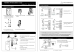
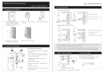
SCR100 User Manual Version:1.1 Date:Dec 2009 Introduction: This document mainly introduces the installations and connections of SCR100 products, and the brief operations about attendance software. Important Claim Firstly thank you for purchasing our products. Before use, please read this manual carefully to avoid the unnecessary damage! The company reminds you that the proper user will improve the use affect and authentication speed. No written consent by our company, any unit or individual isn’t allowed to excerpt, copy the content of this manual in part or in full, also spread in any form. The product described in the manual maybe includes the software which copyrights are shared by the licensors including ZKSoftware Inc. Except for the permission of the relevant holder, any person can’t copy, distribute, revise, modify, extract, decompile, disassemble, decrypt, reverse engineering, leasing, transfer, sub-license the software, other acts of copyright infringement, but the limitations applied to the law is excluded. Due to the constant renewal of products, the company can not undertake the actual product in consistence with the information in the document, also any dispute caused by the difference between the actual technical parameters and the information in this document. Please forgive any change without notice. Contents 1. Must Know .........................................................................................3 1.1 Product profile............................................................................................ 3 1.2 Front View.................................................................................................. 3 1.3 Installation Precautions .............................................................................. 4 1.4 Schematic Diagram for System Installation ............................................... 7 1.5 Schematic Diagram for Communication Connections................................ 8 2. Installation..........................................................................................9 2.1 Fix the plate................................................................................................ 9 2.2 Connecting Peripherals............................................................................. 10 2.2.1 Door Sensor Cables.......................................................................11 2.2.2 Exit Switch Cables ....................................................................... 12 2.2.3 Alarm Cables................................................................................ 12 2.2.4 Electronic Lock Cables ................................................................ 13 2.2.5 Ethernet Cables ............................................................................ 17 2.2.6 RS232 Cables............................................................................... 18 2.2.7 RS485 Cables............................................................................... 19 2.2.8 Wiegand Output Cables................................................................ 20 2.2.9 Power Cables................................................................................ 21 2.3 Fastening the Device ................................................................................ 22 2.4 Inspection after Installation ...................................................................... 22 3. Attendance Software ......................................................................23 3.1 Register a device ...................................................................................... 23 3.2 Register a User and an ID card................................................................. 25 3.3 Upload and download............................................................................... 27 3.3.1 Upload to device .......................................................................... 27 3.3.2 Download to PC ........................................................................... 29 3.4 Monitor in real time.................................................................................. 29 4. Others ................................................................................................31 4.1 Reset Button ............................................................................................. 31 4.2 Tamper Switch.......................................................................................... 32 1. Must Know 1.1 Product Profile SCR100 released by our company is the World’s first access controller and reader based on TCP/IP, professional access control machine with RF card but no screen and no press-key. These access control product series added with RF card provide a more product choices for system access control solutions. It can be used as a separate control locks, also can be used as an access controller connecting RF cards, to realized master-slave machine or anti-pass back function. Standard TCP/IP protocol can realize connection and networking crossover network and gateway. It can be embedded with Webserver to visit query records and so on via Internet. 1.2 Front View LED indicator 1. When the device is in verifying status, LED indicator light is blue and flashes once per 2 seconds. When the device is in enrollment and deletion status, LED indicator light is off. 2. If a successful verification, enrollment or deletion, LED indicator light is green and constant on for 1 second. If a failed verification, enrollment or deletion, LED indicator light is red and constant on for 1 second. -3- 3. When the door is opened normally, if the device detects the door is not closed well after the time of “door sensor delay time” (which can be set by the suited access control software), the buzzer will long ring, if device detects the door is still not closed well after a minute long ring, the device will issue the alarm signal. Note:If the prompts of both device’s LED indicator light and buzzer are different from the above, please contact the relevant technicians. 1.3 Installation Precautions Although our products are manufactured in accordance with the stringent manufacturing and inspection standards specified by China, USA and EU, we still recommend you to read the Installation Precautions carefully before installation. We recommend you to use this product properly so as to greatly improve the recognition performance and speed. Failure to read the Installation Precautions carefully before installation may result in serious accidental damage to the product due to improper installation. Therefore, to avoid unnecessary equipment damage, please do read the Installation precautions carefully before installation. 1. Ensure the power system is switched off prior to installation because live-line operation is quite hazardous and may result in the damage of the equipment and even core components due to power cable contact. 2. The stripped (naked) ends of all wiring terminals shall not be in excess of 5 mm to avoid equipment damage due to accidental contact with the naked ends. Furthermore, connection cables in -4- 3. 4. 5. 6. 7. 8. different colors must be adopted. Connect the grounding cable first in places with large static electricity or in winter before connecting other cables to avoid equipment damage due to instant excessive static electricity. Connect power cables only after connecting all the other cables. If the product cannot operate properly, please perform necessary inspection after cutting off the main power supply. Do keep in mind that all live-line operations may result in accidental equipment damage and our warranty does not cover any equipment damage arising out of such operations. Only test the exit switch only when you have assigned other personnel outside of the door after the installation because you may be unable to exit the door due to accidental problems. Our equipment provides a self-test function for you to perform self-test after installation to confirm whether the installation is complete. It is recommended to adopt the 12V DC power supply with current larger than 3A. It is recommended to use 12V DC electronic locks with current less than 1.5A. Consult related technical personnel if the power parameters of the locks exceed the specified range. The current of the power supply shall be at least 1A larger than that of the electronic locks. Failure to meet the above power supply requirement may possibly lead to electronic lock drive failure or even equipment damage. Before connecting cables for equipment, please read and follow the instructions in the Installation Guide. The burnout of core boards due to improper cable connection and equipment start failure due to fingerprint sensor burnout both fall beyond our warranty scope. -5- 9. If the distance between the power supply and equipment is large, do not replace power cables with network cables or other types of cables. When selecting power cables, take into account the voltage attenuation caused by long transmission distance. 10. When adopting the RS485 networking mode, use dedicated RS485 cables and active RS232/485 converter, and distribute cables by adopting the bus structure. If the RS485 communication distance is over 100m, the RS485 bus must be terminated using termination resistors with impedance of about 120Ω at both ends of the network. For matters not mentioned herein, see User Manual, Software Instructions and Appendix. -6- 1.4 Schematic Diagram for System Installation -7- 1.5 Schematic Diagram for Communication Connections 1. The device directly connects with the computer. TCP/IP or RS232 PC SCR100 0 2. The device connects to the computer over an RS485 network. RS485 bus RS485 converter PC … RS232 3. The device connects to the computer over an Ethernet. Switch PC TCP/IP … TCP/IP TCP/IP -8- 2. Installation 2.1 Fix the plate 1) Post the mounting template on the wall. Drill holes according to the marks on the template.(Holes for screw and wiring) 3) Take away the screw on the bottom of device。 2) Take off the water-proof cushion 4) Release the mounting plate 5) Fix the cushion and plate on the wall -9- 2.2 Connecting Peripherals Ensure the power supply is cut off before cable connection. Live-line cable connection may result in serious damage to the equipment. Connect the following peripherals in the sequence presented below: 1) Door sensor cables (Sensor, GND) 2) Exit switch cables (Button, GND) 3) Alarm cables (Alarm+, Alarm-) 4) Electronic lock cables (NC, COM, NO) 5) Ethernet cables (RJ45-1, RJ45-2, RJ45-3, RJ45-4) 6) RS232 cables (232RX, 232TX, GND) 7) RS485 cables (485A, 485B) 8) Wiegand output cables (WD0, WD1, GND) 9) Wired door bell (Bell+, Bell-) 10)Power cables (GND, +12V) -10- 2.2.1 Door Sensor Cables The door sensor is used to sense the door open/close status. The device generates an alarm when sensing that there is an unauthorized entry or the door is not closed within the specified time through the door sensor. -11- 2.2.2 Exit Switch Cables The exit switch is a door access device installed inside the room. To open the door, press the pushbutton exit switch. The exit switch is installed about 1400 mm above the floor. Ensure the exit switch is well aligned without skew and cables are properly connected and fastened. (Cut the naked ends of unused cables and wrap them with insulating tape) Take measures against the electromagnetic interference (EMI). (For example, lighting switches and computers) 2.2.3 Alarm Cables The alarm output of access control machine is a switch signal,it can be connected to the circuit of simple alarm in serial, it can also be used as a signal to trigger the advanced alarm/monitor system. (This alarm output can only support 12VDC alarm) -12- 2.2.4 Electronic Lock Cables The installations of the door locks are subject to the types of locks used. When selecting the power cables of an electronic lock, you need to take into account the internal resistance on the transmission lines. Ensure the electronic lock is securely fastened and cables are properly connected. For electric bolt locks and electromagnetic locks, do not reverse the positive (+) and negative (-) terminals. Cut the naked ends of unused cables on locks and wrap them separately with insulating tape. The operation latency of an electric bolt lock can be adjusted as required. The device supports the NO and NC electronic locks concurrently as long as they are connected to different terminals. NC: The circuit-breaker is closed in normal conditions. When the device is opened by force, the circuit is opened, thus resulting in the status change. NO: The circuit-breaker is opened in normal conditions. When the device is closed by force, the circuit is closed, thus resulting in the status change. Power Ground (GND): Power loop grounding wire connector. In practice, various types of electronic locks are in use, and therefore the proper cable connection methods must be subject to the lock specifications. Note: The door lock is controlled by a lock relay. When installing a lock, you need to take into account two factors: safety and security, that is, what do you expect from a door during a power outage? To keep “Safety During Power Outage” or “Security During Power Outage”? “Safety During Power Outage”: In the event of a power outage (possibly because of the cutting-off of the power supply or the controller -13- failure), the door is automatically opened for free entry and exit and only locked after the power returns. Such a type of door ensures access to the protected areas in the event of emergencies. A typical application of this mechanism is the use of electromagnetic locks. The locks can only be opened when the power supply is normal. “Security During Power Outage”: Doors adopting this mechanism ensure the protected areas are still under protection at all events. A typical application of this mechanism is the use of electronic locks which can only be opened from within in the event of a power outage. You can decide the power supply mode when installing locks based on the following calculation: The operating voltage of the device is 12V. In the following expressions, I is defined as the current input by the power supply; ULock is defined as the operating voltage of the lock; ILock is defined as the operating current of the lock. 1. The device shares power supply with the electronic lock, as shown in Figure 1 and Figure 2: 1) ULock=12V, I-ILock>1A; 2) The distance between the electronic lock and the device is short. 2. The device and the electronic lock adopt separate power supply, as shown in Figure 3 and Figure 4: 1) ULock=12V, I-ILock≤1A; 2) ULock≠12V; 3) The distance between the electronic lock and the device is long. -14- Figure 1 NC electronic lock (sharing power supply with the device) Figure 2 NO electronic lock (sharing power supply with the device) -15- Figure 3 NC electronic lock (adopting an independent power supply) Figure 4 NO electronic lock (adopting an independent power supply) Note: To prevent the self-induced Electromotive Force (EMF) generated when an electronic lock is opened/closed from impacting the access control system, connect in parallel a diode FR107 (do not reverse the -16- positive (+) and negative (-) terminals) on the electronic lock to discharge the self-induced EMF when connecting cables for the access control system on site. 2.2.5 Ethernet Cables The background PC software can communicate with the device, upload and download data and perform remote management of the terminal over TCP/IP. The device can connect with Ethernet in the following two ways: 1) The device connects with a computer through a crossover cable. IP:192.168.1.201 Subnet mask:255.255.255.0 PC 2) The device and computers form a Local Area Network (LAN) through network cables and a hub. PC Switch -17- 2.2.6 RS232 Cables The background software can communicate with the device through RS232 to upload and download data. Definition for connections between PC and device PC Serial Port Device Serial Port RXD TXD TXD RXD GND GND Schematic diagram of cable connection PC Serial port -18- 2.2.7 RS485 Cables Cables must be distributed by adopting the bus structure in RS485 networking mode. The RS485 communication cable consists of a shielded twisted pair. The RS485 transfers signals through the voltage difference between two communication cables. The differential-mode interference will be generated between two signal cables during signal transfer. A bias resistor (termination resistor) can be added in the circuit to eliminate the differential-mode interference. Generally the termination resistor is not required. The RS485 bus must be terminated using termination resistors with impedance of about 120Ω at both ends of the network only when the RS485 communication distance is over 100m. Definition of terminal connection Number of Terminals Function 485+ RS-485 communication + 485- RS-485 communication RS485Bus PC PC RS485 Converter … RS232 -19- 2.2.8 Wiegand Output Cables The device provides standard Wiegand26 output. It can connect to a majority of access controllers, just like connecting an IC card reader or an encryption keyboard. It is recommended that the cable between the device and controller is not over 90m in length. (The wiegand signal extender can be adopted in cases where long transmission distance is required or the interference nearby is quite strong.) Note: 1) The device and the access controller or card reader must share a common ground regardless of whether they share the power supply or not, so as to ensure Wiegand signal stability. 2) If Wiegand output or RS485 communication distance is over 90m, it is recommended to adopt shielded cables and connect them to the SGND terminal to avoid interference caused by long-distance transmission. -20- 2.2.9 Power Cables The operating voltage of the device is 12V DC, the operating current is about 500mA, and the standby current is about 50mA. Connect the device to the power supply through the power wiring terminals. You can also adopt the standard delivery-attached power adapter, with connection methods shown in the following two figures. 1. Connect the positive (+) and negative (-) terminals of power supply directly to +12V and GND. (Do not reverse the positive (+) and negative (-) terminals) 2. Insert the plug of the 12V power adapter into the power socket. 2PIN Power Socket -21- 2.3 Fastening the Device 1) 2) 3) 4) Ensure all cables are properly connected. Attach the device to the rear wall-mount plate (From the top down) to place it flat against the wall-mount plate, as shown in Figure ①. Fasten the device to the rear wall-mount plate by using a screw, as shown in Figure ②. Ensure the device is securely fastened after installation. Figure ① Figure ② 2.4 Inspection after Installation After the whole system installation is complete, check whether the system is properly installed prior to power-on. Check whether the lock drive and other devices operate properly. The green indicator will start blinking upon power-on. -22- 3. Attendance Software Suppose the device has connected with PC well and the attendance software has been installed already, on the desktop, click “Start” “Programs” “Fingerprint Access Control & Time Attendance System” to enter into the main window as shown below: The following briefly describes the co-operations between device and software. For details, please refer to “Access Control Software User Manual.” 3.1 Register a device 1) Register a device for the first time. In the main window of Access Control & Time Attendance Software, click the button “Device Manage” in tool bar to pop up the window as shown below: -23- 2) In IP address column, input the device’s IP address 192.168.1.201 (default address) and click the button “Test Connect”. When connecting to device successfully, the message box “Succeed in connecting with device” will be popped up. Click the button “OK” to close the message box. 3) One PC can connect with multiple devices, and the attendance software in PC can manage multiple devices at the same time. If you want to add devices, please click the button “Add”. If you want to delete devices, select devices and click the button “Delete”. For details, please refer to “Access control software user manual”. -24- 3.2 Register a User and an ID card 1) Register a user. In the main window of Access Control & Time Attendance Software, click the button “User Manage” in toolbar to pop up the window as shown below. In this window, click the button “ add a user and input the relevant user information. ” to 2) Select a registered device. Firstly select a registered device in the left framework and then click the button “Connect Device”. If a successful connection, the button “Connect Device” will be changed to the button “Disconnect”. -25- 3) Enroll an ID card for a user. Click the button “input card” and then punch an ID card on the device. If the card is punched successfully, the card number will be displayed in Card number column. 4) Save a user. After enrolling, click the button “ add the user into the user list. -26- ” to save and 5) Delete a user. In the user list, select the user you want to delete and then press the button “ ” to delete. The deleted user here is the user in software but not the user in device. If you want to delete users in device, please refer to the down 3.3. Upload and download. 3.3 Upload and download For a PC corresponding to multiple devices, the user information in PC can be uploaded to multiple devices, and user information in multiple devices can be downloaded to this PC also. For the first time to use, after user information and ID cards are registered, user information can be uploaded from PC to device through “PC to device” window. After the registered ID cards are punched on device successfully, attendance records will be generated in device. These attendance records can be downloaded from device to PC through “Device to PC” window. 3.3.1 Upload to device 1) In the main window of Access Control & Time Attendance Software, click the button “PC to device” in the toolbar to pop up the window “From PC to device”. -27- 2) Select the users and the device, and then click the button “Upload”. If a successful operation, the message box “Operation finished” will be popped up. 3) If you want to delete users in device, select users you want to delete and the corresponding device, and then press the button “Delete”. -28- 3.3.2 Download to PC 1) In main window of Access Control & Time Attendance Software, click the button “Device to PC” in toolbar to pop up the window as shown below. Firstly select the device and then click the button “Browse Users in device” to view all users in device. 2) Select users required to download and click the button “Download” to download users into PC. 3) If you want to delete users in device, select users required to delete and the corresponding device, and then press the button “Delete”. 3.4 Monitor in real time Suppose a user with an ID card has been uploaded to device, when this card is punched on the device, the device will pass the verification (LED indicator light will turn green and be constant on for 1 second) and then generate a attendance record. -29- In main window of Access Control & Time Attendance Software, click the button “Start” in toolbar to monitor the punching on device in real time. At this time, the button “Start” is changed to the button “Stop”. If you want to stop monitoring, please click the button “Stop” to return to the button “Start”. If the card holder is not user corresponding to the card, you can turn to the User Mange window to modify. -30- 4. Others 4.1 Reset Button If the device cannot operate properly due to misoperation or other faults, you can reset it by pressing the Reset button. ① Find a tool with a sharp end and with diameter less than 2 mm. ② Locate the Reset sign beside a small hole at one side of the device. ③ Insert the tool into the small hole and press it in the direction as shown in the following figure to reset the device. RESET button Bottom View 4.2 Tamper Switch A tamper switch is located in the middle of the rear of the device and covered with the rear cover plate to prevent tampering. When dismantled, the device will generate an alarm through the terminal. Tamper Switch Back View