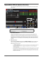
1
MC1-MK
Master Control Switcher
Operation Manual
Thank you for choosing Ross
You've made a great choice. We expect you will be very happy with your purchase of Ross Technology.
Our mission is to:
1. Provide a Superior Customer Experience
• offer the best product quality and support
2. Make Cool Practical Technology
• develop great products that customers love
Ross has become well known for the Ross Video Code of Ethics. It guides our interactions and
empowers our employees. I hope you enjoy reading it below.
If anything at all with your Ross experience does not live up to your expectations be sure to reach out to
us at [email protected].
David Ross
CEO, Ross Video
[email protected]
Ross Video Code of Ethics
Any company is the sum total of the people that make things happen. At Ross, our employees are a
special group. Our employees truly care about doing a great job and delivering a high quality customer
experience every day. This code of ethics hangs on the wall of all Ross Video locations to guide our
behavior:
1. We will always act in our customers’ best interest.
2. We will do our best to understand our customers’ requirements.
3. We will not ship crap.
4. We will be great to work with.
5. We will do something extra for our customers, as an apology, when something big goes wrong and
it's our fault.
6. We will keep our promises.
7. We will treat the competition with respect.
8. We will cooperate with and help other friendly companies.
9. We will go above and beyond in times of crisis. If there's no one to authorize the required action in
times of company or customer crisis - do what you know in your heart is right. (You may rent
helicopters if necessary.)
MC1-MK Operation Manual
•
Ross Part Number: MC1MKDR-004B-08
•
Release Date: March 23, 2015.
Copyright
© 2015 Ross Video Limited. Ross®, openGear®, and any related marks are trademarks or
registered trademarks of Ross Video Ltd. All other trademarks are the property of their respective
companies. PATENTS ISSUED and PENDING. All rights reserved. No part of this publication
may be reproduced, stored in a retrieval system, or transmitted in any form or by any means,
mechanical, photocopying, recording or otherwise, without the prior written permission of Ross
Video. While every precaution has been taken in the preparation of this document, Ross Video
assumes no responsibility for errors or omissions. Neither is any liability assumed for damages
resulting from the use of the information contained herein.
Patents
Patent numbers US 7,034,886; US 7,508,455; US 7,602,446; US 7,802,802 B2; US 7,834,886;
US 7,914,332; US 8,307,284; US 8,407,374 B2; US 8,499,019 B2; US 8,519,949 B2; US
8,743,292 B2; GB 2,419,119 B; GB 2,447,380 B; and other patents pending.
Important Regulatory and Safety Notices to Service Personnel
Before using this product and nay associated equipment, refer to the “Important Safety
Instructions” listed below to avoid personnel injury and to prevent product damage.
Product may require specific equipment, and/or installation procedures to be carried out to satisfy
certain regulatory compliance requirements. Notices have been included in this publication to call
attention to these specific requirements.
Symbol Meanings
This symbol on the equipment refers you to important operating and maintenance (servicing)
instructions within the Product Manual Documentation. Failure to heed this information may
present a major risk of damage to persons or equipment.
Warning — The symbol with the word “Warning” within the equipment manual indicates a
potentially hazardous situation, which, if not avoided, could result in death or serious injury.
Caution — The symbol with the word “Caution” within the equipment manual indicates a
potentially hazardous situation, which, if not avoided, may result in minor or moderate injury. It
may also be used to alert against unsafe practices.
Notice — The symbol with the word “Notice” within the equipment manual indicates a
potentially hazardous situation, which, if not avoided, may result in major or minor equipment
damage or a situation which could place the equipment in a non-compliant operating state.
ESD Susceptibility — This symbol is used to alert the user that an electrical or electronic
device or assembly is susceptible to damage from an ESD event.
Important Safety Instructions
Caution — This product is intended to be a component product of the DFR-8300 and
OG3-FR series frame. Refer to the DFR-8300 and OG3-FR Series Frame User Manual for
important safety instructions regarding the proper installation and safe operation of the frame
as well as its component products.
Warning — Certain parts of this equipment namely the power supply area still present a
safety hazard, with the power switch in the OFF position. To avoid electrical shock, disconnect
all A/C power cords from the chassis’ rear appliance connectors before servicing this area.
Warning — Service barriers within this product are intended to protect the operator and
service personnel from hazardous voltages. For continued safety, replace all barriers after any
servicing.
This product contains safety critical parts, which if incorrectly replaced may present a risk of
fire or electrical shock. Components contained with the product’s power supplies and power
supply area, are not intended to be customer serviced and should be returned to the factory for
repair. To reduce the risk of fire, replacement fuses must be the same time and rating. Only use
attachments/accessories specified by the manufacturer.
Warning — This product includes an “Ethernet Port” which allows this product to be
connected to a local area network (LAN). Only connect to networks that remain inside the
building. Do not connect to networks that go outside the building.
EMC Notices
United States of America
FCC Part 15
This equipment has been tested and found to comply with the limits for a class A Digital device,
pursuant to part 15 of the FCC Rules. These limits are designed to provide reasonable protection
against harmful interference when the equipment is operated in a commercial environment. This
equipment generates, uses, and can radiate radio frequency energy and, if not installed and used
in accordance with the instruction manual, may cause harmful interference to radio
communications. Operation of this equipment in a residential area is likely to cause harmful
interference in which case the user will be required to correct the interference at their own
expense.
Notice — Changes or modifications to this equipment not expressly approved by Ross Video
Limited could void the user’s authority to operate this equipment.
CANADA
This Class “A” digital apparatus complies with Canadian ICES-003.
Cet appareil numérique de la classe “A” est conforme a la norme NMB-003 du Canada.
EUROPE
This equipment is in compliance with the essential requirements and other relevant provisions of
CE Directive 93/68/EEC.
INTERNATIONAL
This equipment has been tested to CISPR 22:1997 along with amendments A1:2000 and
A2:2002, and found to comply with the limits for a Class A Digital device.
Notice — This is a Class A product. In domestic environments, this product may cause radio
interference, in which case the user may have to take adequate measures.
Maintenance/User Serviceable Parts
Routine maintenance to this openGear product is not required. This product contains no user
serviceable parts. If the module does not appear to be working properly, please contact Technical
Support using the numbers listed under the “Contact Us” section on the last page of this manual.
All openGear products are covered by a generous 5-year warranty and will be repaired without
charge for materials or labor within this period. See the “Warranty and Repair Policy” section in
this manual for details.
Environmental Information
The equipment that you purchased required the extraction and use of natural
resources for its production. It may contain hazardous substances that could
impact health and the environment.
To avoid the potential release of those substances into the environment and to diminish the need
for the extraction of natural resources, Ross Video encourages you to use the appropriate
take-back systems. These systems will reuse or recycle most of the materials from your
end-of-life equipment in an environmentally friendly and health conscious manner.
The crossed out wheelie bin symbol invites you to use these systems.
If you need more information on the collection, reuse, and recycling systems, please contact your
local or regional waste administration.
You can also contact Ross Video for more information on the environmental performance of our
products.
Company Address
Ross Video Limited
Ross Video Incorporated
8 John Street
P.O. Box 880
Iroquois, Ontario, K0E 1K0
Ogdensburg, New York
Canada
USA 13669-0880
General Business Office: (+1) 613 • 652 • 4886
Fax: (+1) 613 • 652 • 4425
Technical Support: (+1) 613 • 652 • 4886
After Hours Emergency: (+1) 613 • 349 • 0006
E-mail (Technical Support): [email protected]
E-mail (General Information): [email protected]
Website: http://www.rossvideo.com
Contents
On Air Control Overview
1
In This Chapter .................................................................................................................... 1-1
Navigating to the On Air Control Interface ......................................................................... 1-2
Menu System Basics............................................................................................................ 1-3
Switcher Basics.................................................................................................................... 1-5
Video Sources........................................................................................................ 1-5
Video Layering...................................................................................................... 1-5
Video Preview ....................................................................................................... 1-5
Overlay .................................................................................................................. 1-5
Multiple MC1-MK Operation ............................................................................... 1-5
Keying
2
In This Chapter .................................................................................................................... 2-1
Keyers Overview ................................................................................................................. 2-2
Configuring a Key ............................................................................................................... 2-3
Overview ............................................................................................................... 2-3
Transitions
3
In This Chapter .................................................................................................................... 3-1
Transition Area .................................................................................................................... 3-2
Performing Transitions ........................................................................................................ 3-4
SqueezeBack Effects
4
In This Chapter .................................................................................................................... 4-1
SqueezeBack Effects Options Overview ............................................................................. 4-2
Working in 2D Space........................................................................................................... 4-4
Configuring a SqueezeBack Preset...................................................................................... 4-5
Performing Transitions with SqueezeBack Presets ............................................................. 4-6
Notes on Performing Transitions with SqueezeBack Presets................................ 4-6
Previewing a Squeeze Effect ................................................................................. 4-6
Transitions with SqueezeBack .............................................................................. 4-6
Audio
5
In This Chapter .................................................................................................................... 5-1
Audio Interfaces................................................................................................................... 5-2
Audio Overview................................................................................................................... 5-4
Audio Modes ......................................................................................................... 5-4
Gain and Duck Levels ........................................................................................... 5-4
Audio Shuffling ..................................................................................................... 5-4
Audio Processing................................................................................................... 5-5
Audio Profiles........................................................................................................ 5-5
Transitions ............................................................................................................. 5-5
Setting the Master Audio Level ........................................................................................... 5-6
Audio Processing ................................................................................................................. 5-7
MC1-MK Operation Manual (Iss. 08)
Contents • i
Audio Shuffling.................................................................................................................... 5-8
Performing Transitions......................................................................................................... 5-9
Using Audio Profiles.......................................................................................................... 5-10
Recalling an Audio Profile .................................................................................. 5-10
EAS Audio ......................................................................................................................... 5-11
Voice Overs........................................................................................................................ 5-12
Setting the Voice Over Duck/Gain Level ............................................................ 5-12
Including a Voice Over........................................................................................ 5-13
Media File Management
6
In This Chapter..................................................................................................................... 6-1
Loading Media Files ............................................................................................................ 6-2
Loading a Media File............................................................................................. 6-2
Managing Media Files.......................................................................................................... 6-4
Media File Notes.................................................................................................... 6-4
Image Specifications.............................................................................................. 6-4
File Naming Specifications.................................................................................... 6-5
Connection using FTP ........................................................................................... 6-5
Connection using RossLinq ................................................................................... 6-5
CompactFlash® Card ............................................................................................ 6-6
Adjusting On-Air Properties ................................................................................................ 6-7
Displaying Timecode in a Logo Channel............................................................................. 6-8
Overview................................................................................................................ 6-8
To display timecode in a logo channel .................................................................. 6-8
Configuration Notes............................................................................................... 6-9
Appendix A. DashBoard Menus
7
In This Appendix.................................................................................................................. 7-1
Home Tab............................................................................................................................. 7-2
Keyers Tabs.......................................................................................................................... 7-3
Logos Tabs ........................................................................................................................... 7-4
SqueezeBack Effects Tabs ................................................................................................... 7-6
External Sources Tab ........................................................................................................... 7-7
Voice Over Tab .................................................................................................................... 7-8
Audio Processing Tab .......................................................................................................... 7-9
Audio Shuffle Tab.............................................................................................................. 7-10
Index
ii • Contents
IX
MC1-MK Operation Manual (Iss. 08)
On Air Control Overview
In This Chapter
This chapter provides a basic introduction to the MC1-MK, including an overview of the different
areas of the On Air Control interface, using the menu system, as well as a brief summary of how
video is controlled by the MC1-MK.
The following topics are discussed:
•
Navigating to the On Air Control Interface
•
Menu System Basics
•
Switcher Basics
MC1-MK Operation Manual (Iss. 08)
On Air Control Overview • 1–1
Navigating to the On Air Control Interface
This section provides a brief overview of navigating the MC1-MK interface in DashBoard.
To launch DashBoard
1. Ensure that you are running DashBoard software version 6.2.0 or higher. The software
and DashBoard User Manual are available from the Ross Video website.
2. Launch DashBoard by double-clicking its icon on your desktop.
3. Locate the MC1-MK in the Basic Tree View of DashBoard. If the card does not appear,
consult the MFC-8300 Series or MFC-OG3 Series User Manual and DashBoard User
Manual.
To access the MC1-MK On Air Control interface
1. From the Tree View, expand the node for the MC1-MK you wish to access.
2. Select the On Air Control node to display the interface in the right-half of DashBoard.
To set the MC1-MK On Air Control interface to full-screen
1. Press Shift+F11 to display the interface in full-screen mode. You can also select
Window > Full Screen from the DashBoard toolbar.
2. To exit out of full-screen mode, press Shift+F11 again.
To lock the MC1-MK interface
1. To lock the interface, select the Lock button located in the upper right corner of the On
Air Control interface.
2. To unlock the interface, use the provided Unlock spinner.
1–2 • On Air Control Overview
MC1-MK Operation Manual (Iss. 08)
Menu System Basics
The On Air Control interface enables you to set up and perform transitions, configure keyers,
monitor and control audio levels. This section provides a brief overview of the controls available
in this interface.
Figure 1.1 MC1-MK — On Air Control Interface
1) Channel Select Buttons
5) Crosspoint Buses
9) Automation Button
2) Setup Tabs
6) Transition Area
10) Program Audio Area
3) Audio Meters
7) Keyer Area
11) Lock Button
4) Timer Display
8) Fade to Black Button
1. Channel Select Buttons
This area includes buttons that allow you to toggle between multiple MC1-MK interfaces.
Selecting a button displays the corresponding MC1-MK On Air Control interface in DashBoard.
A lit button indicates that the corresponding On Air Control interface is the currently active one
in DashBoard. The icons on these buttons can be changed as described in the MC1-MK
Installation Manual.
By default, and after a factory default reset is performed, these buttons do not display an icon (the
button faces are blank).
2. Setup Tabs
The tabs located near the top left of the interface provide options for configuring the keyers,
on-air controls, and selecting logo channel sources. Refer to the chapter “Appendix A.
DashBoard Menus” on page 7-1 for a list of the tabs and parameters available.
MC1-MK Operation Manual (Iss. 08)
On Air Control Overview • 1–3
3. Audio Meters
The On Air Control interface displays an audio meter for the first eight audio channels of
Program and Preset (note that display will not be real-time). The meter scale ranges from 0 to
-120dBFS. Refer to the section “Audio Interfaces” on page 5-2 for details.
4. Timer Display
This display is a free running timer that counts to a maximum of 23:59:59 (hh:mm:ss) and can be
reset to 00:00:00 using the Reset button.
5. Crosspoint Buses
This area is used to select the video sources for each bus. Each crosspoint button will display the
name of its source on the button face. The last button of the row is a Shift button, which provides
access to 10 additional selectable crosspoints. The default bus mapping is outlined in the
MC1-MK Installation Manual. The following buses are available:
•
Program Bus — The Program Bus is used to select the video source that will show as the
Background on the Program output. After performing a factory default reset, the first
unshifted router source (Router 1) is selected on this bus.
•
Preset Bus — The Preset Bus is used to select the video source that is visible on the
Preview output. After performing a factory default reset, the second unshifted router
source (Router 2) is selected on this bus.
6. Transition Area
This area provides the options for selecting transition rates (slow, medium, fast), and type (take,
fade-fade, take-fade, mix, fade-take, and SqueezeBack). Refer to the chapter “Transitions” on
page 3-1 for details.
7. Keyer Area
This area includes the four keyers of the MC1-MK and allows you to perform the key transitions.
Refer to the chapter “Keying” on page 2-1 for details.
8. Fade to Black Button
Use this button to fade the Program bus to black. The Fade to Black (FTB) rate is specified in the
Home tab. After performing a factory default reset, this button is toggled off (unlit).
You can also disable this button using the option available in the Personality tab. Refer to the
MC1-MK Installation Manual for details on configuring the option.
9. Automation Button
Toggling this button on (button will be lit) allows an Automation System to control the MC1-MK.
After performing a factory default reset, this button is toggled off (unlit).
10. Program Audio Area
This area includes an audio fader that enables you to control the Program audio gain. The slider is
set by default to 0 and has a range of -72 to +12dB. Use the Default button to reset the audio
gain. You can also configure an option in the Personality tab to automatically reset the audio gain
to 0dB after any Background transition. Refer to the MC1-MK Installation Manual for details on
configuring the option.
11. Lock Button
Use this button to lock the interface so that users are locked-out of the interface. This prevents
anyone from changing settings on this MC1-MK interface. To lock the interface, select the
button. To unlock, use the provided Unlock rotary spinner.
1–4 • On Air Control Overview
MC1-MK Operation Manual (Iss. 08)
Switcher Basics
This section gives an overview of how video is controlled by the MC1-MK. This includes video
sources, video layering, and preview. For information on setting up crosspoints and video inputs,
refer to the MC1-MK Installation Manual.
Video Sources
The MC1-MK has access to two basic types of video sources: external and internal. All video
sources can be assigned to video source (crosspoint) buttons. By pressing a crosspoint button on a
bus, the video source assigned to that button is selected.
•
External — External video sources come from SDI inputs on the rear module.
•
Internal — Internal video sources come from internally generated video, such as any of
the four internally generated Logo channels, or an internally generated black.
To select a video source on a bus, you must identify the bus you want to assign a video source to
and then press the crosspoint button you want to select on that bus.
Video Layering
Key layering is fixed for the MC1-MK and starts with Background and proceeds to Keyer 4.
Figure 1.2 Video Layering
Video Preview
Video preview allows you to use an additional monitor to preview what the next shot is going to
be. The Preset bus of MC1-MK shows what is selected for the next transition. This includes the
keys and background video sources that will be on-air after the next transition.
Overlay
The overlay feature provides one layer of text, in real time, as a source for any Keyer. The text
can be from an EAS or LTC source.
Multiple MC1-MK Operation
DashBoard enables you to have multiple On Air Control interfaces open with each interface for a
specific MC1-MK Master Control Switcher. Refer to the MC1-MK Installation Manual for
details on setting up multiple cards.
MC1-MK Operation Manual (Iss. 08)
On Air Control Overview • 1–5
1–6 • On Air Control Overview
MC1-MK Operation Manual (Iss. 08)
Keying
In This Chapter
Keying is the term used to describe when you insert (or electronically cut) portions of one screen
into another, or place titles over background images. Keys are made up of two basic components:
an alpha (that cuts the hole in the background video), and a fill (that fills the hole with different
video). This chapter provides a summary of the MC1-MK keying features.
The following topics are discussed:
•
Keyers Overview
•
Configuring a Key
MC1-MK Operation Manual (Iss. 08)
Keying • 2–1
Keyers Overview
MC1-MK includes four high quality HD/SD-SDI video keyers. In addition to the external Key
Video and Key Alpha source, there are also four internal static/animation playout channels. An
excellent device for keying external devices such as character generators, graphic systems and
EAS devices into a program feed and/or keying with four internal logo channels.
The card offers full key control with shaped and unshaped keying, self key or auto key, with clip
and gain control.
Figure 2.1 Keyer Controls
1) Keyers Tab
3) Program Keyer Select Buttons
2) Logos Tab
4) Preset Keyer Select Buttons
1. Keyers Tab
Each keyer has a sub-tab that enables you to select video sources, key types, and adjust
transparency, clip, and gain. The MC1-MK supports Auto Select and Self keys. The External
sub-tab enables you to specify the router source that feeds input on the KEY VIDEO Input or
KEY ALPHA Input used as the External source when configuring keyers.
2. Logos Tab
Each logo channel has a sub-tab in the Logos tab that enables you to specify the media files the
channel uses. Refer to the section “Loading Media Files” on page 6-2 for details.
3. Program Keyer Select Buttons
When lit red, a button indicates that specific keyer is currently on-air on the Program bus.
Selecting a button will immediately perform cuts on that keyer.
4. Preset Keyer Select Buttons
These buttons are used to choose which keyer is included in the next transition. Note that
depending on a Personality tab setting, once a transition is performed, the buttons are no longer
lit.
2–2 • Keying
MC1-MK Operation Manual (Iss. 08)
Configuring a Key
The MC1-MK provides the ability to associate each keyer (1-4) with the following sources:
external key video/fill, or a logo channel. This section briefly describes how to set up Key
Alphas, Auto Keys, adjust the clip and gain values.
For More Information on...
•
specifying the Preset Keyers behavior, refer to the MC1-MK Installation Manual.
•
the Keyers menu items, refer to Table 7.2 on page 7-3.
•
loading media files to logo channels, refer to the section “Loading Media Files” on
page 6-2.
•
performing transitions, refer to the section “Performing Transitions” on page 3-4.
Overview
This section outlines the key types and key alpha types supported by the MC1-MK.
Key Types
The MC1-MK supports the following key types:
•
Auto Select — An Auto Select Key uses two video signals: the Key Alpha is used to cut
the hole in the video, and the Key Video is used to fill the hole. For external keying, the
source on BNC 2 is the Key Video and the source on BNC 4 is the Key Alpha. For
internal sources, the Key Video and Alpha are generated internally (BNC 2 and BNC 4
are not used). Note that the Key Alpha Type is automatically set to Shaped.
•
Self — A Self Key uses only one video signal: the luminance (or brightness) of the Key
Video is used as the Key Alpha. For external keying, the source on BNC 2 is used as the
Key Video and the Key Alpha (BNC 4) is not used. For internal sources, the Key Video is
internally supplied (BNC 2 nor BNC 4 are used). Note that the Key Alpha Type is
automatically set to Unshaped.
Key Alpha Types
You can specify a key alpha as one of the following:
•
Unshaped (multiplicative keying) — With an Unshaped Key, the Key Alpha luminance
value mixes linearly the Key Video with the Background. Shades of gray, in the Key
Alpha, are translated into transparency levels, giving the key a soft edge. Self Keys are
set to Unshaped by default.
•
Shaped (additive keying) — With a Shaped Key, the Key Alpha cuts a hole in the
Background based on the luminance value of the Key Alpha and adds the Key Video to
the Background hole. Shaped Key alphas are sometimes used with Character Generators
to cut very precise holes for the Key Video fill. Auto Select keys are set to Shaped by
default.
MC1-MK Operation Manual (Iss. 08)
Keying • 2–3
Configuring Key Sources
You can assign any of the four logo channels or a router crosspoint as the source for a keyer. The
specific router crosspoint assigned to the Key Video source can be selected using the options in
the External tab.
Note — Leave Logo 4 assigned to Key 4 to ensure that EAS text crawls output
properly.
To configure a key
1. From the Tree View, expand the node for the MC1-MK you wish to access.
2. Select the On Air Control node to display the interface in the right-half of DashBoard.
3. Select the Keyers tab.
4. From the Keyers tab, select the tab for the key you wish to configure.
5. From the Keyer Source area, select the button for the video source you want to assign to
the Keyer. The button for the selected source is now lit. If you selected External, you
may also need to specify the router crosspoint as outlined in the section “To specify a
router crosspoint as the External Keyer source” below.
6. Toggle the Key Type button to set the Key Type to Auto Select or Self.
7. If required, toggle the Key Alpha Type button to set the Key Alpha Type to Unshaped
or Shaped.
8. Adjust the Clip and Gain values of the key using the corresponding sliders.
Note — Ross Video strongly recommends leaving the Clip and Gain values at the
default settings to avoid undesirable effects.
9. Use the Transparency slider to adjust the transparency level of the key.
10. Toggle the Key Invert button to specify whether the key is inverted.
To specify a router crosspoint as the External Keyer source
1. From the Tree View, expand the node for the MC1-MK you wish to access.
2. Select the On Air Control node to display the interface in the right-half of DashBoard.
3. Select the External Sources tab.
4. From the External Sources row, select the button for the router crosspoint you want to
assign as the External source. The button is now lit and this crosspoint will be used
whenever External is selected as the source for any Keyer. The crosspoint is identified
by the default name displayed on the button in the External sub-tab.
For More Information on...
•
2–4 • Keying
changing the crosspoint naming and/or mapping, refer to the MC1-MK Installation
Manual.
MC1-MK Operation Manual (Iss. 08)
Transitions
In This Chapter
This chapter provides a summary of performing transitions in DashBoard. For information on
performing SqueezeBack transitions, refer to the chapter “SqueezeBack Effects” on page 4-1.
The following topics are discussed:
•
Transition Area
•
Performing Transitions
MC1-MK Operation Manual (Iss. 08)
Transitions • 3–1
Transition Area
Transitions are used to change the background video and take keys on and off-air. A transition can
include any combination of Background video, and keys. The BKGD A (Program) and BKGD B
(Preset) inputs allows for background dissolves and V-Fades behind the external key source.
Figure 3.1 Transition Area
1) Keyer Area
3) Transition Speed Buttons
5) SQUEEZE Button
2) Transition Type Buttons
4) BKGD Button
6) TAKE Button
1. Keyer Area
The Keyer Area enables you to add, or remove, keyers in transitions. This area includes the
following controls:
•
The top row of buttons, labeled Key 1-4, are used to perform cuts on the specified keyer
directly on the Program Bus, without affecting their inclusion in the next transition. A lit
button indicates that the specified keyer is currently on-air.
•
The middle row displays thumbnails of the video source selected for that keyer when
possible. Note that images are only provided for the internal logo sources and not for
external router sources.
•
The bottom row of buttons, labeled Key 1-4, are used to add, or remove, the specified
keyer to the next transition. Selecting the button toggles the keyer on/off and
selects/removes the keyer to the Preset Bus respectively. Once the transition is executed,
and depending on a Personality tab setting, the button(s) are no longer lit in this row but
are lit red in the top row.
•
Refer to the section “Audio Interfaces” on page 5-2 for information on the AUDIO
OVER buttons.
2. Transition Type Buttons
The following Transition Type buttons are available (from left to right):
3–2 • Transitions
MC1-MK Operation Manual (Iss. 08)
•
— Select this button to perform a cut transition from one source to the next or to cut
to a squeeze effect. This type can be combined with a squeeze effect.
•
— Select this button to perform a V-Fade transition from the Program source to Black
to the Preset source. The MC1-MK fades down from one source to black and then
transitions to the next source. During a hot-punch transition, the video performs a CUT
while the audio performs a V-Fade. This type can be combined with a squeeze effect.
•
— Select this button to perform a cut to black, then fade up to the next source. This
type can be combined with a squeeze effect.
•
— Select this button to perform a gradual fade from one source to the next. The
MC1-MK performs a cross fade between sources. Note that this button is selected after
performing a factory default reset. This type can be combined with a squeeze effect.
•
— Select this button to fade from one source to black and then cut to the next source.
This type can be combined with a squeeze effect.
•
— Select this button to perform a SqueezeBack effect by reducing the size of the
video over time to the dimensions set in the Squeeze Effects tab. Unlike the above types,
you may not change your background or keys on-air with this transition type. The
corresponding buttons are grayed out.
3. Transition Speed Buttons
These buttons apply the rate (slow, medium, fast) to the next transition. The transition rates are
specified in the Home tab. Note that the Slow button is selected after performing a factory
default reset.
Note that if you are controlling the MC1-MK via Automation, and these buttons are not lit, the
transition rate applied is set by the Automation command. If you wish to apply one of these rates,
remember to select the required transition speed button before performing a transition (e.g.
selecting TAKE).
4. BKGD Button
The BKGD button is used to add, or remove, the BKGD from the next transition. Toggling this
button will immediately affect the Background video that is visible on the Preset output.
5. SQUEEZE Button
The SQUEEZE button is used to add or remove, the selected squeeze effect preset from the next
transition. Toggling this button will immediately affect the video that is visible on the Preset
output. You may not de-select this button if a squeeze effect is on-air. This can be done with a
Squeeze transition to perform a SqueezeBack, or as part of another transition (Take, Mix,
Fade-Fade).
6. TAKE Button
Selecting the TAKE button performs the transition between the sources and effects selected in the
Program and Preset buses, using the specified Transition Type and Transition Speed. The
button is labeled TAKE NEXT when Automation is configured and enabled (the ATMN button is
toggled ON), and the Take Button on Panel setting is set to Take Next in the Personality tab.
For More Information on...
•
the corresponding buttons in the Keyers Area, refer to the chapter “Keyers Overview”
on page 2-2.
•
the Take Button on Panel setting, refer to the MC1-MK Installation Manual.
•
configuring remote control via an automation protocol, refer to the MC1-MK Installation
Manual.
MC1-MK Operation Manual (Iss. 08)
Transitions • 3–3
Performing Transitions
You can perform transitions in one of the following manners: hot-punching a crosspoint on the
Program bus, selecting a Keyer (1-4) button from the Keyer Area to transition a keyer on or off
air, and using the options in the Transition Area to add elements to the transition.
To set the transition rate
1. From the Tree View, expand the node for the MC1-MK you wish to access.
2. Select the On Air Control node to display the interface in the right-half of DashBoard.
3. Select the Home tab.
4. Specify the rate, in number of frames, as required, in the Slow Rate, Medium Rate and
Fast Rate fields.
5. Set the Fade to Black transition rate using the FTB Rate field.
To perform a transition
1. From the Tree View, expand the node for the MC1-MK you wish to access.
2. Select the On Air Control node to display the interface in the right-half of DashBoard.
3. In the Transition Area, select the elements you want to add to the next transition by
selecting the BKGD button to add the Background video source, and the Key 1-4
buttons to add the required keyer(s).
4. On the Preset bus, select the video source you want to take on-air.
5. Select a Transition Speed button (Slow, Medium, or Fast).
6. Select a Transition Type button.
7. Select Take.
To perform a Fade to Black
The FTB button allows you to fade to black, where the Program bus is faded to black at the FTB
rate, the audio goes to silence, and closed captioning information is not passed. The Fade to Black
rate is set in the Home tab as outlined above. When the FTB button is selected, or lit, the
MC1-MK performs an Auto transition to black.
Selecting the FTB button does not affect EAS audio, however any EAS text will be removed
from the output.
Transition Notes
Keep the following in mind when performing transitions:
3–4 • Transitions
•
To allow for audio cross fading, a cut takes two frames. One frame is used for the audio
fade down, the video is then cut, followed by the one frame audio fade up.
•
The speed at which the Auto transition is performed, in number of frames, is determined
by the setting (Slow, Medium, or Fast) in the Transition Rate area. Before proceeding,
ensure the Transition Type is set to the desired type.
•
When switching between router sources, there is an additional time after the (visible)
transition, while the router sources are switched. If you see a glitch at the end of the
transition, this indicates that the Delay setting in the Router setup tab is set too low.
•
If a crosspoint or transition button is selected while a transition is in progress, the original
transition continues as subsequent button presses are ignored (except the FTB button).
MC1-MK Operation Manual (Iss. 08)
•
Verify how the Toggle Program/Preset Bus and Disarm Preset Keyers options are
configured in the Personality tab. Refer to the MC1-MK Installation Manual for details
on configuring these options.
MC1-MK Operation Manual (Iss. 08)
Transitions • 3–5
3–6 • Transitions
MC1-MK Operation Manual (Iss. 08)
SqueezeBack Effects
In This Chapter
The MC1-MK can be used to perform on-air SqueezeBack transitions to reveal another video
source or graphic. You can also transition to pre-squeezed effects with standard transitions,
squeeze in any direction on either X or Y axis, or both. Four SqueezeBack presets are provided
for quick effect recalls on the fly. This chapter outlines the SqueezeBack feature of the MC1-MK.
The following topics are discussed:
•
SqueezeBack Effects Options Overview
•
Working in 2D Space
•
Configuring a SqueezeBack Preset
•
Performing Transitions with SqueezeBack Presets
MC1-MK Operation Manual (Iss. 08)
SqueezeBack Effects • 4–1
SqueezeBack Effects Options Overview
This section briefly outlines the elements of the On Air Control interface for the SqueezeBack
Effects feature.
4
Figure 4.1 SqueezeBack Effects Controls
1) SqueezeBack Effects Tab
3) SqueezeBack Effect Transition Type Button
2) Effect Select Area
4) SQUEEZE Button
1. SqueezeBack Effects Tab
The SqueezeBack Effects tab provides a sub-tab for each of the four SqueezeBack presets,
enabling you to customize each effect separately. From these sub-tabs you can specify the
horizontal and vertical positions of the image on the screen, and the reveal source from the four
logo channels or an external video source. Because the reveal source shares the same sources
available to the keyers, we encourage users to avoid sharing a source between keyer and reveal
operation.
2. Effect Select Area
This area includes the Effect # status field and an EFFECT SELECT button. The status field
reports the last applied effect and whether it is on or off air, or currently on the Preset Bus.
While the squeeze effect is on air:
•
the EFFECT SELECT button is locked. Even though you can still adjust the options in
the SqueezeBack Effects tabs, we suggest not doing so since all effect changes are
immediately applied.
•
you are unable to change the background or keys with a transition. However, you can still
hot-punch a source or key on the Program bus. However, hot-punching a source on the
Program bus will take the squeeze effect off air. Hot-punching keys on/off will not take
the squeeze effect off air.
4–2 • SqueezeBack Effects
MC1-MK Operation Manual (Iss. 08)
3. SqueezeBack Effect Transition Type Button
Selecting this button performs a SqueezeBack effect with the transition. You must pre-configure
your SqueezeBack presets, then select the preset you want to apply to the transition before
executing your transition.
4. SQUEEZE Button
Selecting this button applies the squeeze effect (as specified using the EFFECT SELECT
button) to the next transition. Note that the SQUEEZE button will be selected (lit) yet locked out
when the transition type is Squeeze, or when a squeeze effect is on air.
MC1-MK Operation Manual (Iss. 08)
SqueezeBack Effects • 4–3
Working in 2D Space
In order to maximize the features of the SqueezeBack feature, it helps to have a basic
understanding of two-dimensional (2D) space. Two axes (X and Y) are used to define 2D space.
The position of an image on each of the two axes determines its location in 2D space.
•
X — Refers to the horizontal (left-right) position of the image on the screen.
•
Y — Refers to the vertical (up-down) position of the image on the screen.
-Y
Y Axis
+X
is
-X
X Ax
Center Point or Zero Point
+Y
Figure 4.2 Basics of 2D Space
Image Position in 2D Space
The center point of the screen is the center (zero) point. Each axis has a positive and negative
region.
•
Moving an image to the left of the center (or zero) point locates it in -X space.
•
Moving an image to the right of the center locates it in +X space.
•
Moving an image below the center point locates it in +Y space.
•
Moving an image above the center point locates it in -Y space.
When working with images, keep in mind that the 2D space extends beyond the visible area of
the screen. Images can be positioned and manipulated outside of the viewable area to create some
interesting effects. For example, and image can be positioned in such a way that it appears to roll
into view from a point outside the screen and roll out of view on the other side.
4–4 • SqueezeBack Effects
MC1-MK Operation Manual (Iss. 08)
Configuring a SqueezeBack Preset
This section outlines how to configure Preset Effect 1 in preparation of including it in a transition.
The same procedure can be used to configure any of the effect presets for your MC1-MK.
Note — You cannot change the size of the image. You can only change the distance
of the image from the center point.
For More Information on...
•
the menu options when configuring your SqueezeBack presets, refer to Table 7.4 on
page 7-6.
To configure an effect
1. From the Tree View, expand the node for the MC1-MK you wish to access.
2. Select the On Air Control node to display the interface in the right-half of DashBoard.
3. Select the SqueezeBack Effects tab.
4. Select the Effect 1 tab to configure the first effect.
5. To specify the position of the image in the viewing area of the screen:
•
Use the X Position slider to adjust the horizontal position of the image on the
screen.
•
Use the Y Position slider to adjust the vertical position of the image on the screen.
6. To squeeze the image appearance:
•
Use the X Size slider to squeeze horizontally.
•
Use the Y Size slider to squeeze vertically.
•
Select the Lock Aspect Ratio check box to squeeze in both directions at the same
time.
Note — You can reset the image to the default image settings by pressing Reset to
Defaults.
7. In the Reveal Source area, select the video source the squeeze effect will reveal.
MC1-MK Operation Manual (Iss. 08)
SqueezeBack Effects • 4–5
Performing Transitions with SqueezeBack Presets
This section provides examples of performing transitions with SqueezeBack Presets. Your
requirements may differ from what is presented here.
Notes on Performing Transitions with SqueezeBack Presets
Keep the following in mind when performing transitions with SqueezeBack presets:
•
You can pre-define up to four different SqueezeBack Presets (Effects 1-4)
•
A squeeze effect does not consume any existing keyers and you can specify any of the
logo channels to use as a reveal source for that effect.
•
When the video format is 480i 59.94, the Line 21 closed captioning is re-inserted from
the video source into the output of the MC1-MK when the NTSC Pass Line 21 setting is
enabled. Refer to the MC1-MK Installation Manual for details.
•
If a squeeze effect is on air and you press a crosspoint on the Program bus, the squeeze
effect will be cleared from Program and the new crosspoint will be put on air.
•
Squeeze effect transitions are also supported under the Presmaster automation protocol.
Refer to the MC1-MK Installation Manual for details on this protocol.
•
You can also trigger a squeeze effect using a GPI trigger. Refer to the MC1-MK
Installation Manual for setup details.
•
You can configure a tally to raise when the reveal source is visible. This tally will be
raised regardless of the configured source. This can be used in cases when a graphics
station is providing the video and needs to know when to trigger the playing of an
animation. Refer to the MC1-MK Installation Manual for setup details.
Previewing a Squeeze Effect
You can preview your Effect preset on the Preview monitor without affecting the Program bus.
However, during a SqueezeBack transition the preview output is not accurate.
To preview a squeeze effect
1. Set up your effect as outlined in the procedure “To configure an effect” on page 4-5.
2. From the Tree View, expand the node for the MC1-MK you wish to access.
3. Select the On Air Control node to display the interface in the right-half of DashBoard.
4. Use the EFFECT SELECT button to specify the desired squeeze effect for the
transition.
5. Select the SQUEEZE button.
Transitions with SqueezeBack
This section provides examples of executing transitions that include SqueezeBack Preset.
Basic Transition with a Squeeze Effect
Operation: This is a SqueezeBack transition.
4–6 • SqueezeBack Effects
MC1-MK Operation Manual (Iss. 08)
1. Set up your effect using the tabs in the SqueezeBack Effects tab as outlined in the
section “Configuring a SqueezeBack Preset” on page 4-5.
2. Use the EFFECT SELECT button to specify the desired squeeze effect for the
transition. This is the effect that you configured in step 1.
3. Select
in the Transition Type area. The Effect # status field now indicates ON PST.
You can preview the squeeze dimensions on your Preview monitor.
4. Select the SQUEEZE button.
5. Select TAKE.
Dissolve to a Static Squeeze Effect
Prerequisite: You have a pre-squeezed effect ready on Preview.
Description: When you select TAKE, the Program dissolves to the pre-squeezed effect. After you
have set up the transition, and during the transition, the Preview monitor is accurate.
Operation:
1. Select the EFFECT SELECT button to specify the desired squeeze effect for the
transition.
2. Select a dissolve transition type (Fade-Fade, Take-Fade).
3. Ensure the SQUEEZE button is selected.
4. The Preview monitor shows the squeeze effect.
MC1-MK Operation Manual (Iss. 08)
SqueezeBack Effects • 4–7
4–8 • SqueezeBack Effects
MC1-MK Operation Manual (Iss. 08)
Audio
In This Chapter
This chapter outlines the audio features of the On Air Control interface, using audio proc amps,
mapping channels, applying audio profiles, and using voice overs.
The following topics are discussed:
•
Audio Interfaces
•
Audio Overview
•
Setting the Master Audio Level
•
Audio Processing
•
Audio Shuffling
•
Performing Transitions
•
Using Audio Profiles
•
EAS Audio
•
Voice Overs
MC1-MK Operation Manual (Iss. 08)
Audio • 5–1
Audio Interfaces
This section briefly summarizes the audio monitoring and controls available in the On Air
Control interface for the MC1-MK.
Figure 5.1 On Air Control Interface — Audio
1) Voice Over Tab
3) Audio Shuffle Tab
5) AUDIO OVER Buttons
2) Audio Processing Tab
4) Audio Meters
6) Audio Fader Controls
1. Voice Over Tab
This tab provides options for configuring the duck level and gain for the voice over output.
2. Audio Processing Tab
The MC1-MK provides the ability to adjust the gain, or mute, individually, each of the 16
embedded channels. You can sum every adjacent pair of audio groups with the first channel on
the Odd Channel numbers (e.g. Channels 1 and 2, 3 and 4, 5 and 6 etc.). You can also recall audio
profiles from this tab.
This tab also indicates the crosspoint button currently selected on the Preset bus. This information
is displayed in blue text at the top of the tab contents. This information is useful when selecting
audio profiles, allowing you to see which crosspoint the audio profile will apply to during the
next transition.
3. Audio Shuffle Tab
The MC1-MK provides the flexibility to modify the map of audio channels inside the SDI bit
stream. This is useful when the incoming feed has multiple languages, with each language
consisting of a channel pair. By mapping the channels, you ensure that the proper language makes
it onto the Program air path, and that the other languages can be muted or removed from the air
path. You can also recall audio profiles from this tab. Refer to the section “Audio Shuffling” on
page 5-8 for details on using the options in this tab.
This tab also indicates the crosspoint button currently selected on the Preset bus. This information
is displayed in blue text at the top of the tab contents. This information is useful when selecting
5–2 • Audio
MC1-MK Operation Manual (Iss. 08)
audio profiles, allowing you to see which crosspoint the audio profile will apply to during the
next transition.
4. Audio Meters
This area displays Preset and Program audio peak level measurements for your audio channels.
Measurement units are in dBFS (decibel full scale) where 0dBFS is the maximum digital value.
Each audio meter displays audio level information as illustrated in Figure 5.2.
0.00 dBFS
- 2.25
- 4.50
- 6.75
- 9.00
-11.75
-14.50
-17.25
-20.00
-24.00
-28.00
-32.00
-36.00
-40.00
-45.00
-50.00
-60.00
-70.00
Figure 5.2 Illustrative Example of Audio Level Information
5. AUDIO OVER Buttons
An AUDIO OVER button is included on each bus. Selecting the button in the PST bus includes
the voice over channel in the next transition. You can also hot-punch the AUDIO OVER button
in the Program bus.
6. Audio Fader Controls
Use the slider to apply an audio gain value on the Program and Preset bus. The gain range is
-72dB to +12dB. Use the Reset Audio Gain button to set the gain value to 0.
MC1-MK Operation Manual (Iss. 08)
Audio • 5–3
Audio Overview
This section outlines the audio features such as gain and duck levels, channel mapping, applying
audio proc amps, transitions, and audio profiles.
Audio Modes
The MC1-MK can be operated in one of two ways: normal Audio Follow Video (AFV) mode, or
Override mode.
Audio Follow Video
The Audio Follow Video (AFV) mode is where an audio channel is taken to air when the video it
is associated with is taken to air. The audio will follow the video on and off-air like this for
transitions.
For example, there may be a number of camera setups in the studio, each on focusing on a
different talent. When a particular camera is taken on-air, you also want the audio from the
talent’s microphone to be taken on-air. When the camera is taken off-air, you also want the
corresponding audio channel to be taken off-air. This is normal AFV mode operation.
Audio Overrides
The Override mode is when the normal AFV mode has been altered, either by changing the gain,
taking more or fewer channels to air, or altering the channels that will be taken to air on the next
transition. Overrides are also applied by selecting one of the audio profiles.
For example, if you have an over the shoulder shot, the audio channels for both the talent and the
key would be on-air as per normal AFV. If you transition to a shot with only a VTR clip, then the
audio from the talent would be taken off-air. If you wanted both audio channels to remain, you
would have to set up an audio profile by turning on the audio crosspoint for the talent on the
Preset bus. When you make the transition, the MC1-MK takes the video off-air, but keeps the
audio on.
Gain and Duck Levels
EAS
Audio Input
Voice Over
When setting up the gain and duck levels, note that audio sources are layered with the EAS
positioned downstream from the Voice Over channel. For example, applying a duck level when
EAS is active, also applies that value to the Voice Over channel (if active) and the other incoming
audio sources. That means when both Voice Over and EAS audio are in effect, it is possible to
duck the incoming audio twice.
Figure 5.3 Audio Layering
Audio Shuffling
You can shuffle the 16 audio channels within the embedded Channels with no de-embedding
required. This re-shuffle is invoked in real time except when that input is on-air (the setting will
5–4 • Audio
MC1-MK Operation Manual (Iss. 08)
not be editable in this case). For the case where Preset follows Program, the audio map is editable
but not applied on the Program bus until the TAKE button is selected.
Audio Processing
The MC1-MK provides the ability to adjust the gain, or mute, individually, each of the 16
embedded channels. The audio processing and shuffle settings are retained on a per crosspoint
basis.
Audio Profiles
Each profile displays as a selectable button on the Audio Processing tab and Audio Shuffle tab
of the On Air Control interface. Note that profiles do not capture the Voice Over or EAS settings.
Selecting an audio profile applies the saved settings to the selected crosspoint on the next TAKE
transition.
Note — You can only recall audio profiles from the On Air Control interface. Saving
audio settings to an audio profile is done via the Configuration interface. Refer to the
MC1-MK Installation Manual for details.
For example, your incoming fee has multiple languages, with each language consisting of a
channel pair. You can create one audio profile to ensure that the proper language makes it onto the
Program air path, and that other languages are muted or removed from the path.
Transitions
You can specify which audio groups are the output (by default all groups are included). During
transitions, the audio ramps smoothly between Program and Preset sources, matching the video
transition. All channels of enabled groups are processed.
MC1-MK Operation Manual (Iss. 08)
Audio • 5–5
Setting the Master Audio Level
The master audio level can be adjusted manually using the Audio Gain slider. This slider applies
a gain (in dB), to the audio that is included with the output.
To set the Master Audio level
1. From the Tree View, expand the node for the MC1-MK you wish to access.
2. Select the On Air Control node to display the interface in the right-half of DashBoard.
3. Specify the audio gain value using the Audio Gain slider. The numerical gain value may
also be entered directly in the PGM Audio field.
Audio Gain Slider and PGM Audio Field
4. You can select the Reset Audio Gain button to set the audio gain to 0dB. This resets
the gain preset back to 1:1.
5–6 • Audio
MC1-MK Operation Manual (Iss. 08)
Audio Processing
The MC1-MK provides the ability to adjust the gain, or mute, individually, each of the 16
embedded channels. You can sum every adjacent pair of audio groups with the first channel on
the Odd Channel numbers (e.g. Channels 1 and 2, 3 and 4, 5 and 6 etc.).
Operating Tip — The settings on the Audio Processing tab are included when
saving audio profiles.
To configure the audio proc amps
1. From the Tree View, expand the node for the MC1-MK you want to access.
2. Select the On Air Control node to display the interface in the right-half of DashBoard.
3. Select the Audio Processing tab.
Audio Processing Tab
4. To apply a gain to a channel, use the associated Ch # slider to select a value between
-72dB and +12dB. Note that this does not affect the Audio Over gain levels.
5. To mute a channel, select the associated Mute button. When the button is red, the
specified output channel is muted.
6. To sum the outputs of channel pairs within a group, select the Sum button for the
channel pair. Note that both channels will carry the average of the two input channels
(A+B/2).
7. To reset the parameters for the specified channel to the default values, select the
associated Reset button.
8. If required, repeat steps 4. to 6. for each channel in the group.
MC1-MK Operation Manual (Iss. 08)
Audio • 5–7
Audio Shuffling
The MC1-MK provides the flexibility to modify the map of audio channels inside the SDI bit
stream. This is useful when the incoming feed has multiple languages, with each language
consisting of a channel pair. By mapping the channels, you ensure that the proper language makes
it onto the Program air path, and that the other languages can be muted or removed from the air
path.
Operating Tip — The settings on the Audio Shuffle tab are included when saving
audio profiles.
To map the audio channels
1. From the Tree View, expand the node for the MC1-MK you want to access.
2. Select the On Air Control node to display the interface in the right-half of DashBoard.
3. Select the Audio Shuffle tab.
Audio Shuffle Tab
4. To map a channel:
•
From the associated Channel # Source menu, select an audio source to include in
the embedded audio output.
•
Note that if the selected source is not present on the input video, silence is
embedded.
5. To reset the settings of a group to pass the input channels to the output channels in a
direct 1:1 configuration, click Pass for the specific group.
Note — Clicking Pass resets all attributes of the group, including gain, invert, mute,
and sum.
6. To pass all groups, click Pass in the All Groups area.
5–8 • Audio
MC1-MK Operation Manual (Iss. 08)
Performing Transitions
During all audio transitions, the MC1-MK keeps track of three separate levels for each audio
channel, or group. These levels are as follows:
•
Current — The Current level is the level of the channel, or group, that is currently on-air.
•
Preset — The Preset level is the level of the channel, or group, that takes effect during
the next transition of the audio. This level can be adjusted using an audio profile.
•
Default — The Default level is the level that the channel, or group, was set to originally.
When you perform an Audio Reset (by clicking the Pass button for all groups or a
specific group) all off-air audio channels will have their preset levels changed to the
default level. This will not change the Preset levels for the audio channels that are on-air.
During an audio transition, the MC1-MK prepares to take the Preset audio channel to air as
follows:
1. The MC1-MK checks for audio profiles that will turn the channels, or groups, off or on,
depending on how they are set in the Preset Audio bus.
2. The MC1-MK performs the audio transition by fading the Preset channels to their Preset
audio levels. These levels then become the Current audio levels for those channels, or
groups.
3. The MC1-MK then saves the Current levels of the audio channels that were taken off-air
at the Preset levels for those channels, or groups. These levels will be used as the Preset
levels for the next transition.
Notes on Audio Transitions
Keep the following in mind when performing transitions including audio:
•
A two-frame V-Fade is performed on the audio if a different source is hot-punched on the
Program bus.
•
Audio transitions are Mix or V-Fade (on video fade, and cuts). However, during cut
transitions, the audio transition is a V-Fade.
•
Depending on how the Reset Audio Gain feature is configured, the audio gain level may
be reset to 0dB after a transition. Refer to the MC1-MK Installation Manual for details.
For More Information on...
•
performing transitions, refer to the section “Transition Notes” on page 3-4.
MC1-MK Operation Manual (Iss. 08)
Audio • 5–9
Using Audio Profiles
Each of the four audio profiles are defined using the Configuration interface and capture the
settings specified in the Audio tabs of that interface. These profiles that can be recalled from the
On Air Control interface via the top row of buttons on the Audio Processing tab and Audio
Shuffle tab of the On Air Control interface.
For More Information on...
•
creating audio profiles, refer to the MC1-MK Installation Manual.
Recalling an Audio Profile
Recalling an audio profile does not affect the Voice Over or EAS settings.
To use an audio profile
1. Configure the audio profile as outlined in the MC1-MK Installation Manual.
2. On the Preset bus, select the crosspoint button for the source you wish to take to air.
The button is now lit blue.
3. Select the Audio Processing tab or the Audio Shuffle tab to display the available
profiles.
Audio Processing Tab — Load Profile Buttons
4. Select the button for the audio profile that you want to use during the next transition. The
profile settings are used until another profile is loaded, or the user changes any of the
settings.
5. Select the TAKE button.
The selected crosspoint is taken to air and the corresponding button is lit in the Program
bus. The settings in the audio profile are applied only to this crosspoint during the
transition.
6. To apply a different audio profile to the next transition, repeat steps 2. to 5.
5–10 • Audio
MC1-MK Operation Manual (Iss. 08)
EAS Audio
The MC1-MK supports embedding Emergency Alert (EAS) audio.
Setup
EAS audio channel selection is done via the Audio Over Selection tab in the Configuration
interface. EAS audio will be mixed into the Program path on the stage just before the final fade to
silence.
Duck/Gain Levels
When EAS is active, all audio channels on the Program shall be adjusted by a value specified on
the Audio tab in the Configuration interface. The default is to reduce the gain by 10dB.
When using a Sage Digital ENDEC EAS, the MC1-MK reacts to the Sage Push To Talk (PTT)
relay closure to activate audio voice over. While the PTT relay is closed, the MC1-MK applies
the EAS Duck Level specified on the Sage EAS Setup tab to the incoming Program audio and
performs a cut transition by mixing the incoming audio from the channel at a specified level.
MC1-MK Operation Manual (Iss. 08)
Audio • 5–11
Voice Overs
The MC1-MK enables flexible audio/voice over mixing with a variable program audio duck
level, audio over gain control, and preset mixing with transition control.When Voice Over or EAS
is active, all channels are mixed. If the source contains more audio channels that you want mixed,
ensure to use the Mute setting for those channels. The Voice Over source is selected using the
Audio Over Selection tab in the Configuration interface. A Voice Over can also be triggered
using GPIs.
For More Information on...
•
setting up GPIs, refer to the MC1-MK Installation Manual.
Setting the Voice Over Duck/Gain Level
You can adjust the duck and gain levels of the Voice Over channel. Note that if both Voice Over
and EAS audio is in effect, the MC1-MK ducks the incoming audio twice. The Voice Over
duck/gain is set in the Voice Over tab of the On Air Control interface.
To set the duck/gain level
1. From the Tree View, expand the node for the MC1-MK you wish to access.
2. Select the On Air Control node to display the interface in the right-half of DashBoard.
3. Select the Voice Over tab.
Voice Over Tab
4. Use the Duck Level slider to apply a negative gain (in dB) to the Voice Over channel.
5. Use the Gain slider to apply a gain (in dB) to the Voice Over channel.
5–12 • Audio
MC1-MK Operation Manual (Iss. 08)
Including a Voice Over
The Voice Over feature is triggered on/off by pressing the AUDIO OVER button located on the
On Air Interface. Once the button is selected (button is lit), the voice over will remain active until
the button is selected again (button is unlit).
For More Information on...
•
selecting the source for your Voice Over, refer to the MC1-MK Installation Manual.
•
the location of the AUDIO OVER button, refer to the section “Audio Interfaces” on
page 5-2.
MC1-MK Operation Manual (Iss. 08)
Audio • 5–13
5–14 • Audio
MC1-MK Operation Manual (Iss. 08)
Media File Management
In This Chapter
DashBoard enables you to select and configure the four Logo channels in the MC1-MK. Each
Logo channel has a sub-tab that enables you to assign a media file to the specified logo channel,
view a thumbnail that represents the media file currently loaded, and adjust on-air properties.
This chapter provides information on managing the images and animations using the DashBoard
options available for the MC1-MK.
The following topics are discussed:
•
Loading Media Files
•
Managing Media Files
•
Adjusting On-Air Properties
•
Displaying Timecode in a Logo Channel
MC1-MK Operation Manual (Iss. 08)
Media File Management • 6–1
Loading Media Files
There are four Logo channels (Logos 1-4) into which you can load files from the CompactFlash®
Card physically installed on the board. Depending on the model, each board has 2GB or 4GB of
DDR playout memory.
MC1-MK
Table 6.1 lists an estimation of how many uncompressed frames can fit into the playout memory
of the MC1-MK.
Table 6.1 MC1-MK Full Frame Animation
Format
Image Size
No Alpha With Alpha
1080i
1920x1080
382
254
720p
1280x720
859
573
PAL
720x576
1911
1274
NTSC
720x486
2265
1510
MC1-MK-4GB
Table 6.2 lists an estimation of how many uncompressed frames can fit into the playout memory
of the MC1-MK-4GB.
Table 6.2 MC1-MK-4GB Full Frame Animation
Format
Image Size
1080i
1920x1080
No Alpha With Alpha
576
384
720p
1280x720
1296
864
PAL
720x576
2282
1921
NTSC
720x486
3416
2277
Loading a Media File
From the Directory menu in the each Logo sub-tab, files may be loaded from the following:
•
[PATTERNS] — A virtual directory containing timecode overlays and EAS text crawls.
Refer to the section “To display timecode in a logo channel” on page 6-8 for
information on loading timecode files.
•
[RAM CACHE] — A virtual directory that displays media files that are already loaded
in the playout memory. Selecting this directory enables you to quickly access a
pre-loaded file from the memory.
•
[ROOT] — This is the default directory and represents the top-most directory on the
CompactFlash® Card. You can manage files on the CompactFlash Card using an FTP
connection. Refer to the section “Managing Media Files” on page 6-4 for details.
•
ross — This directory contains graphics used in the Basic Tree View, Channel Select
buttons, and Home tab for the MC1-MK card. Refer to the MC1-MK Installation Guide
for information on managing the icon images used by the Tree View node, Home tab,
Channel Select buttons, and On Air Controls node for your MC1-MK.
•
User created directories — A list of user-created directories using an FTP connection.
6–2 • Media File Management
MC1-MK Operation Manual (Iss. 08)
To load a media file into a Logo channel
Note — Very large animations may take several minutes to load.
1. From the Tree View, expand the node for the MC1-MK you wish to access.
2. Select the On Air Control node to display the interface in the right-half of DashBoard.
3. Select the Logos tab, then select the Logo sub-tab for the logo channel you want to load
the media file for.
4. If files were added or re-named using an FTP connection, select Rescan to update the
list of directories and filenames.
5. From the Directory menu, select the directory you wish to load a file from. When
changing directories, it may take a few moments for the Filename list to be updated.
6. From the Filename menu, select the file. You can clear the Logo channel by selecting
[NONE] from the Filename menu.
MC1-MK Operation Manual (Iss. 08)
Media File Management • 6–3
Managing Media Files
Media files, such as animations and still images, can be transferred to and from the CompactFlash
Card using an FTP connection. Once transferred to the CompactFlash Card, you use the options
in the Logos tab to load the files and assign them to a Logo channel. This section outlines the
specifications for media files and provides general information on using the CompactFlash Card
and an FTP connection.
For More Information on...
•
assigning media files to Logo channels, refer to the section “Loading a Media File” on
page 6-2.
Media File Notes
The following tips and restrictions apply when managing your media files:
•
Media files, such as stills and animations, are transferred to and from the MC1-MK using
FTP protocol. The media files are stored on a CompactFlash card that is installed on the
MC1-MK.
•
If you select an image size that is larger than the current video format, only a portion of
the image will be visible.
•
When a media file is loaded, metadata, such as X/Y position, is also loaded, if it exists.
Otherwise, default values are used. For animations, parameters are recalled after the last
frame is loaded. Metadata is stored with the image on the CompactFlash Card, and is
therefore no affected by loading factory default values.
•
When using Mac OS X™ to transfer files to the CompactFlash Card via an FTP server,
you may only have read-only access. Refer to your Mac OS X™ documentation for
details.
Image Specifications
Media files used on the MC1-MK must meet the specifications outlined in Table 6.3.
Table 6.3 Media File Specifications
Parameter
Specification
File Type
BMP, GIF, JPEG, PNG, TGA
Compression
compressed and uncompressed
Interlaced formats (1080i, 480i, 576i)
Progressive formats (720p)
Animation Maximum Length
Max. Image Width: 32,768 pixels
Max. Image Height: dependent on available memory
Max. Image Width: 65,536 pixels
Max. Image Height: dependent on available memory
10,000 frames
For More Information on...
•
the specifications for the files located in the ross directory, refer to the MC1-MK
Installation Manual.
6–4 • Media File Management
MC1-MK Operation Manual (Iss. 08)
File Naming Specifications
The name can contain letters, numbers, and spaces, but cannot contain symbols such as ! @ # & *
( ) ? / , ‘ “.
Animation consist of multiple files, each must be numbered in the sequence that it will play out.
The following restrictions apply to file names for animations:
•
Each file can use a minimum 3-digit number, including all the leading zeros. The
numbering can start from any value.
•
The file name must consist of: the characters that are constant for this animation
sequence, followed by an underscore (_), followed by three or more digits, followed by a
period, followed by the filename extension.
•
Each file in the sequence must have the same numbering scheme.
•
Files are loaded in numerical order.
The following is an example of a 10-frame animation using a typical numbering scheme:
•
DTVB_000.tga
•
DTVB_001.tga
•
...
•
DTVB_009.tga
Connection using FTP
You can use an FTP connection to transfer media files to and from the CompactFlash Card of the
MC1-MK. You can also use an FTP client to delete images on the CompactFlash Card and
re-name images.
To access the MC1-MK via FTP
•
Have the IP address from Config > Ethernet.
•
Ensure an ethernet cable is connected to the MC1-MK rear module. Refer to the
MC1-MK Installation Manual for connection details.
An FTP connection to the MC1-MK should be established by your IT department. The following
information is required to create an FTP connection:
•
User Name — user
•
Password — password
Connection using RossLinq
RossLinq enables you to transfer still images directly from the XPression to a MC1-MK Logo
channel. You can transfer files into any of the directories for any of the Logo channels on the
card. There are four directories, each corresponding to a specific Logo channel on the card. The
file can be a format as listed in Table 6.3. Note that the transfer of animations is not supported at
this time.
Note — The RossLinq channel in XPression must be set as a passive FTP
connection in order to set up communications between XPression and the MC1-MK.
Refer to the XPression documentation for details.
MC1-MK Operation Manual (Iss. 08)
Media File Management • 6–5
To connect to the XPression via RossLinq, establish an FTP connection using the following
information:
•
IP Address — Refer to the Ethernet tab in the MC1-MK Configuration interface.
•
User Name — xpression
•
Password — password
Note — When using an EAS, Logo 4 channel is automatically reserved for the EAS
use. Do not attempt to transfer files via RossLinq into Logo channel 4 when EAS is
enabled.
CompactFlash® Card
The following tips and restrictions apply when using the CompactFlash Card:
•
the CompactFlash Card must be installed on the MC1-MK before the board powers up
and must remain inserted.
•
the CompactFlash Card is 2GB or 4GB in size, the number of files you can store depends
on the type of file (PNG, TGA, JPG). The CompactFlash Status field in the Hardware
tab displays how much space is available on the CompactFlash Card.
•
refer to the MC1-MK Release Notes for information on formatting the CompactFlash.
6–6 • Media File Management
MC1-MK Operation Manual (Iss. 08)
Adjusting On-Air Properties
The Logos tab in DashBoard allows you to adjust the position and play modes of media files. The
following features are supported:
•
Auto Play — When set, the animation will play from the first frame when it is brought to
air. When clear, bringing the animation to air does not affect playback.
•
Looping — When set, the animation will cycle continuously (from the last frame back to
the first) in an endless loop. When cleared, the animation plays once, and freezes on the
last frame.
•
Hold Time — When set, the animation will play, but before looping back (if looping is
enabled), it pauses on the last frame, for the specified Hold Time (in frames).
Parameters that are adjusted are saved with the image/animation. When a logo/animation is
subsequently re-loaded, these parameters are also recalled. However, if there are no saved
parameters for a recalled logo/animation, then the parameters remain unchanged.
For More Information on...
•
the Logos menu items, refer to Table 7.3 on page 7-4.
To adjust the on-air properties of a media file
1. Load a media file as outlined in the section “Loading a Media File” on page 6-2.
2. Adjust the position of a still image in the viewing area of the screen using the X and Y
Position sliders.
3. Adjust the characteristics of an animation using the Auto Play and Looping boxes.
4. Select how an image is displayed by selecting an option from the Play Mode menu.
Note — The Play Mode feature only applies to Interlaced video formats and has no
effect when using Progressive video formats.
MC1-MK Operation Manual (Iss. 08)
Media File Management • 6–7
Displaying Timecode in a Logo Channel
The Logos and Keyers tabs in DashBoard enable you to assign an LTC input to a Logo channel,
then assign that Logo channel to an output. This section summarizes the steps required to
configure an output to display LTC text, and provides additional configuration information.
Overview
The timecode information displays on-screen in one of the following formats:
--:--:--:--
This format is used when no LTC input signal is received.
HH:MM:SS:FF
This is the standard format. The timecode is displayed in Hours,
Minutes, Seconds, and Frames. The drop-frames is not active.
HH:MM:SS;FF
This is the drop-frame format. The timecode is displayed in Hours,
Minutes, Seconds, and Frames. The drop-frame is active.
Frame Count Range
The frame count range depends on the video format you are using:
•
When using 480i 59.94Hz and 1080i 59.94Hz, the range is from 00 to 29.
•
When using 576i 50Hz and 1080i 50Hz, the range is from 00 to 24.
•
When using 1080pSF 23.98Hz and 1080pSF 24Hz, the range is from 00 to 23.
•
When using 720p 50Hz, the range is from 00 to 49.
•
When using 720p 59.94Hz, the range is from 00 to 59.
Note — When using a progressive video format, the LTC standard only provides a
count of every second frame, but the MC1-MK will increment and display the frame
count on every frame.
To display timecode in a logo channel
1. From the Tree View, expand the node for the MC1-MK you wish to access.
2. Select the On Air Control node to display the interface in the right-half of DashBoard.
3. Select the Logos tab.
4. Select the sub-tab for the Logo channel you want to load the timecode file for.
5. Select a timecode file to load to the Logo channel as follows:
•
From the Directory menu, select [PATTERNS].
•
From the Filename menu, specify the display font size (e.g. Select Time code small to display text in a small font size).
6. Select the Keyers tab.
7. Select the sub-tab for the Keyer you wish to use to display timecode.
8. Adjust the transparency and other on-air properties for the output as described in the
section “Configuring a Key” on page 2-3. It is recommended to set the Key Type to
Auto Select and the Key Alpha to Unshaped.
9. From the Keyer Source area, select the Logo channel to assign it to the output.
6–8 • Media File Management
MC1-MK Operation Manual (Iss. 08)
10. From the On Air Control interface, enable the Keyer which was configured in the
previous steps.
11. To adjust the on-screen position of the timecode, return to the Logos tab and use the X
and Y Position sliders.
Configuration Notes
Keep the following in mind when configuring a Logo channel for displaying LTC on-screen:
•
The Status field on the Logos tab indicates the dimensions of the timecode file in the
number of pixels. Note that this value changes depending on the video format you are
using.
•
To assign the same LTC to multiple outputs, configure a Logo channel with the LTC and
then assign that Logo channel to multiple key sources.
For example, to assign LTC to the Logo 3 channel and then assign it to multiple outputs:
›
Configure Logo 3 to display LTC.
›
Select Logo 3 as the Keyer Source box for Key 1, Key 2, Key 3, and Key 4.
•
Should you attempt to load the same LTC to a second Logo channel, an error occurs and
a message is displayed in the Status field of the second Logos tab.
•
You can transition between the keys, or the Background when using an MC1-MK. This
can be used to transition the LTC on and off air.
MC1-MK Operation Manual (Iss. 08)
Media File Management • 6–9
6–10 • Media File Management
MC1-MK Operation Manual (Iss. 08)
Appendix A. DashBoard Menus
In This Appendix
This appendix briefly summarizes the On Air Control menus available in the DashBoard Control
System for the MC1-MK. Default values are noted with an asterisk (*).
The following topics are discussed:
•
Home Tab
•
Keyers Tabs
•
Logos Tabs
•
SqueezeBack Effects Tabs
•
External Sources Tab
•
Voice Over Tab
•
Audio Processing Tab
•
Audio Shuffle Tab
MC1-MK Operation Manual (Iss. 08)
Appendix A. DashBoard Menus • 7–1
Home Tab
Table 7.1 summarizes the Home tab options available in DashBoard.
Table 7.1 Home Tab Options
Menu Title
Item
Slow Rate
Medium Rate
Transition
Rates (frames) Fast Rate
FTB Rate
a.
b.
c.
d.
e.
Parameters
Description
2 to 999a
Defines the Slow Rate in frames
2 to 999b
Defines the Medium Rate in frames
2 to 999c
Defines the Fast Rate in frames
2 to 999d
Defines the Fade to Black Rate in frames
Station Logo
image
Displays an image of the station logo (using
the file: ross/station_logo_large.png)
ONe
EAS Status:
Indicates that an installed EAS is providing
content to the MC1-MK text overlay; the text
is displayed in this area when the EAS is
active.
OFF
Indicates that EAS content is not provided to
the MC1-MK text overlay
The default value is 60 frames (2 seconds) when using 59.94Hz formats. When using 50Hz formats, the default value is 50 frames.
The default value is 30 frames (1 second) when using 59.94Hz formats. When using 50Hz formats, the default value is 25 frames.
The default value is 15 frames (0.5 second) when using 59.94Hz formats. When using 50Hz formats, the default value is 12 frames.
The default value is 30 frames (1 second) when using 59.94Hz formats. When using 50Hz formats, the default value is 25 frames.
Followed by color-coded text.
7–2 • Appendix A. DashBoard Menus
MC1-MK Operation Manual (Iss. 08)
Keyers Tabs
Table 7.2 summarizes the Keyers tab options available in DashBoard. Each key has a sub-tab to
select which key is to be modified.
Table 7.2 Keyers Tab Items
Tab Title
Item
Parameters
Description
Adjusts the transparency level of the key:
Transparency
0* to 100
• 0 — The key is completely opaque; there is no
difference between the original key and the key with the
transparency effect applied to it.
• 100 — The key is completely transparent; the key is not
visible on the screen.
Clip
#
Adjusts the clip values; default is 92% (the maximum
luminance range not including Super White).
Gain
0 to 100
Adjusts the gain values; default is 50.
Auto Select*
Key Type
Self
A Key which uses two video signals (Alpha and Fill); the
Key Alpha Type is automatically set to Shaped.
If you configure an internal Logo channel as Auto Select,
the associated alpha signal is used.
A Key that uses the luminance values of the KEY VIDEO
source for the alpha; the Key Alpha Type is automatically
set to Unshaped.
If you configure an internal Logo channel as Self, the
luminance value of the associated alpha is used.
Key #
Unshaped
The card performs a multiplicative key. The Key Alpha
luminance value mixes linearly the Key Video with the
Background. Shades of gray, in the Key Alpha, are
translated into transparency levels, giving the key a soft
edge.
Shaped*
The card performs an additive key. The Key Alpha cuts a
hole in the BKGD and the Key Video is added to the
BKGD. Shaped Key alphas are sometimes used with
Character Generators to cut very precise holes for the Key
Video fill.
On
Reverses the polarity of the Key Alpha. A Key Invert can
be applied to any key type.
Off*
The Key Alpha is not inverted
Make Linear
Resets the clip and gain values to the default settings. The
default setting for this is Cleared (unselected).
External
Assigns the external key source as the keyer output. You
will also need to configure the settings in the External
Sources tab (Table 7.5 on page 7-7).
Logo #b
Assigns the selected Logo media file as the keyer output
Key Alpha Type
Key Invert
Default
Keyer Sourcea
a.
b.
The default Keyer Source is as follows: Key 1 is Logo 1; Key 2 is Logo 2; Key 3 is Logo 3; Key 4 is Logo 4.
When using an EAS device, Logo 4 is automatically assigned to Key 4 for EAS text crawls. Therefore do not use Logo 4 and Keyer
4 for any other purpose when EAS is enabled.
MC1-MK Operation Manual (Iss. 08)
Appendix A. DashBoard Menus • 7–3
Logos Tabs
Table 7.3 summarizes the Logos tab options available in DashBoard. Each logo has a sub-tab to
select which logo is to be modified.
Table 7.3 Logos Tab Options
Tab Title
Item
Parameters
Description
• Displays a small image that represents the
currently loaded media file. For animations,
the fifth frame is displayed.
Video Imagea
Displays a thumbnail image
• Only available when the card ethernet port is
connected and properly configured
• A black box with text indicates that no image
is currently loaded
Alpha Imagea
Displays a thumbnail image
• Displays a small image that represents the
Alpha channel of the currently loaded media
file. For animations, the fifth frame is
displayed.
• A blank area indicates that the current image
has no alpha channel
• Indicates the full path of the currently loaded
file where:
File (read-only)
xxx_####.yyy
• xxx represents the file path
• #### represents the duration of the file if it is
an animation
• yyy represents the file extension
Loading frame X of Y
Logo #
Animation loaded (#)
Status (read-only)
• Displays information about the channel in
both the number of frames (integer), and in
the number of seconds (fractional)
Single image loaded (#)
• Any errors during loading are also displayed
Idle
• When the file(s) have loaded, this field
displays the dimensions of the image (e.g.
1920x1080)
Selected on
(read-only)
###
On Air (read-only)
###
Indicates the on-air key(s), or backgrounds,
that have this media file selected
[PATTERNS]
Provides a list of virtual files loaded in the card
memory, such as timecode information
Directory
None
[RAM CACHE]
[ROOT]*
ross
Indicates all the key(s), or backgrounds, that
currently have the media file selected
• The field displays the directory the currently
selected media file is located in
• Provides a list of all of the directories on the
CompactFlash card
Selecting this option clears the logo channel.
Filename
7–4 • Appendix A. DashBoard Menus
[NONE]*
This item is automatically selected, without
clearing the channel, when the user switches to
a new directory.
MC1-MK Operation Manual (Iss. 08)
Table 7.3 Logos Tab Options
Tab Title
Item
Parameters
Description
• Displays the name of the currently selected
media file
Filename
#
• Animation filenames include an underscore
followed by three or more digits. The number
of frames, and duration in seconds, is
displayed in brackets after the filename.
• Updated when a new Directory is selected in
the Directory menu
• Provides a list of all the media files in the
currently selected directory. Note that
animations appear as a single entry.
Pressing the button:
File List
Rescan
• updates the Directory menu options
• updates the Filename menu options
X Positionb
Logo #
Y Positionb
Play Mode
## to ##c
## to ##c
c.
d.
e.
• Adjusts the position of the image along the
Y-axis in number of pixels
• The range varies depending on the output
video format
The entire frame of the image is displayed
Swap Fields
Field 1 and Field 2 of the image are swapped
when they are displayed
Field 1 Only
Field 1 of the image is displayed
Field 2 Only
Field 2 of the image is displayed
Selected
The animation automatically starts to play
when it is taken on-air.
Cleared*
The animation starts playing as soon as the
animation is loaded to the bus
Selected
The animation starts over when it reaches the
last frame of the animation
Cleared*
The animation stops when it reaches the last
frame of the animation
#e
The animation plays but before looping back
(if looping is enabled), it pauses on the last
frame, for the specified number of frames
Loopingd
a.
b.
• The range varies depending on the output
video format
Normal*
Auto Playd
Hold Time
• Adjusts the position of the image along the
X-axis in number of pixels
Requires an ethernet connection and sufficient free space on the CompactFlash™ card.
These settings only apply when there is an image loaded in the Logo channel. When the Logo channel is empty, these settings have no
effect.
The default is 0, which represents the top-left corner of the active picture area.
This option is only applicable when an animation file is selected.
The default is 0.
MC1-MK Operation Manual (Iss. 08)
Appendix A. DashBoard Menus • 7–5
SqueezeBack Effects Tabs
Table 7.4 summarizes the SqueezeBack Effects tab options available in DashBoard.
Table 7.4 SqueezeBack Effects Tabs Options
Menu Title
Item
Parameters
Selected
Enables the effect to be selected for a transition
using the EFFECT SELECT button
Cleared*
Disables the effect
X Position
#a
Adjusts the horizontal position of the image on
the screen (in number of pixels)
Y Position
#a
Adjusts the vertical position of the image on
the screen (number of lines)
X Size
0- #b
Squeezes the image horizontally (to the
specified in number of pixels)
Y Size
0- #b
Squeezes the image vertically (to the specified
in number of lines)
Selected*
Locks the aspect ratio given the current X and
Y size parameters. Changing one parameter
will cause the other parameter to automatically
change to maintain this ratio.
Cleared
X and Y parameters are adjusted independently
External
Specifies that a router source will be the video
source to be revealed by the squeeze effect.
You must also specify the router source using
the options in the External Sources tab.
Logo #c
Specifies the logo channel as the video source
to be revealed by the squeeze effect
Hide Effect
Effect #
Lock Aspect Ratio
Reveal Source
Reset to Defaults
a.
b.
c.
Description
Returns all parameters on the SqueezeBack
Effects tab to the factory default values
The range is from -# to +#. The default value is 0 which positions the image at the center point of the visible area.
The default value is 100.
The default Reveal Source is as follows: Effect 1 defaults to Logo 1; Effect 2 to Logo 2; Effect 3 to Logo 3; Effect 4 to Logo 4.
7–6 • Appendix A. DashBoard Menus
MC1-MK Operation Manual (Iss. 08)
External Sources Tab
Table 7.5 summarizes the External Sources tab options available in DashBoard.
Table 7.5 External Sources Tab Items
Tab Title
Item
Parameters
Description
Selecting a button specifies that video source as the
External source. This source my be used for a key or the
reveal of a squeeze effect. We recommend just one.
External
Sources
#
The default External Source for the External Key is the
first unshifted router source. When operating in an MC1
Stand-alone setup, the default source is depends on how
you configured your crosspoints.
Shift
Select this to shift the sources
MC1-MK Operation Manual (Iss. 08)
Appendix A. DashBoard Menus • 7–7
Voice Over Tab
Table 7.6 summarizes the Voice Over tab options available in DashBoard.
Table 7.6 Voice Over Tabs Options
Menu Title
a.
b.
Item
Parameters
Description
Duck Level (dB)
#a
This ducks the Voice Over source and the input
audio. The AUDIO OVER button is lit.
Gain (dB)
#b
This applies a gain to the Voice Over source
and the input audio. The AUDIO OVER button
is lit.
The default is -10dB.
The default is 0dB.
7–8 • Appendix A. DashBoard Menus
MC1-MK Operation Manual (Iss. 08)
Audio Processing Tab
Table 7.7 summarizes the options in the Audio Processing sub-tabs available in DashBoard.
Note that channels 1-8 are available on the first sub-tab and channels 9-16 are on the second
sub-tab.
Table 7.7 Audio Processing Tabs Options
Menu Title
Item
Load Profile
Channel #
Parameters
#
Description
Applies the audio settings of the selected
profile to the currently selected Preset
crosspoint on the next transition
Reset
Resets the parameters for the specified channel
only to the default values
Mute
When the button is red, the specified output
channel is muted. The default is not selected.
Gain
-72dB to +12dBa
• Adjusts the gain of the specified channel of
audio
• Does not affect Audio Over gain levels
• Select 0 when using non-PCM audio data
Sums the outputs of channel pairs 1 and 2, 3
and 4 within a group.
Channel Pair
Sum
Both channels will carry the average of the two
input channels (A+B/2).
The default is not selected.
a.
The default value is 0.
MC1-MK Operation Manual (Iss. 08)
Appendix A. DashBoard Menus • 7–9
Audio Shuffle Tab
Table 7.8 summarizes the Audio Shuffle tab options available in DashBoard.
Table 7.8 Audio Shuffle Tabs Options
Menu Title
Item
Load Profile
Channel #
Channel
Source Group#
All Groups
a.
Parameters
Description
#
Applies the audio settings of the selected
profile to the currently selected Preset
crosspoint on the next transition
Group # Ch #*a
Embeds the specified Group and Channel pair
#Hz Tone
#kHz Tone
Embeds the selected test tone
Pass
Resets the specified group settings to pass the
default input channels to the output channels.
The mute, gain, sum, and invert settings for the
specific group are reset to the default values.
Pass
Resets all group settings to pass the default
input channels to the output channels. The
mute, gain, sum, and invert settings for all
groups are reset to the default values.
Default is embedded 1:1 mapping (e.g. G1C1 OUT is mapped to G1C1 IN)
7–10 • Appendix A. DashBoard Menus
MC1-MK Operation Manual (Iss. 08)
Index
A
Alpha Image field ................................................. 7-4
Animation file .............................................. 6-7, 7-4
ATMN button ....................................................... 1-4
Audio
channel map .................................................. 5-8
channel mapping ........................................... 5-8
EAS source ................................................. 5-11
fader ...................................................... 1-4, 5-3
gain ................................................................ 5-7
gain, resetting ................................................ 5-6
master level, setting ...................................... 5-6
meters .................................................... 1-4, 5-3
processing ..................................................... 5-7
transitions, performing .................................. 5-9
voice overs ............... 5-2, 5-3, 5-11, 5-13, 7-8
AUDIO OVER button ................................ 5-3, 5-13
Auto Play ...................................................... 6-7, 7-5
Auto Select key ............................................ 2-3, 7-3
Auto Trans Type
fade to black .................................................. 3-4
fade-fade option ............................................ 3-3
fade-take option ............................................ 3-3
mix option ..................................................... 3-3
speed ............................................................. 3-4
take-fade option ............................................ 3-3
Automation ........................................................... 1-4
B
BKGD button ............................................... 3-3, 3-4
C
Card, CompactFlash .............................................
Channel map, audio ..............................................
Channel Select buttons .........................................
Channels
mapping, audio ..............................................
Clip, adjusting .............................................. 2-4,
CompactFlash
file capacity ...................................................
FTP connection .............................................
media files ............................................. 6-2,
notes on using ...............................................
supported formats .........................................
Configuring
audio gain .............................................. 1-4,
external key source .......................................
MC1-MK Operation Manual (Iss. 08)
6-6
5-8
1-3
5-8
7-3
6-2
6-5
6-4
6-6
6-6
5-9
2-4
key sources ....................................................
keys ............................................... 1-3, 2-3,
logo channels ........................................ 6-9,
RossLinq connection .....................................
Connection
FTP ................................................................
RossLinq .......................................................
Crosspoint
buttons ...........................................................
location ..........................................................
router .............................................................
2-4
7-3
7-4
6-6
6-5
6-5
2-2
1-4
2-4
D
DashBoard
audio meters ..................................................
Channel Select buttons ..................................
crosspoints ....................................................
Key Setup tab ................................................
keyer area ......................................................
Keyers tab .....................................................
Logos tab .......................................................
navigating, overview .....................................
On Air Control interface ...............................
overview ........................................................
timer display .................................................
transition area ................................................
Directory field ......................................................
1-4
1-3
1-4
2-4
1-4
7-3
7-4
1-2
1-2
7-1
1-4
1-4
7-4
E
EAS
embedded audio source ............................... 5-11
status ............................................................. 7-2
text crawl ....................................................... 2-4
text overlay ................................................... 7-2
EFFECT SQUEEZE button ................. 4-2, 4-3, 4-6
F
Fade to black
performing ....................................................
rate, setting ....................................................
transition rate ................................................
Fade-Fade transition .............................................
Fade-Take transition ............................................
File naming, media files .......................................
Files, media ..........................................................
FTB button ................................................... 1-4,
FTB Rate field ......................................................
FTP connection ....................................................
Full screen mode ..................................................
3-4
7-2
3-4
3-3
3-3
6-5
6-7
3-4
7-2
6-5
1-2
G
Gain
adjusting ........................................................
audio ..............................................................
overview ........................................................
Gain, audio ...........................................................
2-4
5-3
7-3
5-7
Index • IX–1
H
Home tab ...................................................... 3-4, 7-2
I
Images
management, overview .................................
size, restrictions .............................................
specifications, media files .............................
Invert, key .............................................................
6-4
6-4
6-4
2-4
J
JPEG format ................................................. 6-4, 6-6
K
Key
auto select, type ..................................... 2-3,
clip, adjusting ................................................
configuring ....................................................
gain, adjusting ...............................................
invert option ..................................................
self, type ................................................ 2-3,
shaped, selecting ...........................................
type, selecting ................................................
unshaped, selecting .......................................
Key alpha
shaped .................................................... 2-3,
unshaped ................................................ 2-3,
Key Invert option .......................................... 2-4,
Key Setup tab ............................................... 2-4,
Key Type
auto select .............................................. 2-3,
selecting .........................................................
self ......................................................... 2-3,
Keyer
area, overview ....................................... 1-4,
tabs ................................................................
transitions ......................................................
7-3
2-4
2-3
2-4
2-4
7-3
7-3
2-4
7-3
7-3
7-3
7-3
7-3
7-3
2-4
7-3
3-2
2-2
3-4
L
Loading media files ..............................................
Lock Aspect Ratio ................................................
Lock Aspect Ratio, squeeze effects ......................
Lock button ................................................... 1-2,
Logo channels
loading media files ........................................
menus ............................................................
overview ........................................................
Play mode ......................................................
timecode, displaying .....................................
Logos
Alpha Image field ..........................................
auto play mode ..............................................
directory field ................................................
file field .........................................................
on-air properties ............................................
parameters .....................................................
IX–2 • Index
6-2
4-5
7-6
1-4
6-2
7-4
6-4
6-7
6-8
7-4
7-5
7-4
7-4
6-7
7-4
Play Mode .....................................................
status field .....................................................
Video Image field ..........................................
Logos tab ..............................................................
Looping, animations .............................................
LTC
assigning to an output ....................................
configuration notes ........................................
display format ................................................
frame count range ..........................................
7-5
7-4
7-4
2-2
6-7
6-8
6-9
6-8
6-8
M
Mac OS X, using with CompactFlash card ..........
Make Linear option ...................................... 2-4,
Master audio level, setting ....................................
MC1-MK-4GB .....................................................
Media files
adjusting on-air properties of ........................
capacity .........................................................
CompactFlash card, using .............................
exceeding image cache ..................................
file naming conventions ................................
FTP connection, using a ................................
image specifications ......................................
loading ................................................... 6-2,
managing .......................................................
Play Mode .....................................................
supported formats ..........................................
Meters, audio ................................................ 1-4,
Mix transition .......................................................
6-4
7-3
5-6
6-2
6-7
6-2
6-6
6-3
6-5
6-5
6-4
6-4
6-4
6-7
6-6
5-3
3-3
N
Naming media files .............................................. 6-5
O
On Air Control interface
full-screen ......................................................
locking ...........................................................
overview ........................................................
On-Air field ..........................................................
Overview
DashBoard interface ......................................
key setup ........................................................
Key Setup Menus ..........................................
Logos Menus .................................................
media files .....................................................
1-2
1-2
1-3
7-4
7-1
7-3
7-3
7-4
6-4
P
Parameters
keys ...............................................................
logos ..............................................................
PGM Audio area ...................................................
Play Mode
interlaced formats ..........................................
logo channels .................................................
media files .....................................................
7-3
7-4
1-4
6-7
7-5
6-7
MC1-MK Operation Manual (Iss. 08)
PNG format .................................................. 6-4, 6-6
Proc Amps, audio ................................................. 5-7
R
Reset Audio Gain button .............................. 5-3, 5-6
Reveal Source, squeeze effects .................... 4-5, 7-6
RossLinq .............................................................. 6-5
S
Selected on field ................................................... 7-4
Selecting
clip value ....................................................... 2-4
gain value ...................................................... 2-4
Key Alpha Type ............................................ 2-4
key type ................................................. 2-3, 7-3
media files ..................................................... 6-2
squeeze effect ................................................ 4-2
transparency value ........................................ 2-4
Self Key
overview ........................................................ 2-3
selecting ................................................ 2-4, 7-3
Setup
key ................................................................. 2-4
master audio level ......................................... 5-6
transitions ...................................................... 3-2
Shaped key ................................................... 2-3, 7-3
Shuffling, audio .................................................... 5-8
Specifications, media files ................................... 6-4
SQUEEZE button ......................................... 4-3, 4-6
Squeeze effects
Effects sub-tabs ................................... 4-5, 5-12
hiding an effect ............................................. 7-6
resetting ......................................................... 4-5
reveal source, selecting ................................. 7-6
setup .................................................... 4-5, 5-12
Squeeze Effects tab ........... 4-2, 4-5, 7-6, 7-9, 7-10
SqueezeBack
Lock Aspect Ratio ........................................ 4-5
position, image .............................................. 4-5
size, image .................................................... 4-5
Station Logo image field ...................................... 7-2
Status
EAS text overlay ........................................... 7-2
file, logo channel ........................................... 7-4
filename, logo channel .......................... 7-4, 7-5
logo channel video ........................................ 7-4
logo channels ................................................ 7-4
media file, selected ....................................... 7-4
on-air ............................................................. 7-4
Still image, positioning a ..................................... 6-7
Setup .............................................................
TAKE button ........................................................
Take-Fade transition ............................................
Text crawl ............................................................
TGA format .................................................. 6-4,
Timecode, see LTC
Timer display .......................................................
Transitions
area, overview ...............................................
audio, performing ..........................................
auto, performing ............................................
buttons ...........................................................
fade to black, performing ..............................
fade-fade .......................................................
fade-take ........................................................
mix ................................................................
overview ........................................................
rates ...............................................................
speed ..................................................... 3-3,
take-fade ........................................................
Transparency, adjusting .......................................
Type, key ..............................................................
1-3
3-3
3-3
2-4
6-6
1-4
1-4
5-9
3-4
3-2
3-4
3-3
3-3
3-3
3-2
7-2
3-4
3-3
7-3
2-4
U
Unlock, interface .................................................. 1-2
Unshaped key ............................................... 2-3, 7-3
V
Voice over ....................... 5-2, 5-3, 5-11, 5-13, 7-8
Voice Over tab ................................... 5-2, 5-12, 7-8
X
X Position, squeeze effects .......................... 4-4,
X Position, SqueezeBack preset ...........................
X Size, squeeze effects .........................................
X Size, SqueezeBack preset .................................
7-6
4-5
7-6
4-5
Y
Y Position, SqueezeBack preset ................... 4-4, 4-5
Y Size, SqueezeBack preset ......................... 4-5, 7-6
T
Tab
Home ............................................................. 7-2
Keyers ................................................... 2-2, 7-3
Logos .................................................... 2-2, 7-4
MC1-MK Operation Manual (Iss. 08)
Index • IX–3
Contact Us
Contact our friendly and professional support representatives for the following:
•
Name and address of your local dealer
•
Product information and pricing
•
Technical support
•
Upcoming trade show information
Technical
Support
Telephone: +1 613 • 652 • 4886
After Hours Emergency: +1 613 • 349 • 0006
Email: [email protected]
Telephone: +1 613 • 652 • 4886
General
Information
Fax: +1 613 • 652 • 4425
Email: [email protected]
Website: http://www.rossvideo.com
Visit Us
Visit our website for:
•
Company information and news
•
Related products and full product lines
•
Online catalog
•
Testimonials