1
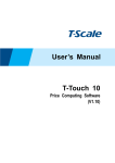
STM32-E407 development board USER’S MANUAL Revision E, December 2013 Designed by OLIMEX Ltd, 2012 All boards produced by Olimex LTD are ROHS compliant OLIMEX© 2013 STM32-E407 user's manual DISCLAIMER © 2013 Olimex Ltd. Olimex®, logo and combinations thereof, are registered trademarks of Olimex Ltd. Other product names may be trademarks of others and the rights belong to their respective owners. The information in this document is provided in connection with Olimex products. No license, express or implied or otherwise, to any intellectual property right is granted by this document or in connection with the sale of Olimex products. This work is licensed under the Creative Commons Attribution-ShareAlike 3.0 Unported License. To view a copy of this license, visit http://www.creativecommons.org/licenses/by-sa/3.0/. This hardware design by Olimex LTD is licensed under a Creative Commons Attribution-ShareAlike 3.0 Unported License. The software is released under GPL. It is possible that the pictures in this manual differ from the latest revision of the board. The product described in this document is subject to continuous development and improvements. All particulars of the product and its use contained in this document are given by OLIMEX in good faith. However all warranties implied or expressed including but not limited to implied warranties of merchantability or fitness for purpose are excluded. This document is intended only to assist the reader in the use of the product. OLIMEX Ltd. shall not be liable for any loss or damage arising from the use of any information in this document or any error or omission in such information or any incorrect use of the product. This evaluation board/kit is intended for use for engineering development, demonstration, or evaluation purposes only and is not considered by OLIMEX to be a finished end-product fit for general consumer use. Persons handling the product must have electronics training and observe good engineering practice standards. As such, the goods being provided are not intended to be complete in terms of required design-, marketing-, and/or manufacturing-related protective considerations, including product safety and environmental measures typically found in end products that incorporate such semiconductor components or circuit boards. Olimex currently deals with a variety of customers for products, and therefore our arrangement with the user is not exclusive. Olimex assumes no liability for applications assistance, customer product design, software performance, or infringement of patents or services described herein. THERE IS NO WARRANTY FOR THE DESIGN MATERIALS AND THE COMPONENTS USED TO CREATE STM32-E407. THEY ARE CONSIDERED SUITABLE ONLY FOR STM32-E407. Page 2 of 30 OLIMEX© 2013 STM32-E407 user's manual Table of Contents DISCLAIMER............................................................................................................. 2 CHAPTER 1 OVERVIEW......................................................................................... 5 1. Introduction to the chapter.......................................................................................................5 1.1 Features.....................................................................................................................................5 1.2 H407 or E407?..........................................................................................................................5 1.3 Target market and purpose of the board...............................................................................5 1.4 Organization.............................................................................................................................6 CHAPTER 2 SETTING UP THE STM32-E407 BOARD....................................... 7 2. Introduction to the chapter.......................................................................................................7 2.1 Electrostatic warning...............................................................................................................7 2.2 Requirements........................................................................................................................... 7 2.3 Powering the board..................................................................................................................8 2.4 Prebuilt software......................................................................................................................8 CHAPTER 3 STM32-E407 BOARD DESCRIPTION.............................................9 3. Introduction to the chapter.......................................................................................................9 3.1 Layout (top view).....................................................................................................................9 3.2 Layout (bottom view).............................................................................................................10 CHAPTER 4 THE STM32F407ZGT6 MICROCONTROLLER......................... 11 4. Introduction to the chapter..................................................................................................... 11 4.1 The STM32F407ZGT6 features............................................................................................11 CHAPTER 5 CONTROL CIRCUITY AND HARDWARE MODULES.............13 5. Introduction to the chapter.....................................................................................................13 5.1 Reset........................................................................................................................................13 5.2 Clocks......................................................................................................................................13 5.3 Power supply circuit.............................................................................................................. 13 CHAPTER 6 CONNECTORS AND PINOUT....................................................... 14 6. Introduction to the chapter.....................................................................................................14 6.1 JTAG/SWD debug................................................................................................................. 14 6.2 SD/MMC slot..........................................................................................................................14 6.3 UEXT module.........................................................................................................................15 6.4 USB_OTG1.............................................................................................................................15 6.5 USB_OTG2.............................................................................................................................16 6.6 LAN connector.......................................................................................................................17 6.7 Arduino/Maple platform.......................................................................................................17 6.8 20-pin connectors – PD – PE – PF - PG...............................................................................18 6.9 PWR Jack...............................................................................................................................19 6.10 Battery connector.................................................................................................................19 Page 3 of 30 OLIMEX© 2013 STM32-E407 user's manual 6.11 BOOT connector.................................................................................................................. 20 6.12 Jumper description..............................................................................................................20 6.12.1 PWR_SEL...................................................................................................................................................20 6.12.2 B1_1/B1_0 and B0_1/B0_0.........................................................................................................................20 6.12.3 R-T...............................................................................................................................................................21 6.12.4 3.3V_E......................................................................................................................................................... 21 6.12.5 AGND_E......................................................................................................................................................21 6.12.6 AREF_EN....................................................................................................................................................21 6.12.7 GPIO port jumpers....................................................................................................................................21 6.13 Additional hardware components...................................................................................... 21 CHAPTER 7 BLOCK DIAGRAM AND MEMORY.............................................23 7. Introduction to the chapter.....................................................................................................23 7.1 Processor family block diagram........................................................................................... 23 7.2 Physical memory map........................................................................................................... 24 CHAPTER 8 SCHEMATICS...................................................................................25 8. Introduction to the chapter.....................................................................................................25 8.1 Eagle schematic......................................................................................................................25 8.2 Physical dimensions...............................................................................................................27 CHAPTER 9 REVISION HISTORY AND SUPPORT..........................................28 9. Introduction to the chapter.....................................................................................................28 9.1 Document revision................................................................................................................. 28 9.2 Board's revision......................................................................................................................28 9.3 Useful web links and purchase codes.................................................................29 9.4 Product support..................................................................................................................... 30 Page 4 of 30 OLIMEX© 2013 STM32-E407 user's manual CHAPTER 1 OVERVIEW 1. Introduction to the chapter Thank you for choosing the STM32-E407 single board computer from Olimex! This document provides a user’s guide for the Olimex STM32-E407 board. As an overview, this chapter gives the scope of this document and lists the board’s features. The differences between the members of the STM32-E407 and STM32-H407 boards are mentioned. The document’s organization is then detailed. The STM32-E407 development board enables code development of applications running on the microcontroller STM32F407ZGT6, manufactured by STMicrocontrollers. 1.1 Features STM32F407ZGT6 Cortex-M4 210DMIPS, 1MB Flash, 196KB RAM, 3×12-bit 2.4 MSPS A/D, 2×12-bit D/A converters, USB OTG HS and USB OTG HS, Ethernet, 14 timers, 3 SPI, 3 I2C, Ethernet, 2 CANs, 3 12 bit ADCs, 2 12 bit DACs, 114 GPIOs, Camera interface JTAG connector with ARM 2x10 pin layout for programming/debugging UEXT connector 2 x USB-OTG SD-card Input DCDC power supply which allows operation from 6-16VDC source Power and User LEDs Reset and User buttons Arduino shield platform with provided headers 4 full 20-pin Ports with the external memory bus for add-on modules PCB: FR-4, 1.5 mm (0,062"), soldermask, silkscreen component print Dimensions: 10x76 mm (4''x3.40") 1.2 H407 or E407? The major difference between STM32-H407 and STM32-E407 is that the latter has built-in Ethernet (physical level transceiver Micrel - Micrel datasheet). STM32-E407 also features an extra USB-OTG and a number of SMD jumpers on the bottom which makes the control of the multiplexing pins easier. STM32-E407 has 2x USB-OTG both with a miniUSB interface. STM32H407 has 1x USB-OTG and 1x USB-HOST with the On-The-Go interfaced by miniUSB and the HOST by USB type A connector. If you need built-in Ethernet check the STM32-E407. 1.3 Target market and purpose of the board STM32-E407 is a development board featuring a powerful ARM Cortex-M4F microcontroller with the most important peripherals, interfaces and connectors mounted and ready to use. The board can be powered by a number of different sources, can be programmed via two different interfaces, has a Page 5 of 30 OLIMEX© 2013 STM32-E407 user's manual TON of GPIO pins available on a number of headers. The board's Arduino platform headers give another option for enthusiasts who wish to implement support for Arduino/Maple/Pinguino shields giving the board additional features altogether with the option to add Olimex extension modules on the OLIMEX UEXT. All of the above options make the board quite versatile and suitable for numerous tasks and situations. The power of ARM and the creativity of OLIMEX come at the best price and the wellknown quality. Every ARM enthusiast would see STM32-E407 as an interesting bargain and quite capable board for its low price. 1.4 Organization Each section in this document covers a separate topic, organized as follow: – Chapter 1 is an overview of the board usage and features – Chapter 2 provides a guide for quickly setting up the board – Chapter 3 contains the general board diagram and layout – Chapter 4 describes the component that is the heart of the board: the STM32F207ZET6 microcontroller – Chapter 5 is an explanation of the control circuitry associated with the microcontroller to reset. Also shows the clocks on the board – Chapter 6 covers the connector pinout, peripherals and jumper description – Chapter 7 shows the memory map – Chapter 8 provides the schematics – Chapter 9 contains the revision history, useful links and support information Page 6 of 30 OLIMEX© 2013 STM32-E407 user's manual CHAPTER 2 SETTING UP THE STM32-E407 BOARD 2. Introduction to the chapter This section helps you set up the STM32-E407 development board for the first time. Please consider first the electrostatic warning to avoid damaging the board, then discover the hardware and software required to operate the board. The procedure to power up the board is given, and a description of the default board behavior is detailed. 2.1 Electrostatic warning STM32-E407 is shipped in a protective anti-static package. The board must not be exposed to high electrostatic potentials. A grounding strap or similar protective device should be worn when handling the board. Avoid touching the component pins or any other metallic element. 2.2 Requirements In order to set up the STM32-E407 optimally, the following items are required: - JTAG or SWD interface programmer/debugger – can power the board and gives the ability to program/debug the board – to choose the correct programmer be sure that you are aware what software tools you are going to use when programming STM32-E407, and that the programmer supports STM32F407 processor. Additional components can be acquired in order to increase the functionality of the board: - External power supply - USB type “A” to USB type “mini” cable is required for bootlader - SD-card or extension UEXT modules are recommended but not required - 3.7V Battery - MOD-XXXX boards for additional features on the UEXT (RTC, TC, GSM, MP3, RS-485 among others) – note that you will have to implement the software setup between the boards - Arduino/Maple/Pinguino shields – every shield is hardware compatible with H407 but will not work out-of-the-box, software implementation should be considered Some of the suggested items can be purchased by Olimex, for instance: ARM-USB-TINY-H – high-speed OpenOCD ARM JTAG debugger ARM-USB-OCD-H – high-speed OpenOCD ARM JTAG debugger with buffer protection USB-MINI-CABLE USB mini to USB-A cable - USB mini to USB-A cable BATTERY-LIPO1400MAH – lithium-polymer battery 1400mAh USB-SERIAL-CABLE-F – easy way to connect the board to a computer terminal program using the BOOT pins SY0612E - power supply adapter 12V/0.5A for iMX233-STM32-E407 Page 7 of 30 OLIMEX© 2013 STM32-E407 user's manual 2.3 Powering the board The board is powered in one of the following ways: 1) by PWR jack, 2)by JTAG/SWD programmer (3)by USB-OTG. The PWR jack should be supplied from a 6V to 16V source with maximum current of 1A from the power jack. Without additional components and peripherals (no microSD card mounted, nothing connected to the USB, etc.) the typical consumption is 30mA @ 12V. For the European customers we sell an affordable power supply adapter 12V/0.5A - SY0612E. It is worth mentioning that the board can NOT be powered by the battery connector. The battery connected keeps some of the processor's functions remain intact during power down but it provides insufficient power for the board to operate properly. For example the RTC doesn't loose the values when there is a battery connected. 2.4 Prebuilt software Upon powering initially the board's red PWR LED and the green PWR LED should turn on. Page 8 of 30 OLIMEX© 2013 STM32-E407 user's manual CHAPTER 3 STM32-E407 BOARD DESCRIPTION 3. Introduction to the chapter Here you get acquainted with the main parts of the board. Note the names used on the board differ from the names used to describe them. For the actual names check the STM32-E407 board itself. The board comes with a bag with 4 headers for the Arduino/Maple/Pinguino platform which were left unsoldered in case you don't wish to use those environments or you don't plan on using shields. There is also a bag of 4 rubber pads which can be placed in the 4 corner holes of the board. That way the board will be safe from short-circuiting on the bottom if placed on low-resistance surface. The placement stability of the board will also increase. 3.1 Layout (top view) Page 9 of 30 OLIMEX© 2013 STM32-E407 user's manual Page 10 of 30 OLIMEX© 2013 STM32-E407 user's manual CHAPTER 4 THE STM32F407ZGT6 MICROCONTROLLER 4. Introduction to the chapter In this chapter is located the information about the heart of STM32-E407 – its Cortex-M4F microcontroller. The information is a modified version of the datasheet provided by its manufacturers from ST. 4.1 The STM32F407ZGT6 features Core: ARM 32-bit Cortex™-M4 CPU with FPU, Adaptive real-time accelerator (ART Accelerator™) allowing 0-wait state execution from Flash memory, frequency up to 168 MHz, memory protection unit, 210 DMIPS/1.25 DMIPS/MHz (Dhrystone 2.1), and DSP instructions Memories 1 Mbyte of Flash memory 192+4 Kbytes of SRAM including 64-Kbyte of CCM (core coupled memory) data RAM Flexible static memory controller supporting Compact Flash, SRAM, PSRAM, NOR and NAND memories LCD parallel interface, 8080/6800 modes Clock, reset and supply management 1.8 V to 3.6 V application supply and I/Os POR, PDR, PVD and BOR 4-to-26 MHz crystal oscillator Internal 16 MHz factory-trimmed RC (1% accuracy) 32 kHz oscillator for RTC with calibration Internal 32 kHz RC with calibration Sleep, Stop and Standby modes VBATsupply for RTC, 20×32 bit backup registers + optional 4 KB backup SRAM 3×12-bit, 2.4 MSPS A/D converters: 24 channels and 7.2 MSPS in triple interleaved mode 2×12-bit D/A converters General-purpose DMA: 16-stream DMA controller with FIFOs and burst support Up to 17 timers: up to twelve 16-bit and two 32-bit timers up to 168 MHz, each with up to 4 IC/OC/PWM or pulse counter and quadrature (incremental) encoder input Debug mode Serial wire debug (SWD) & JTAG interfaces Cortex-M4 Embedded Trace Macrocell™ 114 I/O ports with interrupt capability Up to 15 communication interfaces 3 × I2C interfaces (SMBus/PMBus) 4 USARTs/2 UARTs (10.5 Mbit/s, ISO 7816 interface, LIN, IrDA, modem control) 3 SPIs (37.5 Mbits/s), 2 with muxed full-duplex I2S to achieve audio class accuracy via internal audio PLL or external clock 2 × CAN interfaces (2.0B Active) Page 11 of 30 OLIMEX© 2013 STM32-E407 user's manual SDIO interface Advanced connectivity USB 2.0 full-speed device/host/OTG controller with on-chip PHY USB 2.0 high-speed/full-speed device/host/OTG controller with dedicated DMA, onchip full-speed PHY and ULPI 10/100 Ethernet MAC with dedicated DMA: supports IEEE 1588v2 hardware, MII/RMII 8- to 14-bit parallel camera interface up to 54 Mbytes/s True random number generator CRC calculation unit 96-bit unique ID RTC: subsecond accuracy, hardware calendar For comprehensive information on the microcontroller visit the ST’s web page for a datasheet. At the moment of writing the microcontroller datasheet can be found at the following link: http://www.st.com/internet/com/TECHNICAL_RESOURCES/TECHNICAL_LITERATURE/DAT ASHEET/DM00037051.pdf Page 12 of 30 OLIMEX© 2013 STM32-E407 user's manual CHAPTER 5 CONTROL CIRCUITY AND HARDWARE MODULES 5. Introduction to the chapter Here you can find information about reset circuit and quartz crystals locations, the power supply circuit is discussed. 5.1 Reset STM32-E407's reset circuit includes R5 (10KΩ), R6 (1 KΩ), C19 (100nF) and a RESET button. 5.2 Clocks There are two quartz crystals available on the board: 12 MHz quartz crystal Q1 is connected to pins 23 and 24 of the CORTEX-M4F processor. Quartz crystal Q2 is a 32 768Hz RTC (real-time clock) and is connected to pins 8 and 9. 5.3 Power supply circuit The power supply circuit of STM32-E407 allows flexible input supply from 6V to 16V direct current. This means a wide range of power supplies, adapters, converters are applicable. The maximum amperage the board can draw is 1A. Note that the Li-Po battery connector cannot be used to fully power the board. It's function is to give an option to save internal data if the board needs to be relocated. It will keep the RTC alive, for instance. If you have successfully powered the board the red PWR LED will turn on. Note that it is possible to have the PWR LED on even if there isn't enough power for proper operation of the board and all the peripherals currently connected. Page 13 of 30