1
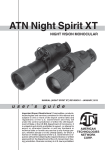
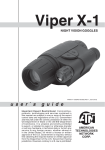
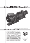
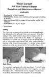
;-1
thEeral imaging weapon SIGH
u s e r ` s
g u i d e
Important Export Restrictions! Commodities, products, technologies and services contained in this manual
are subject to one or more of the export control laws and
regulations of the U.S. Government and they fall under the
control jurisdiction of either the US Department of State
or the US BIS-Department of Commerce. It is unlawful
and strictly prohibited to export, or attempt to export or
otherwise transfer or sell any hardware or technical data
or furnish any service to any foreign person, whether
SIERRA
abroad or in the United States, for which a license or writPACIFIC
ten approval of the U.S. Government is required, without
first obtaining the required license or written approval
INNOVATIONS
from the Department of the U.S. Government having
Cr.
jurisdiction. Diversion contrary to U.S. law is prohibited.
Focusing Ring
Eyepiece Diopter
Adjustment Ring
Mounting Rail
Lens
Rubber Eyecup
Objective Lens Cover
Switchboard
Universal Connector Unit
Battery Compartment Cover
Windage Adjustment
Lock Lever
Elevation Adjustment Ring
Fixation Screw
Clamping Knob
RCA Video/power adapter
Cau ti o n :
This product contains natural rubber latex which may cause allergic reactions
63, Corp. assumes no responsibility or liability for any errors or inaccuracies that may appear in this book.
©200 63, Corp. All right reserved.
features
• High resolution digital thermal scope
• Compact, light weight and durable housing
• High Quality optics
• Video output
• Video/Image polarity selection
• Waterproof
specification
Magnification.........................................................1,8X
Objective Focal Length.........................................25 mm
FOV.......................................................................11° x 8°
Focus Range.........................................................from 1m to infinity
Focus Adjustment.................................................Manual
Exit Pupil...............................................................14mm
Eye Relief..............................................................25mm
Windage and Elevation.........................................0.25 mil detent zeroing adjustments
Elevation adjustment range..................................50 mils
Windage adjustment range...................................45 mils
Detector Type........................................................Uncooled Microbolometer
Spectral Response...............................................7-14 μm
Pixels.....................................................................160 x 120
Pixel Size...............................................................30 x 30 μm
Angular Resolution, mrad.....................................1,2
Thermal Sensitivity...............................................< 0,1°C
Range to Detect a Human.....................................475 m
Output Format.......................................................Analog PAL / NTSC
Display..................................................................OLED matrix
Display Format......................................................SVGA, 852 x 600 pxl
Color......................................................................Monochrome
Digital ZOOM........................................................Fixed 2x (optional 5x)
Brightness Adjustment..........................................Manual
Contrast Adjustment.............................................Automatic
Power Supply........................................................2 x 3V, 123Atype
Start-Up Time........................................................< 3 sec
Operating Time w/one battery pack......................4 hrs
External Power Supply..........................................DC 6V, 500 mA
Operating Temperature Range.............................from -20°C to +50°C
Waterproof............................................................Yes, up to 10m submersion
Dimensions...........................................................195 x 81 x 105 mm (w/ weapon mount)
..............................................................................118 x 81 x 52 mm (w/o weapon mount)
Weight (w/batteries)..............................................0,74 kg
63,reserves the right to change the above specifications at any time without notice
application
The ; is a compact dual purpose thermal imaging weapon sight and monocular.
This ; is built around state of the art uncooled thermal imaging technology, highly integrated
DSP-based electronics and a compact, light weight system.
The ; thermal weapon sight provides excellent image quality through total darkness, fog, smoke
and most visual obscurants.
The ; is an ideal product for Border Patrol Officers, Sport Shooting Enthusiasts, Private Protection, Police SWAT and Special Operations.63,
2
operation
Insert the two Lithium batteries (123A type) into the unit according to the polarity indications on the battery compartment. Press
the ON/OFF button to turn the monocular on. Remove the lens
cap.
Adjust the proper eyepiece diopter and objective lens focusing.
The rotation of the Focusing Ring changes the position of the
objective lens in respect of the receiver focal plane array. In this
way the operator can adjust the unit in order to see the targets at
various ranges with the same good contrast.
Cover protects the objective assembly from mechanical damage.
The operator can adjust the eyepiece diopter of the monocular for his/her own eyesight by rotating
Eyepiece Diopter Adjustment Ring.
Eyecup provides for the comfortable eye position and for the prevention of flash reflections onto the
operator’s face which is critical in the field and tactical activities.
Select the desired operation mode by pressing the switchboard
buttons.
With the «ZOOM» button you can activate a gradual adjustment
of the digital zoom preset in the monocular adjustments.
The «POLARITY» button switches the direct display mode into
the reverse one, i.e. from hot-white/cold-black into hot-black/
cold-white mode.
Each short push of the buttons «BRIGHTNESS +» or «BRIGHTNESS –» raises or lowers the display brightness, correspondingly, in stepwise way.
To turn the monocular off press the ON/OFF button.
mounting
CAUTION: It is recommended that the eyecup be replaced with the eyeguard during weapon-mounted
use.
The ; mount based on ELCAN mounting assemblies. ELCAN mounting assemblies are commercially available to O.E.M. producers of optical and electro-optical sighting systems or wherever a
mil-spec attachment and zeroing mechanism is required. All ELCAN Mount assemblies attach directly
to MIL-STD-1913 rails or receivers. The mount incorporates generous elevation and azimuth adjustment and is produced in ballistic calibrations for 5.56 NATO. ELCAN mount assemblies, when installed
on a weapon sight are designed to withstand a drop of 1.5 metres onto concrete while attached to an
8kg weapon.
The ; mount requires Picatinney or slotted weaver style base for attachment to the firearm. It is
important to keep from over tightening the both the rail screws and the ring screws. The large bearing
surface on both allows minimal torque on the screws. It is recommended to grip the short end of an
allen wrench to apply torque so that torque is minimized on the ring screws, then add another 1/8 turn
utilizing the long end of the wrench. The mounting wing nuts can be tightened adequately using a pair
of needle nosed pliers.
Once mounted on the rifle install the scope onto the mount.
1. Loosen the clamping knob on the weapon mount. Position the monocular mount on the weapon’s
mounting rail, adjust the fore/aft position of the monocular as necessary by loosening the clamping
knob and repositioning the weapon mount on the rail. Tighten by turning the clamping knob.
2. Align the monocular and the weapon mount. Slide the monocular rearwards until the alignment boss
aligns with the alignment groove on the weapon mount. Push until the monocular locks into the weapon
mount.
Using the ; mount impact can and should be used to for initial sighting in or zero. Ideally this
should be done at 200 yards or 100 yards if the ballistic curve for your chosen ammo is known.
Referring to Figure use the following sequence:
1. Check the windage for zero. If the crosshair is not centered adjust it by rotating the a centric inserts
via the following method:
Use the slot milled into the top half of each ring to access the holes drilled thru the insert). Move the
inserts radially to achieve the above described scope picture by inserting a round rod into the holes
drilled in the insert. The shank (blunt end) of a 9/64 drill works perfectly. When the reticle is centered,
3
tighten the ring screws exerting torque on the Horizontal Adjuster (D)
short end of the supplied allen wrench. It is not
necessary to use the leverage of the long arm to
tighten the screws any more than an additional
1/8 turn.
2. Set Ballistic Cam (BC) “A” on position 1 (100
Clamping
Yards) by locking the BC Lock Lever (BCL) “C”
Knob
in the down position and turning it full CW as
Lock
Lever
(C)
viewed from above.
Vertical Adjuster (B)
Ballistic Cam (A)
3. Lock out BC by placing the BC Lock “C” in
the up position and run the mount’s Main Vertical Adjuster (MVA) “B” to its lowest setting by turning it full CW, also. The mount is now positioned for
initial sight in at 100 yards.
4. Sight scope in for 100 yard zero utilizing only the mounts adjusters “B” and “D”.
Absolute zero may not be attainable with “B” due to coarseness of clicks, but get as close as possible.
USE
Properly used your scope’s reticle will now remain centered on its optical axis if the following shooting
procedure is used.
Normally only the vertical or elevation fine adjuster (internal scope) is used to fine-tune individual sighting. Windage is best done with reticle assisted “hold off”. The reason for this is that it is relatively easy
to remember elevation adjustments, but somewhat harder to keep track of windage.
Out to 200 Yards
Engage BCL “C” and use the integral Ballistic Cam to adjust elevation zero in 100 yard increments.
Beyond 200 Yards
Disengage BCL “C” and use LR Mount’s MVA “B” to acquire range.
Mount Specifications
Base Requirement
MIL-STD-1913 "Picatinny Rail"
Base attachment
clamping foot with metal wing nuts
Windage and Elevation
0.25 mil detent zeroing adjustments
Elevation adjustment range
50 mils
Windage adjustment range
45 mils
Ballistic Compensation
5.56 NATO 62gr FMJ: 200-800m, 100m increments
Instrument attachment
120 degree V-block with two M5x0.8mm pitch hold-down capscrews, 38mm spacing on long-axis centerline
Durability
Designed to withstand a drop of 1.5 metres onto concrete while
attached to an 8 kg weapon
video output
The monocular incorporates a sealed Connector used for video transmission and to connect external power sources. The
package of the ; includes external connection RCA
Video/power adapter. This adapter attaches the monocular to
the video facilities for video recording or video transmission
to the external display, though at the same time it accepts the
external power supply.
IMPORTANT: When the unit is to be powered with external sources, first make sure the batteries have been taken out.
Video
Connector
External Power
Supply Connector
4
external power source
IMPORTANT: When the unit is to be powered with external sources, first make sure the batteries have
been taken out.
To connect an external power source you can use any of the cables of the monocular package. As an
external power source, a standard network controller with outer voltage of 6V and current of over 0.5A
can be applied.
Remove the protective cover off the connector input and attach the cable. To connect an external
source, we recommend you to use a 6mm standard double-pole socket in the way the positive contact
is the central contact.
warnings and cautions
IMPORTANT!
DO NOT DISASSEMBLE THE MONOCULAR.
KEEP YOUR ; SAFE FROM OPERATIONAL AND TRANSPORTATION IMPACTS.
WAITING FOR ONE HOUR BEFORE YOU SWITCH THE MONOCULAR ON IS HIGHLY RECOMMENDABLE AFTER YOU BRING IT INTO THE WARM ROOM FROM THE COLDER OUTSIDE.
WHEN YOU DO NOT INTEND TO OPERATE YOUR MONOCULAR FOR 10 FOLLOWING DAYS WE
ADVISE YOU TO TAKE THE BATTERY OUT OF THE BATTERY COMPARTMENT.
PROVIDE FOR TIMELY SERVICE MAINTENANCE OF THE UNIT.
If you use the rubber eyecaps for a long period of time, you may suffer skin inflammation. If you
develop any symptoms, consult a doctor immediately.
troubleshooting
Q: The image is absent on the screen of goggles.
S: The batteries are discharged. Replace the batteries.
Q: The brightness of the image on the screen is low.
S: The batteries has a low voltage. Replace the batteries.
5
6
For customer service and technical support, please contact
6LHUUD3DFLILF,QQRYDWLRQV&RUS
S7HQD\D :D\/DV9HJDV, 19 Phone: ; fax: www.[RUJ
©2009 SPI Corp.