1
Prodaja in zastopa:
Materm d.o.o. Morje, morska cesta 6, 2313 Fram
tel: 02 608 90 10, www.materm.si
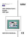
HMI OPERATOR’S
PANEL
HMI type
SERVICE MANUAL
1
Contents
1
Application .......................................................................................................................... 2
2
Panel set .............................................................................................................................. 3
3
Basic requirements and operational safety...................................................................... 3
4
Installation ........................................................................................................................... 3
4.1
Dimensions and mounting .............................................................................................. 4
4.1.1 Dimensions of HMI 450 panel .................................................................................. 4
4.1.2 Dimensions of HMI 730 / HMI 750 panel .................................................................. 5
4.1.3 Dimensions of HMI 1050 panel ................................................................................ 6
4.1.4 Dimensions of HMI 1550 panel ................................................................................ 7
4.1.5 Mounting method ..................................................................................................... 8
4.2 Connections .................................................................................................................... 9
5
6
7
4.2.1 Power supply............................................................................................................ 9
4.2.2 Interfaces ................................................................................................................. 9
Panel settings ................................................................................................................... 12
5.1
Starting ......................................................................................................................... 12
5.2
“Run” function ............................................................................................................... 13
5.3
“Project” function........................................................................................................... 13
5.4
„Instrument” function ..................................................................................................... 14
5.5
“Touch Calibrate” function ............................................................................................. 14
5.6
“System Info” function ................................................................................................... 15
5.7
Resetting the panel (reset)............................................................................................ 15
Software toolkit for PC ..................................................................................................... 16
6.1
System requirements .................................................................................................... 17
6.2
Installation..................................................................................................................... 17
Description of selected functions of Panel Studio ........................................................ 18
7.1
Opening existing projects.............................................................................................. 18
7.2
Creating a new project .................................................................................................. 19
7.3
Adding ModbusTCP/IP connection ............................................................................... 25
7.4
Sending project to the panel ......................................................................................... 27
8
Technical specification .................................................................................................... 28
9
Order codes ...................................................................................................................... 29
User’s manual
1
2
Application
The Operator Panel is one of the tools designed for process operators. The panel is a
graphical interface between its user and the process. It provides the user with the following
functions: control, monitoring, visualization and process management. The operator using the
panel has the ability to enter data and control devices via the touch screen. The device is
designed to work with PLCs, controllers, transmitters and other devices.
The Operator Panel ensures simple control of a process, e.g. by selecting a predefined set
of parameter settings, entering values from the keyboard , generating alarms and warnings, and
creating reports that include important parameters changes during the process, e.g. for the
quality management department of a plant. Advanced features of the device, such as
animations, trends, data acquisition, logging, and securing data facilitate operator's work and
provide information for optimizing the process. Advanced visualization and a wide range of
functions also help to minimize operational errors, improving the process quality.
A control algorithm for the panel is created on a PC for specific solutions of the control
system and then it is sent to the panel via Ethernet connection or downloaded from USB drive.
The algorithm is created with “Panel Studio” - an effective programming tool, which does not
require knowledge of any programming language and operates on any PC with Windows XP /
VISTA / 7/ 8. This software is equipped with communication drivers for many devices and an
extensive library of functional modules that facilitate configuring functions of the panel, fault
diagnostics and designing dialogues with the user. An application algorithm is created by
inserting prepared library objects into design sheets and setting parameters of these objects in
accordance with requirements.
User’s manual
2
3
Panel set
The panel set contains:
•
HMI Operator’s Panel
•
Fixing brackets:
•
HMI 450
•
HMI 730/HMI 750
•
HMI 1050
•
HMI 1550
•
Users’ manual
•
guarantee card
•
installation CD for „Panel Studio” software
3
1 pc
4 pcs
6 pcs
10 pcs
12 pcs
1 pc
1 pc
1 pc
Basic requirements and operational safety
Safety considerations:
• Assembly and installation of electrical connections/wiring should be performed by a person
with the required permissions for installation of electrical equipment. .
• Before activating the panel, check the correctness of connections.
• The panel meets the requirements of electromagnetic compatibility in industrial environment.
• The product is not authorized for use in life-support systems, aircraft navigation and military
systems and in other systems where its failure may be life threatening or lead to disaster.
4
Installation
Guidelines:
1.
The device is designed for indoor use.
2.
HMI panel should be installed in a suitable enclosure / panel / cabinet.
3.
Avoid exposing panel screen to direct sunlight.
4.
Avoid installing the panel in areas of high vibration, close moving parts.
5.
Avoid installing the panel in the proximity of devices that emit strong radiation / noise, such
as motors, transformers, frequency converters, inverters, UPS, etc.
6.
Avoid installing the panel in areas exposed to vapours, gases, oils, greases, chemicals, etc.
7.
Install the panel in an opening, which is in accordance with its specification, using all
mounting brackets provided.
8.
Ensure adequate ventilation in order to avoid exceeding the allowable operating
temperature indicated in the product specifications.
9.
Improper installation will void the guarantee.
User’s manual
4
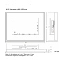
4.1 Dimensions and mounting
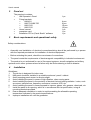
4.1.1 Dimensions of HMI 450 panel
Note: All dimensions are in mm. Tolerance +/- 1 mm
Dimensions of opening for the panel: 123+1 X 99+1
User’s manual
5
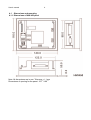
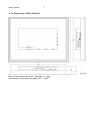
4.1.2 Dimensions of HMI 730 / HMI 750 panel
Note: All dimensions are in mm. Tolerance +/- 1 mm
Dimensions of opening for the panel: 197+1 X 141+1
User’s manual
6
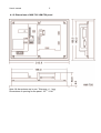
4.1.3 Dimensions of HMI 1050 panel
Note: All dimensions are in mm. Tolerance +/- 1 mm
Dimensions of opening for the panel: 310+1 X 248+1
User’s manual
7
4.1.4 Dimensions of HMI 1550 panel
Note: All dimensions are in mm. Tolerance +/- 1 mm
Dimensions of opening for the panel: 367+1 X 289+1
User’s manual
8
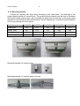
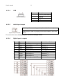
4.1.5 Mounting method
Prepare the opening with dimensions according to the table below. The thickness of the
board material should not exceed 6 mm. The panel must be inserted from the front of the board
with disconnected power supply. After inserting the panel into the opening, fix the panel using
brackets on the back plate (see photos below). Avoid overtighting or uneven fixing the brackets,
as this may damage the touch panel.
Model
HMI 450
+1
HMI 730
197
+1
HMI 750
HMI 1050
367+1
123
Height [mm]
99+1
141+1
141+1
248+1
289+1
Depth [mm]
51
51
51
50
50
Number of brackets
4
6
6
10
12
Mounting brackets for metal for plastic housing
310
HMI 1550
+1
Width [mm]
Mounting brackets for metal housing
197
+1
User’s manual
9
4.2 Connections
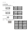
4.2.1 Power supply
The following options are available.
AC power supply, 90-250 V AC, 47-63 Hz
Terminal
Description
Grounding
1
2
N
3
L
Terminal
Description
DC power supply, 11-36 V DC
Grounding
1
2
DC -
3
DC +
DC power supply, 11-36 V DC (only for HMI 450)
Terminal
Description
1
DC +
2
DC -
4.2.2 Interfaces
4.2.2.1
COM1 port, DB9 male (RS232C)
Pin
Signal
Input / Output
1
DCD
Output
2
RD
Input
3
TD
Output
4
DTR
Output
5
SG
6
DSR
Input
7
RTS
Output
8
CTS
Input
9
RI
Input
User’s manual
4.2.2.2
4.2.2.3
10
COM2 port, DB25 female (RS232C/RS422/RS485)
Pin
Signal
Input / Output
Type
1
FG
-
-
2
TD
Output
RS232C
3
RD
Input
RS232C
4
RTS
Output
RS232C
5
CTS
Input
RS232C
6
DSR
Input
RS232C
7
SG
-
5V-/RS232C
8
DCD
Output
RS232C
9
-
-
-
10
-
-
-
11
-
-
-
12
TXDA
Output
RS422/RS485
13
TXDB
Output
RS422/RS485
14
RTSA
Output
RS422
15
RTSB
Output
RS422
16
-
-
-
17
-
-
-
18
CTSA
Input
RS422
19
CTSB
Input
RS422
20
DTR
Output
RS232C
21
5V+
Output
22
RI
Input
RS232C
23
-
-
-
24
RXDA
Input
RS422
25
RXDB
Input
RS422
Ethernet
RJ45 connection
Ethernet 10/100 Mbps
Pin
Description
1
Transmission (TX+)
2
Transmission (TX-)
3
Reception (RX+)
4
Not connected
5
Not connected
6
Reception (RX-)
7
Not connected
8
Not connected
User’s manual
4.2.2.4
11
USB
USB connection
4.2.2.5
Pin
Description
1
+ 5V DC (max 100mA)
2
USB-DN
3
USB-DP
4
GND
Audio input /output
Audio input for connecting a microphone (for future use)
Audio output. Used for playing sound files related to an Event /
Alarm
Input / output socket
For connection use a headphone jack: ø3.5mm and length 14mm.
4.2.2.6
Digital inputs / outputs
Pin
Symbol
Description
Label in Panel Studio
1
24V +
+ 24V DC power supply
2
EIN1
Digital input 1
SystemDI_1
3
EIN2
Digital input 2
SystemDI_2
4
EIN3
Digital input 3
SystemDI_3
5
ALM1
Digital output 1
SystemDO_1
6
ALM2
Digital output 2
SystemDO_2
7
ALM3
Digital output 3
SystemDO_3
8
GND
Neutral (ground) 0V DC
User’s manual
12
The digital input can be controlled by closing the switch or using 24 V logic signal. The input is
active when the switch is closed, or when the input pin is supplied with 24 V voltage.
L1, L2 and L3 may be resistive or inductive load such as a buzzer or relay.
Note: The sum of the currents in L1, L2 and L3 circuits must be less than 10mA.
VO1, VO2, VP3 are digital outputs in 24V standard for operation with PLC’s or external devices
P3 are digital outputs in 24V standard for operation with PLC’s or external devices.
5
5.1
Panel settings
Starting
The panel is factory-equipped with WinCE 6.0 operating system and "Control Center"
firmware for panel management (configuring its settings). The firmware may be updated during
its later operation by user via a USB stick. Information about the version of the firmware is
available in the "System Info" function described later in this document. To obtain the latest
version of the firmware, please contact the product dealer.
The firmware is designed primarily for transferring the application, its start-up; calibrating the
touch-screen; setting the clock, IP address, beeper volume, screen brightness, screen-saver
time and screen orientation.
After starting, the panel displays the following screen.
User’s manual
13
5.2
“Run” function
This function is used to run applications in the panel. After sending an application
(algorithm) from the PC via Ethernet or uploading it from USB memory, pressing the "Run"
function starts the application in the panel.
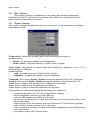
5.3 “Project” function
This function manages the application (project) in the panel. It may be selected via dialogue
field presented below
“Power action” field defines the panel action after switching power supply on.
Available options:
• Project – the panel automatically runs the application,
• Control Center – the panel remains in “Control Center” program.
“Load action” field defines the panel action after sending the application from a PC or
downloading it for USB drive.
Available options:
•
Load – the panel remains in “Control Center” program,
•
Load&Run – the panel automatically runs the application.
“Download” field is used to Enable / Disable sending the application from a PC to the panel.
“Upload” field is used to Enable / Disable reading the application from the panel by a PC
“Load” button is used to load application from USB drive into the panel.
“Save” button is used to save the application on USB drive.
“Clear” button is used to remove the application from the panel.
The procedure for manual downloading the application from USB drive:
• prepare the application on a PC, using “Panel Studio” software
• save the application from the PC to the USB drive,
• insert the USB drive into the USB slot in the panel
• tap the touch-screen with your finger and with finger on the touch-screen switch on the
panel power supply ,
• keep the finger on the touch-screen until the initial screen of “Control Center” appears
• select "Project" function and then click "Load" button,
• in the next window, browse to the path of the project (application) on the USB drive and
click "Load" button,
• if you want to resign, click "Cancel" button.
User’s manual
14
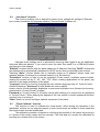
5.4
„Instrument” function
This function enables user to adjust the system clock, change the settings of Ethernet
port, screen orientation and language used by “Control Center” software etc.
Changed clock settings result in permanent removing data logged-in by the application
(historical data and alarms). If you want to save the data, then send it to a USB drive before
changing the clock settings.
"Ethernet” function defines how the panel obtains an IP address. Selecting "DHCP" means that
the address will be automatically assigned by DHCP server when connecting to the network.
Selecting "Static" function allows user to manually assign an IP address, subnet mask, and
gateway address for access to an external network (e.g. the Internet).
"Orientation" function is used to set the orientation of the screen. Available options include:
rotating the screen left by 0º, 90º, 180º, 270º. When creating applications for the panel, pay
attention to the target orientation of the panel.
"Language" function is used for changing the user interface language only for “Control Center”.
Advanced settings ("Advanced" button) enable the user to adjust:
buzzer volume, screen backlight brightness, screen saver activation time (0-blocks the function),
passwords for “Control Center” program
Password for “Control Center” is a number, which (after defining it) is required for all operations
in “Control Center”. When defining the password, the user enters a numeric password and then
confirms it by re-entering it.
"Other" button is used to configure optional equipment of the panel.
5.5
“Touch Calibrate” function
This function is used to calibrate the touch-screen. When during the operation of the
application, buttons do not respond properly or their touch areas are shifted it could mean that
the touch-screen must be recalibrated.
The calibration procedure is based on confirming the position of the marker by touching it
in 5 areas of the screen (centre and four corners). The final step is to accept the calibration by
touching any chosen area of the screen.
User’s manual
15
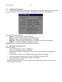
5.6
“System Info” function
The function displays information about used data and available disk space. It also allows
the user to update “Control Center” program. The displayed window is presented below.
Presented information includes:
• Version – current version of Control Center,
• Flash – status of used/available internal flash memory,
• SD card – status of used/available space on SD card,
• USB disk – status of used/available space on USB disk connected to the panel,
• IP/MAC – IP and MAC address of Ethernet interface.
“Update” button is used for updating Control Center firmware.
5.7 Resetting the panel (reset)
Reset procedure:
• connect (short) pins 2 and 3 in COM2 port,
• then turn on the power supply of the panel,
• after pop-up window with message “Do you want to format flash disk?” is displayed,
select „Yes”,
• another pop-up window will be displayed indicating further proceedings,
• remove connection between pins 2 and 3 in COM2 port and press “OK”,
• turn off and then turn on the power supply of the panel,
• calibrate the touch-screen.
Reset procedure will clear the entire contents of the internal flash memory and restore the
device to factory settings.
User’s manual
6
16
Software toolkit for PC
The toolkit includes:
• Panel Studio for creating and editing applications for the panel,
• Historical Viewer to view panel historical data on a PC.
“Panel Studio” is designed to create applications for the panel in order to expand
operator interface in industrial applications. Using the control panel, the operator may
communicate with many different devices using OPC servers that support various protocols via
serial port and Ethernet.
“Panel Studio” may be used to expand operator interface by operating various objects
with the following functions:
• controlling the elements of the object,
• displaying current status of pumps, motors, etc.
• displaying process parameters such as temperature, pressure, etc.,
• visualization of the process using bar graphs, trends, historical trends, gauges, digital
boxes, etc.
• activating alarms and managing current and historical alarms,
• recipe, script management,
• animation of objects by controlling their visibility, flashing, horizontal and vertical offset,
etc.
• implementing schedules,
• data logging, security features, supporting multiple languages
Historical Viewer is a tool for viewing historical data collected by the panel. Panel data
are stored in the internal memory or on a SD card in a secure format. This data may be stored
on a USB drive or imported to a PC by Historical Viewer and then archived in a form chosen by
the user.
The software has the following objects and features:
• historical trends,
• a list of historical alarms and events
• data tables,
• searching data with various search criteria: time, period, event, label and notes
• vertical and horizontal displaying of trends
• trend zooming in/out, scales,
• exporting data to cvs files,
• printing: trends, lists of alarms / events, data tables
Detailed instructions for software toolkit are in the help files and in digital documentation in the
form of PDF files
User’s manual
17
6.1 System requirements
Requirements:
• PC with 1GHz processor,
• 1GB of RAM (minimum), 2GB preferred
• 500 MB of available hard disk space (at least 20% free space on the hard drive, an
error message is generated below 10%)
• Network Interface Card with RJ 45 connection
• RS232 optional serial port, RS485/RS232 converter for on-line tests, if required,
• USB host port to operate USB flash drives,
• screen resolution better than 1024x768 (for projects on HMI 1050 and 1550 panels),
• operating system: Windows XP/Vista/7/8, Windows 2003 Server.
6.2
Installation
After starting the installer from the DVD or other media, follow its instructions.
Install the following components:
•
Microsoft Installer V3.1,
•
Microsoft.Net framework V3.5 SP1,
•
Panel Studio,
•
OPC server,
•
Demo projects,
•
Historical viewer,
•
Remote viewer.
User’s manual
7
18
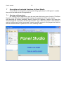
Description of selected functions of Panel Studio
“Panel Studio” is designed for creating and editing applications for HMI panel. It enables
the user to test and transfer the applications.
7.1
Opening existing projects
An existing project (application) may be read and edited using menu function "File/Open
Project" or the "Open an existing project" located in the central part of the main window.
After selecting the function message "Select a Project File" appears to select a file, where the
desired project file is stored (a file with the extension ".prj"). When the project is downloaded, it
may be modified and further developed. Projects recently opened in the program are listed in
the main window written in plain text or in "File / Recently" menu.
User’s manual
19
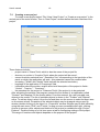
7.2
Creating a new project
To create a new project select “File / New / New Project” or “Create a new project” in the
central part of the main window. Then in “New Project” window define the basic features of the
project.
These features include:
– project name in "Name" field, which is also the name of the project file
– directory on a drive in "Location" field, where the project will be saved ,
– screen resolution selected from " Resolution" list, corresponding to the resolution of the
panel on which the application will work - this parameter cannot be modified after
accepting ("Width" and "Height" fields indicate the selected resolution),
– language of the application in "Language" field,
– information about the author, version and a brief description of the project in fields :
"Author" , "Version ", " Comment ",
– the password for the project in "Password" field, if the project is to be protected.
After accepting the settings, the program creates the first screen of an application called
"Screen1” and displays it in the screen editor. From this moment, the user may add new
objects to the screen. The list of available objects is shown in the "Toolbox" and "Objects”
menu. To add an object, select it from the list and then use the mouse to select its target area
on the screen where. Properties of the selected object may be changed using a pop-up
window (double-clicking on the object) or „Properties" window. Objects may be also edited by
using the main menu ("Edit” and "Format ) or pop-up menu accessible after right -clicking.
Access to screens, other objects and features of the project is available through „Project
Explorer". Double-clicking on a list item opens a tab for configuring settings of the project.
The range of functions and objects depends on the purpose of the project.
User’s manual
20
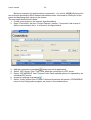
Below an example of a simple project is presented – it is used in MODBUS protocol for
two read-outs provided by ND20 network parameters meter connected to COM2 port of the
panel and displaying their values on the screen.
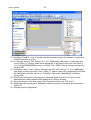
The next steps should be as follows:
1. Create a new project in the manner described above.
2. Open "Connection" tab from "Project Explorer" window. "Connection" tab is used to
define communication links - it is shown in the figure below
button and set its parameters.
3. Add the connection by pressing
4. Select “OPC Server” from “Type” field. Mark the connection by OPC server.
5. Select “OPCMODBUS” from “Protocol” field. Each available protocol is operated by an
individual OPC server.
6. Accept the settings by pressing
.
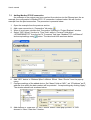
7. Select “Config” button from “Protocol” field and this action will transfer OPCMODBUS
server to the configuration program, as shown in the window below.
User’s manual
21
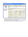
8. Right-click “Address Space "in the list on the left side of the window and selecting "New"
in the pop-up menu followed by "Port". Parameters for serial port "Port 2" are displayed,
as shown above. After entering accept them using "Apply".
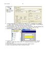
9. Select "New" from the pop-up menu of "Port2" and then "Device." The configuration will
be added to the device. Device parameters are displayed, as shown below.
User’s manual
22
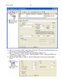
10. Add “U1” to element “ND20” using “New / Data Item” with element settings as shown on
the fig. below, accept it using "Apply" button.
11. Add “I1” element to “ND20” with the following settings” Name”=”I1”,
“Description”=”Current of L1 phase”, “Starting address:”=7003, “Data type”=REAL and
accept it using "Apply" button.
12. Set “Word swap” field as “Ideal” in “Device Parameters” and accept it using "Apply"
button.
User’s manual
23
13. Close the program in “File / Exit” menu. It will update the Tag database in the current
project.
14. Return to „Panel Studio”.
15. Select „Screen1” tab in the edition window.
16. Select “Basic Objects” element in “Toolbox” window
17. Select “TextBox” element from “Basic Objects” list and drag it to “Screen1” window into
the desired location.
18. Drag “Label” element to “Screen1” window. It should look as shown in fig. below.
User’s manual
24
19. Configure “TextBox” control. Double click the element to enter “Properties” or select this
function from pop-up menu.
20. In “General” tab set “Text” field as ”U1”. For “TagBinding” field select or enter tag name
“Port2_ND20_U1” and its value will be displayed in this field (in this case the value is
“U1” read by OPCMODBUS server via “Port2” from “ND20” device). Accept changes by
clicking “OK”.
21. Configure “Label” control. Select “General” tag. Set “Text” field as ”I1”. For „TagBinding”
field select or enter tag name “Port2_ND20_I1” and its value will be displayed in this field.
Set “BackColor” field as “yellow”. In “TextAlign” field select “MiddleRight”. Accept by
clicking “OK”.
22. Check the correctness of the project by selecting “Build” function in “Project” menu.
Messages and check results will be displayed in “Output” window.
23. Save the project on the disk using “Save Project” function from “File” menu .
24. Send the project to the panel. Methods for project transfer to the panel are described in
section 27.
25. End the project configuration.
User’s manual
25
7.3
Adding ModbusTCP/IP connection
An extension of the project may be a read-out from devices via the Ethernet port. As an
example, the configuration of ModbusTCP / IP connection is shown below. We will use the
example from the previous section. The procedure is presents below.
1. Open the example from the previous section.
.
2. Add a new connection in “Connection” tab using
3. When it is not open, double-click “Connection” element in “Project Explorer” window.
4. Select “OPC Server” function in “Type” field, while in “Protocol” field select
„OPCMODBUSTCP” from the list. In “Comment” field type “Modbus TCP via Ethernet”
and accept settings using
button. The tab should look as shown below.
5. Go to connection configuration by clicking „Config”.
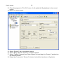
6. Add “ND1” device to “Address Space” element. Select “New / Device” from the pop-up
menu.
7. Configure settings of the added device. Set “Name” field as “ND1”, set “IP Address” as IP
address from which the data readout will be provided. . Accept settings by clicking “Apply”.
The window should look as shown below.
8. Add element of “Data Item:’ to „ND1” device. Select it from pop-up menu of ”ND1
element in “New / Data Item” function.
User’s manual
26
9. Configure parameters of the element. Set “Name” as “U1”, “Description” as “Voltage of
L1” phase, “Starting address:” field as 4001, “Data type” field as “REAL”. Accept settings
by clicking “Apply”. The window should look as shown below.
10. Close the program using “File / Exit” and return to “Panel Studio”. The label database will
be updated and “U1” element will be visible in “Panel Studio” a “ND1_U1” tag.
11. Add elements of „TextBox” type to “Screen1” in “Screen1” tab.
12. Configure added element (double-click it). Select “General” tab: set “Text” field as
„ND1_U1”, “TagBinding” field as “ND1_U1”. Accept the settings by clicking “OK”.
13. Save the project.
14. Check the correctness of the project using “Project / Build” function.
15. Send it to the panel using “Project / Download” function
User’s manual
27
7.4 Sending project to the panel
After creating the application (project) and its functional checking, it may be send to the panel.
Program provides the following options for sending the application to the panel:
•
via Ethernet connection by sending the application from the program,
•
using USB connection in the panel and a removable disk, after saving the application
from the hard drive to the disk.
Procedure of saving the application using Ethernet connection :
•
after creating the application, build the project (use "Project / Build" function) and make
sure that there are no compilation errors,
•
provide connection of the panel and PC to the Ethernet network,
•
check the IP address of the panel in "System Info" of the panel menu
•
in “Panel Studio” activate "File / Environment" menu
•
in "Environment" pup-up menu select "Download and Upload" group
•
in "Connection" field select "Ethernet" and enter the IP address of the panel in "IP" field
and accept it by clicking "OK"
•
then in "Project" menu select "Download", this will result in sending the application to the
panel
•
Procedure of saving the application using USB drive:
•
after creating the application, build the project (use "Project / Build" function) and make
sure that there are no compilation errors,
•
connect USB flash drive to your computer via USB port,
•
in “Studio Panel” select "File / Environment" menu
•
in "Environment" pup-up menu select "Download and Upload" group
•
in "Connection" field select "Removable disk" and accept it by clicking "OK"
•
then in "Project" menu select "Download", it will send the application to the USB drive,
•
insert the USB drive into the USB slot of the panel
•
switch the panel on,
•
select "Project" function and then click "Load", select the path to the project file and then
press "Load" button next to the path selection field,
•
this will transfer the application from a portable USB drive to the panel.
User’s manual
8
28
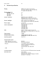
Technical specification
Display
Display dimensions
HMI 450
HMI 730, HMI 750
HMI 1050
HMI 1550
65535 colours with a touch-screen
TFT Wide (HMI 450, HMI 730, HMI 750)
TFT (HMI 1050, HMI 1550)
4.3 ”
7”
10 ”
15’’
Screen resolution
480x272 pixels (for HMI 450)
800x480 pixels (for HMI 730, HMI 750)
1024x768 pixels (for HMI 1050, HMI 1550)
Screen backlight
LED, operation time 50 000 hours
LED, operation time 30 000 hours (HMI 450)
Power supply
11-36 V DC
90-250V AC (except HMI 450)
Power consumption
10W
12W
13W
15W
27W
CPU
ARM11, 533MHz (HMI 450, HMI 730)
ARM Cortex-A8, 667MHz (HMI 750, HMI 1050,
HMI 1550)
Flash memory
128MB
SDRAM (RAM) memory
128MB (HMI 450, HMI 730)
256MB (HMI 750, HMI 1050, HMI 1550)
Operating system
WinCE 6.0
(HMI 450)
(HMI 730)
(HMI 750)
(HMI 1050)
(HMI 1550)
Communication ports
- COM1, DB9 male connection
RS232C
- COM2, DB25 female connection
RS232/RS422/RS485
- Ethernet
10/100 Mbps, RJ45 connection
optional for HMI 450 and HMI 730
1 port for HMI 750
2 ports for HMI 1050 I HMI 1550
- USB
Host
IP of the housing
IP65 from the front, IP20 back side and terminals
Real-time clock
with a battery
typical life-time: 10 years,
sustaining power without charging: 6 months
accuracy: +/- 2 sec/day
User’s manual
29
Operational temperature
0~50°C
Storage temperature
-20~60°C
Ambient humidity
10~90% RH (without condensation)
Vibration strength
amplitude of 0.75mm, 10-58Hz, 2 hours in X, Y, Z
directions
Impact strength
10G, 11ms three times in each direction: X, Y, Z
Standards met by the panel:
Electromagnetic compatibility
– interference immunity
PN-EN 61000-6-2
– interference emissions
PN-EN 61000-6-4
Weight
0.5 kg (HMI 450)
1.2 kg (HMI 730)
1.4 kg (HMI 750)
3.6 kg (HMI 1050)
5.1 kg (HMI 1550)
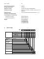
9
Order codes
HMI –
Type
Power supply
voltage
Audio
Input/output
3 DI, 3 DO
Slot for SD
4.3''
7''
7''
10''
15''
HMI 450
HMI 730
HMI 750
HMI 1050
HMI 1550
XXXX
X
X
X
0450
1
0
1
0
0
0730
0750
1
1
1050
1
1
1550
1
1
11...36V DC
1
90...250V AC
2
no
yes
X
XX
X
X
0
1
no
0
yes
1
Ethernet
no
0
yes
1
Design
standard
1)
Custom-made
Language version Polish
English
1)
other
Acceptance tests without additional requirements
with additional Quality Control certification
1)
according to the arrangements with the customer
1)
only after agreeing with the producer
0
XX
P
E
X
0
1
X
User’s manual
30
User’s manual
31
LUMEL S.A.
ul. Słubicka 1, 65-127 Zielona Góra, Poland
HMI-09
Tel.: 00386 02 608 90 10
www.materm.si
20