1
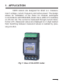
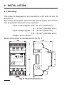
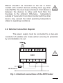
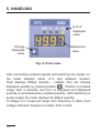
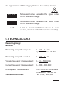
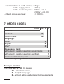
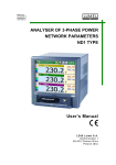
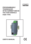
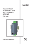
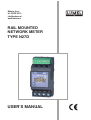
Materm d.o.o. tel: 02 608 90 10 [email protected] www.materm.si RAIL MOUNTED NETWORK METER TYPE N27D USER’S MANUAL 1 Contents 1. Application................................................................................... 5 2. meter set...................................................................................... 6 3. BASIC REQUIREMENTS, OPERATIONAL SAFETy...................... 6 4. installation............................................................................... 10 4.1. Mounting............................................................................. 10 4.2. External connection diagram.............................................11 5. HANDLING...................................................................................... 12 6. TECHNICAL DATA......................................................................... 13 7. ORDER CODES.............................................................................. 16 1.ApplicAtion N27D meters are designed for direct a.c. measurement: voltage, current, frequency and active power. The design allows for installation of the meter for modular switchgear in accordance with EN 62208 (meter has a width of 3 modules) on 35 mm rail. The current is measured through current transformer (CT). Measured values are displayed on 4 -digit readout field. Switching between measured values is realized by pressing a button. Fig.1. View of the N27D meter. 5 2. METER SET The meter set includes: - N27D meter................................... 1 pc - user’s manual................................ 1 pc - warranty certificate........................ 1 pc 3. BASIC REQUIREMENTS, OPERATIONAL SAFETY Symbols located in this service manual mean: WARNING! Warning of potential, hazardous situations. Especially important, one must acquaint with this before connecting the module. The non- observance of notices marked by these sym- bols can occasion severe injuries of the personnel and the damage of the module. CAUTION! Designates a general useful note. If you observe it, handling of the meter is made easier. One must take note of this, when the meter is working inconsistently to the expectations. Possible consequences if disregarded! In the security scope, the meter fulfills the requirements of the EEC Low-Voltage Directive (EN 61010 -1 issued by CENELEC). Remarks concerning the operator safety: 1. General • • • • The N27D meter is designed to be installed in measuring systems. Non-authorized removal of the required housing, inappropriate use, incorrect installation or operation creates the risk of injury to personnel or damage to equipment. For more detailed information please study the user’s manual. All operations concerning transport, installation, and commissioning as well as maintenance must be carried out by qualified, skilled personnel and national regulations for the prevention of accidents must be observed. According to this basic safety information, qualified, skilled personnel are persons who are familiar with the installation, assembly, commissioning, and operation of the product and who have qualifications necessary for their occupation. 2. Transport, storage • Please observe the notes on transport, storage and appropriate handling. • Observe the climatic conditions given in Technical Data. 3. Installation • The meter must be installed according to the regulation and instructions given in this User’s Manual. • Ensure proper handling and avoid mechanical stress. • Do not bend any components and do not change any insulation distances. • • • • • • Do not touch any electronic components and contacts. Meters may contain electrostatic sensitive components, which can easily be damaged by inappropriate handling. Do not damage or destroy any electrical components since this might endanger your health! Wire cross-sections must be chosen such to assure the protection of the cable in case of a short-circuit, by means of an installation cut-off. Requirements concerning the mains supply are described in the EN 61010-1 standard. A cut-out or a circuit-breaker should be installed in the building and be easily accessible for the operator. 4. Electrical connection • Before switching the meter on, one must check the correctness of connection to the mains supply. • In case of the protection terminal connection with a separate lead, one must remember to connect it before the connection of the meter to the mains. • When working on live meters, the applicable national regulations for the prevention of accidents must be observed. • The electrical installation must be carried out according to the appropriate regulations (cable cross-sections, fuses, PE connection). Additional information can be obtained from the user’s manual. • The documentation contains information about installation in compliance with EMC (shielding, grounding, filters and cables). These notes must be observed for all CE-marked products. • The manufacturer of the measuring system or installed devices is responsible for the compliance with the required limit values demanded by the EMC and LVDlegislation. 5. Operation • Measuring systems including N27D meters must be equipped with protection devices according to the corresponding standard and regulations for prevention of accidents. • After the instrument has been disconnected from the supply voltage, live components and power connections must not be touched immediately because capacitors can be charged. The housing must be closed during operation. 6. Maintenance and service Please observe the manufacturer’s documentation. Read all product-specific safety and application notes in this user’s manual. • Before taking the meter out, ensure the power supply is off. • The removal of the meter housing during the guarantee period may cause its cancellation • The meter fulfills requirements related to electromagnetic compatibility in the industrial environment. 4. INSTALLATION 4.1. Mounting The meter is designed to be mounted on a 35 mm rail acc. to EN 60715. The meter is equipped with terminals which enable the connection of external wires with cross-sections: - input current signals: 2,5 – 16 mm2 (solid wire), 4 – 16 mm2 (stranded wire); - input voltage signals: 1,5 – 16 mm2 (solid wire), 2,5 – 16 mm2 (stranded wire); 2 - supply: up to 2,5 mm . Meter dimensions are presented on the fig. 2 10 Fig. 2. Overall dimensions Meters shouldn’t be mounted on the rail in direct contact with another devices emitting heat (eg other meter N27D). You must keep a minimum 5 mm distance between the devices to allow emit heat from the housings to the ambient. Otherwise, temperature outside of meter which is in direct contact with the other device may exceed the rated operating temperature stated in operating conditions. 4.2. External connection diagram The power supply must be connected by a two-wire conductor of suitable wire cross-section ensuring its protection by an installation cut-out. Fig. 3. Electrical connections of the N27D meter 11 5. HANDLING Unit of displayed value Change displayed value Measured value Fig. 4. Front view. After connecting external signals and switching the supply on, the meter displays name N27d and software revision. Then displays default quantity – voltage. One can change displayed quantity by pressing button . If button is pressed longer than 3 seconds, text save is displayed and displayed quantity is remembered as a default quantity. After switching on power supply the meter displays its default quantity. If voltage is in measured range then frequency is taken from voltage otherwise frequency is taken from current. 12 The appearance of following symbols on the display means: ---- Measured value exceeds the upper value of the indication range. ---- Measured value exceeds the lower value of the indication range. ErCA Loss of meter calibration values. In such a case, one must contact the service workshop. 6. TECHNICAL DATA Measuring range: INPUTS: Measuring range of voltage U: 0...0.01...1.2 Un input resistance > 3 M Measuring range of current I: 0...0.01...1.2 In Voltage frequency measurement: 0...2.0...500.0 Hz Current frequency measurement: 0...45.0...500.0 Hz Active power measurement: Sustained overload: -45.4 ...-31.5...31.50...45.36 kW at frequency 45...65 Hz 120 % Un, 120 % In 13 Short duration overload (1 s): input voltage 2 Un (<1000 V) current input: 10 In Basic error: - voltage ± (0.5% of the range) in frequency range 40...500 Hz - current ± (0.5% of the range) in frequency range 45...65 Hz - frequency - active power ± (0.02% of the range) ± (1% of the range) in frequency range 45...65 Hz Additional errors in rated operating conditions: - from ambient temperature changes (50% of basic error/10 K) Preheating time: 15 minuts Measuring time: 0.5 s Rated operating conditions: - supply voltage: - input voltage Un: - input current In: - ambient temperature: - storage temperature: - humidity: - work position: - input signal: 230 V ± 10% a.c. (45...65 Hz) 500 V a.c. 0...2...40.0...500.0 Hz 63 A a.c. 0...45.0...500.0 Hz -10...23...55°C -25...+85°C < 95% (condensation inadmissible) any sinusoidal (THD 8%) 14 - admissible peak factor 2 Readout field: - display - digit height - color - indication range: 4-digit LED 8.5 mm yellow -1999...9999 Ensured protection grade: IP 00 acc. to EN 60529 Overall dimensions: 110 x 53 x 60 mm Weight: < 0.25 kg Power: - in supply input - in voltage input - in current input < 2 VA < 0.2 VA < 2.5 VA Test voltage: - voltage input 3.2 kV d.c. - current input 3.2 kV d.c. - power supply 2,1 kV d.c. Electromagnetic compatibility: - noise immunity acc. to EN 61000-6-2 - noise emission acc. to EN 61000-6-4 Safety requirements acc. to EN 61010-1: - isolation between circuits: basic, - installation category III up to 300 V (II for 300 … 600 V), - pollution grade 2, 15 - maximal phase-to-earth working voltage: - for the supply circuit 300 V, - for the measuring input 600 V – cat. II (300 V – cat. III) - altitude above sea level: < 2000 m. 7. ORDER CODES n27D- XX Version: standard 00 custom-made* XX Language: Polish English other* Acceptance tests: without extra quality inspection requirements with an extra quality inspection certificate acc. to customer’s request* * only after agreeing with the manufacturer X X P E X 0 1 X Example of order: The code: N27D - 00 E 0 means: 00 – standard version, E – English language, 0 – without extra quality inspection requirements. 16 17 18 19 LUMEL S.A. ul. Słubicka 1, 65-127 Zielona Góra, Poland Export Department: Tel.: (48-68) 45 75 139/305/321/368 Fax: (48-68) 32 54 091 e-mail: [email protected] 20 N27D-09A Tel.: (48-68) 45 75 100 Fax: (48-68) 45 75 508 e-mail:[email protected] http://www.lumel.com.pl