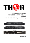
1
CBS-IP-IRD-S2-LCD User’s Manual CBS-IP-IRD-S2-LCD User’s Manual DIRECTORY Chapter 1 Product Outline ............................................................................ 1 1.1 Outline .................................................................................................................... 1 1.2 Features.................................................................................................................. 2 1.3 Specifications ......................................................................................................... 2 1.4 Principle Chart ........................................................................................................ 4 1.5 Appearance and description................................................................................... 4 Chapter 2 Installation Guide ......................................................................... 6 2.1 Acquisition Check ................................................................................................... 6 2.2 Installation Preparation........................................................................................... 6 2.3 Wire’s Connection .................................................................................................. 8 2.4 Signal Cable Connection ........................................................................................ 9 Chapter 3 Operation .................................................................................... 14 3.1 Main Interface ....................................................................................................... 14 3.2 General Setting..................................................................................................... 15 Chapter 4 NMS Setting ................................................................................ 26 4.1 Installation ............................................................................................................ 26 4.2 Software Operation .............................................................................................. 26 4.3 CBS-IP-IRD-S2-LCD NMS Operation .................................................................. 32 4.4 Other Settings....................................................................................................... 54 Chapter 5 Troubleshooting ......................................................................... 58 Chapter 6 Packing List ................................................................................ 59 Chapter 1 Product Outline 1.1 Outline This CBS-IP-IRD-S2-LCD is our new design IRD with video monitor LCD equipped on the front panel. It can receive TS signals from tuner (DVB-S/S2, DVB-T, ISDB-T, and DVB-C optional), ASI and IP sources. After multiplexing and de-encryption with CAM module, then give it to ASI, IP (MPTS and SPTS) as well as various interface video/audio output. With the CAM slot support, it can support one channel (Tuner, ASI or IP) de-scrambling and give transparent signal output. User can operate the device by using front panel LCD or NMS software. Moreover, user can choose to have an optional ASI output interface which can pass through the encryption data source directly from tuner. 1.2 Features Support DVB-C/DVB-S/ DVB-S2/DVB-T/ ISDB-T RF Input Support 1 RF, 1 ASI, and 1 IP (100M) input Support 2 channels ASI output and MPTS/32 SPTS IP output Support tuner pass through to ASI output Multiple Video and Audio format output Support H.264 and MPEG2 decoding LCD display on the front panel Unicast and multicast support Support NMS over SNMP 2 1.3 Specifications Input Multiplexing DVB-CI Parameters 1 RF input(DVB-C/DVB-S/ DVB-S2/ DVB-T/ISDB-T optional 1 ASI input(support 188/204 package format 1 IP input (100Mbps) Support 256 PID mapping per channel(automatically or manually) PCR accurate adjusting Generate PSI/SI table automatically Descrambler DVB-CSA Smart Card interface ISO7816 Interface Card Separation PCMCIA CVBS×1 (BNC) 576i@25 fps, [email protected] fps YPbPr×1 (BNC) 1080i@ 25, 29.97, 30 fps 720p @ 50 59.94 fps SDI×1 (BNC) 1080i@25, 29.97, 30 fps; 720p @ 50 59.94 fps 576i@25 fps [email protected] fps HDMI×1 1080i@25, 29.97, 30 fps; 720p @ 50 59.94 fps Stereo unbalanced audio BNC interface Stereo balanced audio XLR interface Digital audio SPDIF Video output Audio Output 2 ASI output(after multiplexer) TS Output 2 ASI output(Tuner input pass-through) 1 IP MPTS output(100M port) 32 IP SPTS output(1000M Port) Support front panel and network management software(NMS) System English and Chinese interface conversion Ethernet software upgrade General Dimensions ( L×W×H) Approx weight Power Temperature range 482mm×455mm×44.5mm 3.2kg <20W(Max) 0~45℃ (Operation); -20℃~80℃ (Storage) 3 DVB-C 47MHZ~860MHZ, 16/32/64/128/256 QAM 950MHZ~2150MHZ Symbol Rate: 2~45Mbauds DVB-S DVB-T 146MHZ~862MHZ Bandwidth: 6/7/8 M DVB-S2 950MHZ~2150MHZ Symbol Rate: QPSK 1~45Mbauds 8PSK 1-30Mbauds ISDB-T 153MHZ~862MHZ Bandwidth: 6/7/8 M RF Input Demodulation Range 1.4 Principle Chart 1.5 Appearance and description Front Panel Illustration: Indicators area: All the indicators will light on when the CBS-IP-IRD-S2-LCD works at its current mode. 1 LCD Display 2 Indicators Area 4 3 Up/Down/Left/Right Buttons 4 Enter Key 5 Menu Key 6 Lock Key 7 LCD Monitor 8 Switch Button 9 PCMCIA interface Rear Panel Illustration 1 Loop Out Interface 2 RF IN Interface 3 IP IN/OUT Interface 4 ASI IN Interface 5 ASI Out1 and ASI Out2 Interface: Output multiplexed or separated TS Stream from tuner, ASI and IP. 6 ASI Out3 and ASI Out4 Interface: Output Single TS Stream from tuner. 7 HDSDI-OUT Interface: HD/SD digital parallel output interface 8 USB interface: Software updating. 9 HDMI Output Interface 10 SPDIF: Digital audio output interface 11 CVBS: Composite video and audio output interface 12 Audio (L/R channel) output interface YPbPr: Audio and Video component output interface 13 NMS Ethernet Port(10-100Mbps) 14 Balance audio output interface 15 Integrated power switch and socket 16 Grounding Wire 5 Chapter 2 Installation Guide 2.1 Acquisition Check When user opens the package of the device, it is necessary to check items according to packing list. Normally it should include the following items: CBS-IP-IRD-S2-LCD 1pcs User’s Manual 1pcs ASI Cable 1pcs Power Cord 1pcs If any item is missing or mismatching with the list above, please contact our company. 2.2 Installation Preparation When users install device, please follow the below steps. The details of installation will be described at the rest part of this chapter. Users can also refer rear panel chart during the installation. The main content of this chapter including: Checking the possible device missing or damage during the transportation Preparing relevant environment for installation Installing modulator Connecting signal cables Connecting communication port (if it is necessary) 2.2.1 Device's Installation Flow Chart Illustrated as following: 6 Acquisition Check Fixing Device Connecting Grouding Wire and Power Cord Connecting Signal Wire Setting Parameter Running Device 2.2.2 Environment Requirement Item Requirement Machine Hall Space When user installs machine frame array in one machine hall, the distance between 2 rows of machine frames should be 1.2~1.5m and the distance against wall should be no less than 0.8m. Electric Isolation, Dust Free Machine Hall Floor Volume resistivity of ground anti-static material: 1X10⁷~1X10¹⁰,Grounding current limiting resistance: 1M (Floor bearing should be greater than 450Kg/㎡) Environment Temperature 5~40℃(sustainable ),0~45℃(short time), Relative Humidity 20%~80% sustainable 10%~90% short time Pressure 86~105KPa Door & Window Installing rubber strip for sealing door-gaps and dual level glasses for window Wall It can be covered with wallpaper, or brightness less paint. Fire Protection Fire alarm system and extinguisher Power Requiring device power, air-conditioning power and lighting power are independent to each other. Device power requires AC power 100-240V 50-60Hz. Please carefully check before running. installing air-conditioning is recommended 2.2.3 Grounding Requirement All function modules’ good grounding is the basis of reliability and stability of devices. Also, they are the most important guarantee of lightning arresting and interference rejection. Therefore, the system must 7 follow this rule. Coaxial cables outer conductor and isolation layer should keep proper electric conducting with the metal housing of device. Grounding conductor must adopt copper conductor in order to reduce high frequency impedance, and the grounding wire must be as thick and short as possible. Users should make sure the 2 ends of grounding wire well electric conducted and be antirust. It is prohibited to use any other device as part of grounding electric circuit The area of the conduction between grounding wire and device’s frame should be no less than 25mm2. 2.2.4 Frame Grounding All the machine frames should be connected with protective copper strip. The grounding wire should be as short as possible and avoid circling. The area of the conduction between grounding wire and grounding strip should be no less than 25mm2. 2.2.5 Device Grounding Connecting the device’s grounding rod to frame’s grounding pole with copper wire. 2.3 Wire’s Connection The grounding wire conductive screw is located at the right end of rear panel, and the power switch, fuse, power supply socket is just beside ,whose order goes like this, power switch is on the left ,power supply socket is on the right and the fuse is just between them. 8 Connecting Power Cord User can insert one end into power supply socket, while insert the other end to AC power. Connecting Grounding Wire When the device solely connects to protective ground, it should adopt independent way, say, share the same ground with other devices. When the device adopts united way, the grounding resistance should be smaller than 1Ω. Caution: Before connecting power cord to CBS-IP-IRD-S2-LCD, user should set the power switch to “OFF”. 2.4 Signal Cable Connection The signal connections include the connection of input signal cable and the connection of output signal cable. The details are as follows: 2.4.1 CBS-IP-IRD-S2-LCD Cables Illustration: IP Input Cable Illustration: HDMI Cable Illustration 9 XLR Interface Cable Illustration: RF In and Loop Out Cable Illustration: Component Output, CVBS Output and Sound Channel Output Cable Illustration: ASI Input and Output Cable Illustration: 10 2.4.2 CBS-IP-IRD-S2-LCD Satellite Receiver Signal Cable Connection Illustration: RF IN and LOOP OUT Connection Illustration: Users can find the RF IN and LOOP OUT interface on the device according to the connector mark described on the rear panel illustration, and then connect the cable. One end is connected to the RF IN interface of satellite receiver while the other end is connected to the satellite signal source equipment or LOOP OUT interface of the previous satellite receiver when several satellite receivers are series connection. As follows: ASI IN and ASI OUT Connection Illustration: Users can find the ASI IN and ASI OUT interface on the device according to the connector mark described on the rear panel illustration, and then connect the cable. One end is connected to ASI IN interface of the CBS-IP-IRD-S2-LCD, the other end is connected to any device that has ASI output, while when connected ASI OUT interface, the other end of the wire is generally connected to encoder and multiplexer. As follows: 11 Component Output, CVBS Output and Sound Channel Output Connection Illustration: Users can find the YPbPr, CVBS and Left/Right sound channel interface on the device according to the connector mark described on the rear panel illustration, and then connect the cable. The other end of the wire is connected to encoders. HDMI Output Connection Illustration: Users can find the HDMI interface on the device according to the connector mark described on the rear panel illustration, and then connect the wire. One end of the wire is connected to the HDMI output interface of the CBS-IP-IRD-S2-LCD, while the other end of the wire is connected to encoder or other equipment. As follows: IP Output Connection Illustration: Users can find the IP OUTPUT interface on the device according to the connector mark described on the rear panel illustration, and then connect the wire. One end of the wire is connected to the IP output interface of the CBS-IP-IRD-S2-LCD, the other end of the wire is connected to devices 12 with IP INPUT. As follows: XLR Output Connection Illustration: Users can find the XLR interface on the device according to the connector mark described on the rear panel illustration, and then connect the wire. One end of the wire is connected to the XLR output interface of the CBS-IP-IRDS2-LCD, the other end of the wire is connected to IP encoder. As follows: 13 Chapter 3 Operation The front panel of CBS-IP-IRD-S2-LCD is the user-operating interface and the equipment can be conveniently operated and used by user according to the procedures displayed on the LCD; the simple using method for the machine is as follows: Keyboard Function Description: MENU: Cancel current entered value, resume previous setting; Return to previous menu. ENTER: Activate the parameters which need modifications, or confirm the change after modification. LEFT/RIGHT: Choose and set the parameters. UP/DOWN: Modify activated parameter or paging up/down when parameter is inactivated. LOCK: Lock the screen/cancel the lock state. After pressing the lock key, the LCD will display the current configuring state. 3.1 Main Interface After switching on the IRD and pressing the “LOCK” key on the front panel to enter to the main menu, the LCD will display the following pages: 1. Input Setting 2. Output Setting 3. Decoder Setting 4. Descramble Set 5. Network Setting 6. Saving Config 7. Loading Config 8. Version 14 3.2 General Setting User could do all the settings according to the 8 directions displayed on the LCD. 3.2.1 Input Setting User can press “Enter” key to enter into the menu of the input setting. 1.1 Tuner (DVB-S2) 1.2 ASI 1.3 IP 3.2.1.1 Tuner In Here we take 1.1 Tuner (DVB-S2) signal in as an example: The page menu from 1.1 to 1.3 represents the tuner, ASI and IP input ports of the IRD. User can multiplex the input programs from any port to output any program or all the programs at the same time. By pressing the “Enter” key, the device will take a while to analyze the input TS or signal and then display the program list at the submenu, say, 1.1.1-1.1.6 1.1.1 Prog Parse 1.1.2 Sat freq Set 1.1.3 LNB freq Set 1.1.4 Symbol rate 1.1.5 LNB Voltage 1.1.6 22KHZ Switch By pressing the “Enter” key to enter the submenu of 1.1.1 1.1.1 Prog Parse Prog:00 Mux:00 At the submenu 1.1.1, It displays the quantity of total parsed programs and 15 and multiplexed programs. User also could check and set the Satellite frequency, LNB frequency, Symbol rate and LNB voltage in its corresponding submenu “1.1.2”, “1.1.3”, “1.1.4”, “1.1.5”. 1.1.2 Sat freq Set 3150MHZ 1.1.3 LNB freq Set 5150MHZ 1.1.4 Symbol rate 17500KHZ 1.1.5 LNB Voltage Horizonta(18v) At the submenu 1.1.6, user can decide whether to turn on/off the 22 KHZ Switch. 1.1.6 22KHZ Switch OFF ON 3.2.1.2 ASI IN By pressing the “Enter” key, users can enter the submenu of 1.2.1. 1.2.1 Prog Parse Prog:00 Mux:00 3.2.1.3 IP IN By pressing the “Enter” key, it displays below page: 1.3.1 Prog Parse 1.3.2 Input Ip Addr 1.3.3 Input Port 16 By pressing the “Enter” key to enter the submenu of 1.3.1, 1.3.2 and 1.3.3 respectively, it will display below pages: 1.3.1 Prog Parse Prog:00 Mux:00 1.3.2 Input Ip Addr 224.002.002.002 1.3.3 Input Port 1234 3.2.2 Output Setting User can press “Enter” key to enter into below menu of the output setting. 2.1 Multiplex Set 2.2 Output Bitrate 2.3 Transtream ID 2.4 Original NetID 2.5 IP Output 3.2.2.1 Multiplex Set User can enter to the menu 2.1 and select the way of outputting signals. By pressing UP/DOWN key after pressing Enter key, user can see the four ways of outputting the Signals in turn: ASI, IP, Tuner pass through and Mux. 2.1 Multiplex Set Tuner Passthrough 2.1 Multiplex Set ASI 2.1 Multiplex Set IP 2.1 Multiplex Set Mux 17 3.2.2.2 Output Bitrate By pressing the “Enter” key, users can enter the menu of 2.2. 2.2 Output Bitrate 060Mbps 3.2.2.3 Transtream ID By pressing the “Enter” key, users can enter the menu of 2.3. 2.3 Transtream ID 00000 3.2.2.4 Original NetID By pressing the “Enter” key, users can enter the menu of 2.4. 2.4 Original NetID 00000 3.2.2.5 IP Output By pressing the “Enter” key, users can enter the menu of 2.5. It will display below pages, user can set the output IP address, output port and decide whether ouput the signals from IP port. 2.5.1 IP Out Enable 2.5.2 Out IP Addr 2.5.3 Out Port 2.5.1 IP Out Enable ON OFF 2.5.2 Out IP Addr 224.002.002.002 2.5.3 Out Port 1001 3.2.3 Decoder Setting 18 User can press “Enter” key to enter into below menu of the decoder setting and execute video setting, audio setting, program selecting, search and decoder selecting. 3.1 Video Setting 3.2 Audio Setting 3.3 Program Select 3.4 Search 3.5 Decoder Select 3.2.3.1 Video Setting After pressing enter key, user can enter the submenus: 3.1.1, 3.1.2, 3.1.3, 3.1.4, 3.1.5, 3.1.6. 3.1.1 Resolution Auto By pressing UP/DOWN after entering above menu, user can see all the options of resolution: 1080I@50, 1080I@60, 720P, 576P, 576I, 480I, 480P, [email protected], [email protected]. 3.1.2 Standard PALBDGHI By pressing UP/DOWN after entering above menu, user can see all the options of standard. 3.1.3 Subtitle OFF ON 3.1.4 CC Switch OFF ELA608 ELA708 3.1.5 Finger Switch OFF 3.1.6 Aspect Ratio 16:9 FULL 19 3.2.3.2 Audio Setting User can enter into below submenu by pressing the “Enter” key. Then select the audio, choose the ES mode (consists of stereo, left channel and right channel), adjust the volume, select mode of Audio SPDIF and Audio channel. 3.2.1 Audio Select 3.2.2 ES Mode 3.2.3 Volume 3.2.4 Audio SPDIF 3.2.5 Audio Channel 3.2.1 Audio Select eng 3.2.2 ES Mode Stereo 3.2.3 Volume 12 3.2.4 Audio SPDIF Auto 3.2.5 Audio Channel Auto 3.2.3.3 Program Select Before entering this menu to select the programs, user should enter the menu 3.5 and 3.4 in turn to find the programs. 3.3 Program Select 1 CCTV-1 By prssing UP/DOWN after above menu, all the searched programs will be 20 displayed individually as below: 3.3 Program Select 2 CCTV-2 3.2.3.4 Search The device will start searching the programs automatically after user select the mode of decoding in the menu 3.5. 3.4 Search Start Searching 3.2.3.5 Decoder Select There are three ways of decoding: Tuner, ASI and IP. User can press UP/DOWN to see the way individually after entering below menu. 3.5 Decoder Select 1 Tuner 3.2.4 Descramble Setting User can press “Enter” key to enter into below menu of the descramble setting. The detailed operation about the descramble function will be explained on the NMS operation part (Chapter 4). 4.1 Card Setting 4.2 Biss Two functions of descrambling, each option works alone. 3.2.4.1 Card Setting After enter the submenu of 4.1, it will display the following page: 21 User can set the input signals here. 4.1.1 Input Select 4.1.2 A Card Info 4.1.3 B Card Info 4.1.4 Pro Select 4.1.5 CI Bitrate If users don’t insert any card, after entering the menu 4.1.2 and 4.1.3, it will show “Empty” to indicate there is no card information. 3.2.4.2 BISS BISS is one of the descrambling functions which support two modes: mode 1 and mode E. And the application needs to be matched with BISS scrambler. User can select the mode based on the kind of BISS scrambler. 4.2.1 Select Mode 4.2.2 Mode 1 4.2.3 Mode E 3.2.5 Network Setting User can press “Enter” key to enter into below menu of the network setting. 5.1 IP Address 5.2 Subnet Mask 5.3 Gateway 5.4 MAC Address 5.5 Service IP 5.6 SPTS Net Config 3.2.5.1 IP Address After entering 5.1, it will display the following page: 5.1 IP Address 192.168.002.136 3.2.5.2 Subnet Mask After entering 5.2, it will display the following page: 22 5.2 Subnet Mask 255.255.255.000 3.2.5.3 Gateway After entering 5.3, it will display the following page: 5.3 Gateway 192.168.002.001 3.2.5.4 MAC Address After entering 5.4, it will display the following page: 5.4 MAC Address 201205071337 3.2.5.5 Service IP After entering 5.5, it will display the following page: 5.5 Service IP 192.168.003.137 3.2.5.6 SPTS Net Config After entering 5.6, it will display the following page: 5.6.1 SPTS Config 5.6.2 SPTS IP Addr 5.6.3 SPTS Gateway 5.6.4 SPTS Enable 5.6.5 SPTS Para Prog 3.2.5.6.1 SPTS Config After entering 5.6.1, it will display the following page: 5.6 Output Disable Digital 1 By pressing UP/DOWN button after entering this interface, user can see 32 programs in turn. 23 User can select ON/OFF to output Enable Select ON OFF the program through GE port. Device supports multicast under this 5.6.1 IP Addr Set 224.002.002.002 IP Address and unicast under the IP Address 192.168.xxx.xxx 5.6.2 IP Port Set 1001 3.2.5.6.2 SPTS IP Address After entering 5.6.2, it will display the following page: 5.6.2 SPTS IP Addr 192.168.012.138 3.2.5.6.3 SPTS Gateway After entering 5.6.3, it will display the following page: 5.6.3 SPTS Gateway 192.168.012.075 3.2.5.6.4 SPTS Enable After entering 5.6.4, it will display the following page: 5.6.4 SPTS Enable ON OFF User can turn ON/OFF button to enable or disable the SPTS output function. 3.2.5.6.5 SPTS Para Prg After entering 5.6.5 it will display the following page: By pressing “Enter” key, users can parse 5.6.5 SPTS Para Prg Analysis Finish ## the programs to be outputted through GE port. 3.2.6 Saving Config User can choose “Yes” or “No” to save the current configuration parameters 24 at this menu. 6 Saving Config? Yes No 3.2.7 Loading Config User can restore the device into the last saved configuration by choosing the menu 7.1”Saved Config”, and also user can restore the device into factory default configuration by choosing the menu 7.2”Default Config”. 7.1 Saved Config 7.2 Default Config 7.1 Saved Config ? Yes No 7.2 Default Config ? Yes No 3.2.8 Version User can check the device’s hardware version and software version at this submenu: SW 3.05 Electronic HW 1.00 25 Chapter 4 NMS Setting Network Management System Profile Network management system is applied to digital TV equipment operation, control, management and parameters setting, etc. It centralizes digital TV equipment through network. 4.1 Installation The software doesn’t need special installation. User can just copy “Network Management Software X.XXY.exe” to the specified directory (X.XX is version number, Y represents language. For example: the version number of network management software 4.01E.exe is 4.01 English version) or place different versions of network management software to the same directory. When the network management software is running, it will generate two documents as follows: Network management software X.XXY.log (It preserves the log file.) Info. Bin (It’s the user configuration data.) 4.2 Software Operation 4.2.1 Login Interface A login interface will pop up firstly when the software is running and give user prompts to input user name and password (The default user name is admin and no password. User can add users and passwords as needed. Details please refer to 4.4.3 in 4.4 Other Settings.). The menu shows as follows: 26 User can login the NMS by pressing OK key after inputting user name. Upon the inputs, the software will verify them with database record automatically and the main interface will appear. 4.2.2 Main Interface User can create a device node tree in the left column by adding, modifying and deleting the device node. This software provides a powerful node 27 operation function, and the user can edit various parameters in the device tree for management and classification. 4.2.3 Adding Frequency Point The Add Freq Point dialog box popes up when the user clicks the Add Main Freq Point item in the Edit pull down menu on the menu row. User can also click right mouse key to pop up the short-cut menu in device tree or in the left blank column, then the Add Freq Point dialog box popes up by choosing Add Main Freq Point. The device will confirm the given frequency while user clicks OK. 4.2.4 Adding Equipment under Given Frequency Point User should choose the frequency point in advance, and then the dialog box of Add Equipment will pop up when user clicks Add Equipment item in the 28 Edit pull-down menu on the menu row or clicks right mouse key to pop up the short-cut menu in device tree or in the left blank column, then the Add Equipment dialog box will pops up after user choose Add Equipment. 4.2.5 Edit Equipment Interface User should follow the steps as below: Input the device IP Address Input the device Port Number Input the Equipment Name Choose the connected equipment type in drop down list of “Equipment Type” by clicking the “▼” or click “?” button to auto search. 29 The device will confirm the equipment when user clicks OK, and the light turns green if it links the equipment successfully. NOTE: The default IP address of CBS-IP-IRD-S2-LCD is 192.168.2.136, you can also check it in the front panel of device in case the IP changed unexpected. The PC IP address and device IP address should be in the same network. For example the Device IP is 192.168.2.1. Submask is 255.255.255.0. So the PC IP address should be 192.168.2.X (1<X<255), submask is 255.255.255.0. 4.2.6 Delete Equipment User can select the equipment to be deleted in the left column, then click the “delete” item in the pull down menu which appears by clicking the right mouse key. 30 4.2.7 Save Configuration After finishing all the parameters setting, user can click button on the toolbar to save the modifications permanently to the device’s flash. When running the network management system next time, user can reload the saved parameters from device’s flash and refresh the device’s parameters setting according to the loaded values by clicking and there is no need to reset the parameters once again, which is a very effective way for user to operate this system. Alternatively, user can also click the button on the toolbar to popup the “save file” dialog box, which gives prompts to save all the device’s parameters as binary files in the computer’s hard disk. Similarly, user can choose to click the button on the toolbar to popup the read file dialog box, to read the stored binary file and set the device’s parameters according to the loaded binary files. 31 4.3 CBS-IP-IRD-S2-LCD NMS Operation 4.3.1 Input Setting Before executing the input setting, user should select the output mode firstly. After selecting the output mode, user should click current parameters. Then click to to make the save the parameters permanently to the device’s flash. According to the output mode, user can decide which signals will be inputted and then do the input setting. There are four output modes: Mux, Tuner Passthrough, ASI Passthrough, IP Passthrough. Mux: multiplexing all the signals from IP, ASI and Tuner sources. Tuner passthrough: only signals from tuner source. ASI passthrough: only signals from ASI source. IP Passthrough: only signals from IP source. Get: reading the current device’s activating parameters and show them on 32 NMS software. Set: making the current parameters, which show in the NMS software, activate. Search: searching the program based on the current parameters. Let’s take output mode as “Mux” for example, user need to set the ASI, IP and Tuner inputs. The detailed operations will be found in 4.3.1.1, 4.3.1.2 and 4.3.1.4. 4.3.1.1 Tuner (DVB-S/S2) Setting After entering below interface, user can set the tuner parameters. User can click to read the current device’s activating parameters. Then click to make the current parameters. 4.3.1.1.1 Downlink Frequency The downlink frequency is decided by satellite. Users can search the satellite frequency on website. Normally the satellite frequency is fixed. If there is any change about it, there will be notifications on the website. 4.3.1.1.2 Symbol Rate The DVB-S/-S2 symbol rate ranges from 1Msymbol/s to 45 Msymbol/s. 4.3.1.1.3 Polarization 33 The Polarization can be vertical (13V) and horizontal (18V) 4.3.1.1.4 22 KHz By switching “ON” and “OFF” on the pull-down list, users can switch the satellite which provides signal input. 4.3.1.1.5 LNB Frequency Users have four LNB frequency choices: 5150MHz, 9750 MHz, 10600 MHz and 11300 MHz. Users should select one of them to input. Before inputting, users should select one LNB frequency from the four choices and minus the satellite frequency. If the result does not locate in range 950MHz~2150MHz, then users should select another one to make calculation. If the result locates in range 950MHz~2150MHz, then the selected LNB frequency is the right choice selected and it can be input here. 4.3.1.2 IP Setting After entering below interface, user can set the Input IP Address and Port. The Input IP Address and Input port should be matched with the IP source device. Once done, please click then click to make the current parameters and to save the parameters permanently to the device’s flash. 34 4.3.1.3 ASI Setting User can do the ASI setting simply by connecting the ASI cable to the device. There is no other setting in the NMS part. 4.3.2 Mux If all the TS are free to air, after finishing the input setting, user can enter the “Mux” part to multiplex and output the programs, otherwise, user needs to descramble the TS firstly. 35 The input program information in the left column represents all input programs and where they are come from, while the output program information in the right column represents the output programs and where they are come from. User can parse the programs of each signal source and multiplex those programs to the output. Moreover, user can modify the output programs’ Program Name, PMT, PCR, video, audio PID. 4.3.2.1 Timeout User can set the input refresh time in this blank. 4.3.2.2 Refresh input Initially, system would not show any programs at any port. Tuner, ASI and IP are the three signal sources. All the input programs can be parsed from Tuner, ASI and IP respectively and displayed on the left frame. For example, if user wants to parse the program information from tuner, he/she can choose the tuner firstly, and then click to parse the program. About few seconds later, the programs’ information will be displayed in the left frame. Sometimes, it will take a long time to parse the programs, if the programs of input TS are very complicated. The “time-out” fields decide what time the device will give up parsing programs if the analyzing process hasn’t finished yet. The methods of parsing programs from ASI and IP are the same. 36 37 4.3.2.3 Refresh output User can get the output program list and from which they come. 4.3.2.4 Select Program User can select the program from input port and click button to send it to output. The methods of operation are as following: First, pitch on the programs which need to be multiplexed by clicking the programs in the left column. Second, Click button. And then the selected program will be multiplexed to the output TS. 38 4.3.2.5 Cancel Program User can delete the selected program from output TS by clicking . 4.3.2.6 Modify Program User can trigger a window to modify the program’s properties and attributes. In case user intends to customize the details of the programs, user can select the target program and click Modify Program button between the 2 frames, then the modify interface pops out as shown above. User can select the item to be modified and input new information in the corresponding box below. To prosper the modification, please click the Set botton right corner, and then Modify botton at at left corner. The modified programs are displayed in the right box and an illustration for reference is as follows: 39 After modifying, user can see the program name has been updated in the target program as below: 40 4.3.3 Descramble Setting There are two functions of descrambling: Card and Biss. Each function works alone. User can decide to choose which function to descramble the programs based on the former source’s scrambling type. Before executing the descramble functions, user should select the signal source first. Then click to make the current parameters. The signal source may be tuner, ASI and IP. Usually, the signal comes from tuner source are scrambled. Here, let’s take it for example. If there is no card inserting into the PCMCIA interface, it will show “empty” in this blank. 41 4.3.3.1 Card After user inserting the card into the PCMCIA interface and enter below interface, please click to read the current device’s activating parameters. All the programs will be displayed in this interface as below: After clicking button, user can enter to below interface to select the card. From above box, user can see they are three choices of card selecting: Unselected, CARD A and CARD B. If users select “No-selected” button, it means users do not select any card for descrambling 42 If users select “CARD-A” button, the device will descramble programs through card A If users select “CARD-B” button, the device will descramble programs through card B Let’s select Card-A for illustration. After clicking button, Card-A will displayed in below interface. 4.3.3.2 Biss The BISS descrambling function application needs to be matched with BISS scrambler. The BISS window is showed as follows: The CBS-IP-IRD-S2-LCD BISS descrambling support two modes: “Mode 1” 43 and “Mode E”. Users can select one of the two modes in the drop down list, which shows as below: 4.3.3.2.1 Mode 1 Under Mode 1, the BISS scrambler applies scrambling by a fixed Control Word (CW), derived from a clear SW (Session Word). In Mode 1, a fixed 12character SW is inserted in the scrambler. The 64-bit CW is derived from the SW according to DVB-CSA specification. Users can select Mode 1 in the drop-down menu, and then input the descrambler key. The descrambler key consists of 12 characters from 0, 1, 2, 3, 4, 5, 6, 7, 8, 9, A, B, C, D, E, and F. The IRD descrambler key equals SW Data on the BISS scrambler side. After input the descrambler key, users should press “Set” to initial descrambling. A few seconds later, the programs will be descrambled. 4.3.3.2.2 Mode E Under Mode E, the BISS scrambler completes scrambling through ESW value and ID Select. The ESW value equals Descrambler key on the IRD side, while the ID Select equals Burned Key on IRD side. The BISS scrambler ID Select has two options: Device and Input. If Users choose Device, the Burned Key needs to be selected when descrambling, while if users choose Input and set Input data, on IRD side, users do not need to select Burned Key and input the Input data as SK. Under Mode E, users can select Burned Key option or not. Under Mode E, the device will calculate a new date which works as descrambling key. The new data is created by Descrambling Key (refers ESW on scrambler side) and Burned Key (Input or Device mode on the scrambler side). If users select 44 Burned Key, it corresponds to the Device mode selected on scrambler side; while if Burned Key unselected, it corresponds to Input mode on scrambler side. The Input data is SK on the IRD. User can input the SK in the column as showed: 4.3.3.2.3 Mode E (Burned Key option unselected) After selecting Mode E and Burned Key unselected, users should input the 16 figures Descrambler Key and 14 characters SK (the SK data refers to the Input Data on scrambler side). Users should choose the characters from 0, 1, 2, 3, 4, 5, 6, 7, 8, 9, A, B, C, D, E, and F. Lastly users press “Set” to initial descrambling. A few seconds later, the programs will be descrambled. Note: Under this mode, after inputting the Descrambler Key and SK, it will work out a new data, which can be seen as the SW in Mode 1. The new data resulted from Descrambler Key and SK implements descrambling function. 4.3.3.2.4 Mode E (Burned Key option selected) After selecting Mode E and Burned Key, users should input the 16 figures Descrambler Key (named ESW on scrambler side). Users should choose the characters from 0, 1, 2, 3, 4, 5, 6, 7, 8, and 9, A, B, C, D, E, and F. Under this mode, SK cannot be input in the column, as the data which works with ESW has been embedded inside the device after users select Burned Key (which refers that users choose Device mode on the scrambler side). Lastly users press “Set” to initial descrambling. A few seconds later, the programs will be descrambled. Note: The Burned Key is embedded in the device and it is solely controlled by the device supplier. 45 4.3.4 Transmit The transmit part is actually the PID Pass. Under some circumstances, there are certain PIDS which don’t belong to any program, but user wants to pass them through the multiplexing module without any data missing or changing. This is the main purpose of this function. The display will show as below when user clocks “Add” button. The source channel of PIDs to be bypassed The value of PID source The value of output PID which has been bypassed In this interface, user can input and check the source of PIDs in the first box, the value of PIDs source in the second box and value of outputting PIDs which has been bypassed. Clicking “OK”, user can return to the interface 46 shown as below and proceed to other operations through buttons listed beside. 4.3.5 MPTS Output Setting The device can output MPTS through FE port in the rear panel. User just needs to set the output IP address and port in below interface. Attention: The output IP can be enabled by selecting the √. 4.3.6 SPTS Output Setting The device can output SPTS through GE port in the rear panel. User can enter below interface to prosper the SPTS output setting. 47 The ways are as following: First, click to parse the programs to make it show in the blank frame. The interface will show below: CBS-IP-IRD-S2LCD supports 32xSPTS IP output. Hence, user can parse 32 programs here. Second, enable SPTS output function by clicking √ in the interface and click 48 Third, click and change enable status for each program in the pop up dialogue by selecting ON/OFF, Then click IP address can be changed to 192.168.xxx.xxx to unicast the programs. As CBS-IP-IRD-S2-LCD supports both unicast and multicast, it will multicast the programs under the current IP Address. Finally, user can see the updated enable status in below interface. 49 4.3.7 Decoder Setting User can go on decoder selecting, program searching, program selecting, audio setting and video setting in below interface. 4.3.7.1 Decoder Select There are three choices in the decoder selecting part: Tuner, ASI and IP. User can select each source and click parameters. 50 to make the current 4.3.7.2 Search After selecting the signal source, click to search the programs. Progress bar 4.3.7.3 Program Select All the searched programs will be displayed in the pull down list beside the “program select” in below interface and click parameters. 51 to make the current 4.3.7.4 Audio Setting User can select the audio, choose the ES mode (consists of stereo, left channel, right channel), adjust the volume, select mode of Audio SPDIF and Audio channel in below interface. 4.3.7.5 Video Setting User can select the resolution, standard, aspect ratio and turn on/off the subtitle, cc switch, finger switch in below interface. 52 4.3.8 IP Modification Users can click Operate and select Modify IP in the drop down list, and a dialog box presents itself as shown below. Users input the new NMS IP Address for the device and click OK button to confirm. Users can note the indicator light turns red, which signifies the equipment is 53 disconnected. Users can click right mouse key to pop up the short-cut menu in device tree by inputting the new IP to re-connect the equipment. Users can refer to the indicator light to see the connection state. If it is green, then the device is successfully connected. 4.4 Other Settings 4.4.1 Difference between Set and Remote Save In many cases during the configuration of parameters in NMS, users save the modified configuration by clicking “Set”, in which way the configuration can 54 only be saved temporarily and will restore the last saved configuration if the device reboots. To save the configuration permanently, it is required to operate through “Remote Save” on the toolbar explained in 4.2.7. This is the difference between “Set” and “Remote Save”. 4.4.2 IP Modification Users can click Operate and select Modify IP in the drop down list, and a dialog box presents itself as shown below. Users input the new NMS IP Address for the device and click Modify button to confirm. 55 Users can note the indicator light turns red (see below), which signifies the equipment has disconnected. Users then can refer to below prompts to edit the property by inputting the new IP to re-connect the equipment. After finishing all the parameters setting, user should click button on the toolbar to save the modifications to the device’s flash. 4.4.3 User Add When logging in, user will note that the default user name is admin and no password. User can add users and passwords as needed. 56 User clicking “Setting” in the menu bar and selecting “User Setting” in the pull-down list, the below dialog box will pop out as shown below. Select the “Edit Information” by marking the check box with “√”, user can input the new username and new password as prompts below. It is required to click to add the new user and then click setting. 57 to save the new Chapter 5 Troubleshooting Our ISO9001 quality assurance system has been approved by CQC organization. For guarantee the products’ quality, reliability and stability. All products have been passed the testing and inspection before ship out factory. The testing and inspection scheme already covers all the Optical, Electronic and Mechanical criteria which have been published by us. To prevent potential hazard, please strictly follow the operation conditions. Prevention Measure Installing the device at the place in which environment temperature between 0 to 45 °C Making sure good ventilation for the heat-sink on the rear panel and other heat-sink bores if necessary Checking the input AC voltage within the power supply working range and the connection is correct before switching on device Checking the RF output level varies within tolerant range if it is necessary Checking all signal cables have been properly connected Frequently switching on/off device is prohibited; the interval between every switching on/off must greater than 10 seconds. Conditions need to unplug power cord Power cord or socket damaged. Any liquid flowed into device. Any stuff causes circuit short Device in damp environment Device was suffered from physical damage Longtime idle. After switching on and restoring to factory setting, device still cannot work properly. Maintenance needed 58 Chapter 6 Packing List CBS-IP-IRD-S2-LCD 1 piece User’s Manual 1 piece Power Plug for AC Input 1 piece ASI Wire 1 piece 59