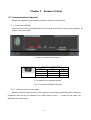
1
Intepro Systems PAS-F Series User Manual ©2015 All rights reserved by Intepro Systems Version 1 Version History Version No. V1.0 Release date 4-2015 Writer Description Rev 1 Hardware version applied Intepro Systems provides a full range of technical support for our customers. Customers can contact our offices or customer service centers nearby, or our headquarters. All rights reserved. This manual is subject to change without notice. Safety Precautions Danger Beware o f the high temperature of this equipment. DO NOT open the chassis without technician present or authorization from Intepro Systems. • When the PAS-F needs to be moved or rewired, please shut down the instrument completely by disconnecting the input power lines and wait at least 20 minutes for the capacitors in the instrument to discharge to prevent electric shock. • In order to ensure the personal safety of users, this series of power products must be grounded before use. • In case of fire, please use dry powder fire extinguishers instead of liquid fire extinguishers to avoid the risk of electric shock. • Liquid or other foreign objects must not be allowed to enter the cabinet of the grid simulator. Attention The application environment and storage methods affect the service life and reliability of the product. Extended use in the following conditions should be avoided: • Ambient high or low temperatures or humidity beyond technical specifications (temperature: -20℃to 40℃; relative humidity: 5% to 95%); • In direct sunlight or exposed to heat sources; • Places susceptible to vibration or collision; • Environments with dust, corrosive substances, salt and combustible gases; Keep the air inlets and outlets unblocked to promote ventilation to avoid a rise in the internal temperature, which may shorten the service life of components, and affect the service life of the product; Grid simulators not in service for a long time should be stored in a dry environment. The temperature range for storage is -40℃to 70℃. To properly protect the equipment, only the personnel of Intepro Systems are allowed to open the front door or side cover. If the quality assurance seal is broken, required services will incur charges and guaranty is void. Danger: conditions that may cause serious equipment damages or human casualties. Attention: Conditions that may cause moderate injuries or damages to equipment. Content 1 Introduction ............................................................................................................................... 1 2 Specifications............................................................................................................................ 2 2.1 Specifications Table................................................................................................ 2 3 4 2.2 Physical dimensions.......................................................................................................... 3 2.3 Illustration of outline .......................................................................................................... 4 Transportation and Installation ............................................................................................... 6 3.1 Notes on transportation:..................................................................................................... 6 3.2 Inspection after unpacking ................................................................................................. 6 3.3 Requirements of the environment ...................................................................................... 7 3.4 Instructions and illustrations on wiring ............................................................................... 9 3.5 Notes on wiring ................................................................................................................ 10 Operations................................................................................................................................ 11 4.1 First time start-up ............................................................................................................. 11 4.2 Instructions on UI software ............................................................................................... 11 4.2.1 Initializing ...................................................................................................................... 11 4.2.2 User .............................................................................................................................. 13 4.3 Applications selection ....................................................................................................... 14 4.3.1 General mode ................................................................................................................ 14 4.3.2 Step mode ......................................................................................................................15 4.3.3 Gradual mode ................................................................................................................ 17 4.3.4 Low voltage ride through (LVRT)................................................................................... 19 4.3.5 Measure ......................................................................................................................... 21 4.3.6 System set ..................................................................................................................... 22 4.3.7 Events log ...................................................................................................................... 23 5 Remote Control ........................................................................................................................ 24 5.1 Communication channels ..................................................................................................... 24 5.1.1 Connector of RS485........................................................................................................24 5.1.2 Remote Control on touch panel.......................................................................................24 5.2 Operations of remote control on PC ..................................................................................... 25 5.2.1 Software installation .......................................................................................................25 5.2.2 Operations on PC ............................................................................................................27 6 7 8 Theory of the functions of machine ....................................................................................... 41 6.1 Block diagram .................................................................................................................... 41 6.2 Illustration of the block diagram ........................................................................................ 41 6.3 Structure of the main control ............................................................................................. 42 Maintenance............................................................................................................................... 43 7.1 Routine maintenance ......................................................................................................... 43 7.2 Periodic maintenance ........................................................................................................ 44 Customer Service...................................................................................................................... 45 Warranty Card ................................................................................................................................ 46 Chapter 1 Introduction The PAS-F series (hereinafter referred to as “this machine” or “the machine”) is the newest generation of bi-directional AC source in our company. PAS-F employs the most advanced PWM rectification (active rectification) technology with four-quadrant operation capability. It is able to provide excellent sinusoidal voltage output and achieve very high output voltage and frequency stability. All necessary protection mechanisms are implemented in the electronic circuitry to quickly detect, execute proper actions immediately and activate necessary alarms. Those protections include overload, over-current, over-voltage and short-circuit protection. Laminated bus-bar technology used on the DC bus combined with high efficient IGBT modules further increase the reliability and stability of the machine. This machine can be controlled by either the touch panel installed on it (the local control) or by the communication channels (eg. RS485) connected to an external computer (the remote control). Either way of control has a user friendly interface which makes the users in controlling and programming this machine much easier than before. Main characteristics of the PAS-F: Able to absorb energy from the output terminals then convert it and feed into the grid power, help the industry to conserve energy and reduce carbon emission. Employs the most advanced PWM rectification (active rectification) technology with four-quadrant operation capability; Very high input power factor , up to 0.99; Very low input current harmonics; Pure sinusoidal output voltage, THD < 1%; Interactive and user friendly interface; Versatile communication channels and protocols supported; Diversified in machine capacity, meet requirements from all kinds of customers. 1 Chapter 2 Specifications 2.1 Specifications Table Model no. PAS-F-33060 60 KVA Output capacity(KVA) Circuit topology AC input AC output PWM rectification + SPWM inverter with IGBT modules Phase type 3-phase, 3-wire Line Voltage 380V±15% Frequency range 47-63Hz Power factor 0.99 Ithd ≤3%(Typical) Phase type 3-Phase, 4-wire Phase Voltage 0V ~ 300.0V(L-N) Frequency range 40-65Hz Maximum current 83.3A Line regulation <0.5% Load regulation ±0.5% (Linear load) Frequency stability Output Features ≤0.01% Waveform distortion (THD) Display ≤1% (Linear load) Efficiency ≥92% Response time ≤2ms Crest factor 3:1 Terminal 7”touch panel Voltage 0.2V+0.1%FS, Resolution:0.1V Current 0.2A+0.1%FS, Resolution:0.1A Frequency 0.01Hz+0.01%FS, Resolution:0.01Hz Real power 0.2kW+0.1%F, Resolution:0.1kW Apparent power 0.2kVA+0.1%FS, Resolution:0.1kVA Power factor ±0.01, Resolution:0.01 Communications RS485 (for standard machine) Insulation resistance Safety Dielectric Withstand Voltage 10MΩ (test voltage ≥ DC500V) AC 2000V (test criteria: < 10mA for 1 minute) 2 Environ ment 2.2 Cooling mechanism Fan (forced convection) Operating temperature 0℃~45℃ Relative humidity 0~95% (non-condensing) Altitude Below 2000m Physical dimensions The dimensions of the PAS-F series product are in proportion to its capacity. The actual figures of this machine are: Table 2-1 Dimensions Capacity (kVA) 60 Physical dimension Width W(mm) Depth D(mm) Height H(mm) 1200 800 2200 (a) Front view 3 800 850 (b) Top view Fig. 2-1 figure of physical body Fig. 2-2 Side view of the whole machine 2.3 Illustration of outline 4 ① ② ③ ④ ⑤ Fig. 2-3 Figure of outline illustration ① Touch panel; ② Emergency stop; ③ Input breaker; ④ Input terminal (From left to right: A、B、C , 3-phase 3-wire),G (ground) in the bottom panel; ⑤ Output terminal (From left to right: U、V、W and N, 3-phase 4-wire),G (ground) in the bottom panel; 5 Chapter 3 Transportation and Installation 3.1 Notes on transportation: Fig. 3-1 Moving with forklift There is space left in the bottom of the cabinet of PAS-F-33060. The space can be used for moving the cabinet using a forklift. Once the cabinet is unpacked, this machine is able to move with its own wheels independently. Due to the heavy weight of this machine, please use a forklift to move the cabinet slowly and with special care. Try to avoid any collisions with other objects. Please keep this machine securely fastened in the truck during transportation to prevent it from collision or tumbling. Although the whole cabinet has an anti-shock design, we still recommend taking extra anti-shock care during transport, especially on a bumpy road. 3.2 Inspection after unpacking Open the wooden cabinet, remove the cushion stuffs. Since the machine is pretty heavy, please pay special attentions to prevent the machine from tumbling or falling down, while moving it to its final destination; 6 Examine the machine after unpacking it. Check to see if there is any physical damage. If yes, do not install it. Call Intepro Systems for help; Examine all the accessories and if anything is missing, please call Intepro Systems for help. 3.3 Requirements of the environment Notes on the environment for operating the machine : 1) Ingress protection of PAS-F-33060 is IP20, and for indoor use only. Location where the machine installed must have roomy space for air convection. Always keep the inlet and outlet (for air flow) clean and clear; 2) Make sure the location where the machine installed has strong enough intensity and good flatness. No shaking or tipping is allowed once installed; 3) All the entrance and exit of the wires (for energy in and out) are in the bottom of this machine. Recommend all the cable wires being directed to the duct or gutter on the floor ground, for easy layout and maintenance; 4) Sufficient space must be kept in surrounding area of the machine to ensure good air convection for heat dissipation (please see fig. 3-2); 5) Try to avoid any of the following substances in the place where the machine installed: heavy dust, heavy salt, corrosive chemicals or inflammable chemicals. Life and reliability of the machine may be significantly reduced due to the intrusion of them; 6) Do not install the machine in the place where temperature or humidity may exceed the allowed limit (see table in sec. 2.1). Keep the machine away from heat source, direct sunlight or inflammable vapor; 7) Follow strictly the instructions on wiring and adopt the proper gauge of cable wires, which can ensure both the safety of users and the integrity of the machine. 7 (a) Required space on the top (b) Required space in surrounding area Fig. 3-2 Required space surrounding the machine 8 3.4 Instructions and illustrations on wiring All the electrical wires connected to this machine are recommended to go through the reserved ducts or gutters on the floor ground. If not, the space between the feet of this machine and floor ground can be used for laying out those wires. Main electricity wire connectors: Fig. 3-3 illustration of busbar connectors Before the machine is completely installed, make sure all the switches are in the OFF position. Connect all the cable wires of the input and output according to above figure. 3.5 Notes on wiring 1) Before connecting the wires, make sure all the wires are not live (zero voltage). Use a voltmeter to check the voltage on all wires; 2) Make sure all the switches on the machine are in the OFF position; 3) Adopt proper gauges for all the wires. Recommendations for those gauges are listed in the following table (table 3-1); 9 Table 3-1 wires recommended AC IN Model no. A, B or C phase G Max. current Gauge Gauge 101A 35mm2*1 16mm2*1 PAS-F-33060 AC OUT U, V or W phase N G Max. current Gauge Max. current wires wires 83A 35mm2*1 83A 35mm2*1 16mm2*1 The reference cables recommended in the tables are multi-core flexible copper cables, and the user can select different cables according to the input and output current conditions by themselves. When the length of the input or output lines exceed 20 meters, it is recommended that the wire diameter of the cable should be doubled. 4) Connect the input and output cable respectively and correspondingly, please refer to Fig. 3-3 for the terminals arrangement. Note:The colors of 3-phase electricity cable are usually as follows: A, B, C (or U, V, W) come with Yellow, Green, Red respectively. N (Neutral) comes with Blue, while G (ground) is Yellow-Green. But please pay special attention: Above color distribution to 3phase cable are standard in China only. Different countries and even different sections in the same country could have different colors setting. Blue cable is Neutral in one place and could be the live wire in another place. Misconnections of these wires could cause malfunctions and even damages to the machine. 10 Chapter 4 4.1 Operations First time start up After finishing making all connections of the input and output cables, please double check the voltages on all the input terminals; the voltages must be within the limits specified in table 2.1. If not, do not turn on the machine. Recheck everything, fix the problems and redo the procedures. Note: If the load is connected already, make sure the output switch is turned off before turning on the input switch. 4.2 Instructions on UI software This machine can achieve its maximum functionality only when it is properly set up. There are detailed explanations for the UI operations on the setup in the following sections. 4.2.1 Initializing Starting the UI, first screen display as Fig. 4-1: Fig. 4-1 UI initializing 11 Continue the initialization as in Figure 4-2: Fig. 4-2 Continue initializing 12 4.2.2 User mode Entering the starting menu in the user mode, screen display as Fig. 4-3: Fig. 4-3 Starting menu in the user mode 【App】 Enter the menu of setup/programming of the operations; 【System】 Enter the system setup menu; 【Event】 Enter the menu of events log. 13 4.3 Applications selection There are five operation modes in the menu of the “Applications”. They are “General”, “Step”, “Gradual”, “LVRT” and “Measure”. Note: The following figures are for illustration of the UI and are general figures only. Actual information in the figures should be referred to its real display on the touch screen for that specific model of machine. 4.3.1 General mode Fig. 4-4 Menu of the general operations mode 【Individual Adjust Volt.】When this option is chosen, each phase of any of the 3 phases can be set up independently; 【U Volt.】/【V Volt.】/ 【W Volt.】 Set up the phase voltage for each phase, there are following three ways that can be used: a) Enter the value of voltage in this field . Click on this field, then you will see a popup tiny keyboard, key in the value you want with the keyboard; ,touch the pointer in the slider then slide it to the b) In this field position (value) you want; c) Click on & to change the value, resolution is 0.1 14 Note:If the option【Independent setup for each phase】 is not picked,setting up a value on a specific single phase, the value on the same field for the other two phases will be changed to the same value as the one you just entered simultaneously. 【Freq.】the same as voltage setup; 【Run】 Once this button is clicked, the machine will start the output immediately as a voltage source with the voltage and frequency according to above setup; 【Stop】Once clicked, the machine will stop the output; 【Reset】Once clicked, the machine will release itself from the “alarm” state; 【 】This is the indicator of the output state. Red light indicates that the machine is in idle state (output stopped), while green light indicates the machine is in normal working state (output activated). 4.3.2 Step mode (a) Menu of step change mode 15 (b) Results display in step change mode Fig. 4-5 Step change mode 【Setting】:Save all the parameters in the touch panel computer into the control unit inside the machine, the user have to execute this action before running the whole step change procedures. 【Cycles parameter】:The machine will start the output from the first procedure set in “Starting no.” to the last procedure set in “Ending no.”, and execute the whole procedures continuously for the number of iteration of the parameter set in this field. 【Run】Once this button is clicked, the machine will start the output immediately as above procedures setup; 【Stop】 Once clicked,the machine will stop the output immediately; 【Reset】Once clicked, the machine will release itself from the “alarm” state; & :Switch the display between the setup menu and the results menu. 16 4.3.3 Gradual mode (a) Menu of gradual change mode (b) Results display in gradual change mode Fig. 4-6 Gradual change mode 17 【Setting】:Save all the parameters in the touch panel computer into the control unit inside the machine, the user has to execute this action before running the whole gradual change procedure. 【Cycles parameter】:The machine will start the output from the first procedure set in “Starting no.” to the last procedure set in “Ending no.”, and execute all the procedures continuously for the number of iterations of the parameter set in this field. 【Run】Once this button is clicked, the machine will start the output immediately as above procedures setup; 【Stop】 Once clicked,the machine will stop the output immediately; 【Reset】If selected, the machine will release itself from the “alarm” state; & :Switch the display between the setup menu and the results menu. 18 4.3.4 Low voltage ride through (LVRT) Fig. 4-7 LVRT setup menu 【Transformer】:Set the transformer (directly connected to the inverter output) wiring mode; 【VO】:Set the rated voltage of the inverter output; 【FO】:Set the rated frequency of the inverter output; 【U/V/W -phase】:Set the phase angle of the 3-phase voltage during LVRT process; 【U/V/W-Drop】:Set the lowest voltage that LVRT regulations require, set the voltage of 3 phases independently. 【Drop T】:Set the time interval required during the bottom voltage; 【Re. V1】:Set the first stage of the voltage resumed; 【Rise T1】:Set the time interval required from the bottom voltage to the first stage of the voltage resumed; 【Hold T1】:Set the holding time for the first stage of the voltage resumed; 【Re. V2】:Set the second stage of the voltage resumed; 【Rise T2】:Set the time interval required from resumed voltage 1 to resumed voltage2; 【+0】:When the transformer wiring mode is Y/D, D/Y or D/D, the vector sum calculated from the bottom voltage of the 3 phases shall be very near to zero. “0(±3)”; 19 【Setting】:Save all the parameters in the touch panel computer into the control unit inside the machine, the user have to execute this action before running the whole LVRT procedures. 【Run】:Rated voltage on output is started; 【Test】Once this button is clicked, the machine will initiate the whole LVRT procedure; 【Stop】 Once clicked,the machine will stop the output immediately; 【Reset】Once clicked, the machine will release itself from the “alarm” state; & :Switch the display between the setup menu and the results menu. 20 4.3.5 Measure Fig. 4-8 Display of output monitoring 【Stop】 Once clicked,the machine will stop the output immediately; 【Reset】Once clicked, the machine will release itself from the “alarm” state; Fig. 4-9 Fault menu 【Reset】Once clicked, the machine will release itself from the “alarm” state; 【OK】:Click it, the fault menu will cancel. 21 4.3.6 System set Menu of system setting is as depicted below: Fig. 4-10 Menu of system setting 【Debug】:Click and enter the menu of fine tuning. There are lots of parameters for system fine tuning. Normal users can only read but not modify those settings. Call our customer service if there are really necessity that need to modify those parameters; 【APP】:Click and enter the menu of this mode, normal users can set time/date and the language used in this UI software. 22 4.3.7 Events log The events log display is as below: Fig. 4-12 Events log display 【Previous】/【Next】:Review all the events on every page; 【Clear】:Clear all the events in this log; 【Back】:Return to the main menu. 23 Chapter 5 Remote Control 5.1 Communication channels RS485 is a standard communication function for this series of machines. 5.1.1 Connector of RS485 Open the front cover, the RS485 connector is located in the back of touch panel computer, as shown in the below figure: a) Back of the touch panel computer RS485 D-Sub 9 Connector Pin Definition Pin Number Signal PC 1 Rx- (B) RS485B 5 GND Ground 6 Rx- (A) RS485A b) Pin definition of this RS485connector Fig. 5-1 Pictures of RS485 connection 5.1.2 Remote control on touch panel While the communication channel of this machine is successfully linked with other computing equipment, there will be an indication text (“under remote control …”) shown on the screen, as depicted in the below figure: 24 Fig. 5-2 “Under remote control”… shown on screen 5.2 Operations of remote control on PC 5.2.1 Software installation Open the software CD package and install the software by executing the setup.exe on the CD, as shown in the below picture. Fig. 5-3 Software installatin kit on the CD 25 Operating systems supported: Windows XP, Win 7, Win 8. ig. 5-4 Installation first step Fig. 5-5 Installation second step 26 Choose the language of the software. We recommend installing on a disk drive (e.g. D:\) other than the system disk (typically C:\). Fig. 5-6 Installation: third step. Fig. 5-7 Shortcut on the PC desktop after successful installation 5.2.2 Operations on PC Double click the shortcut (as shown in fig. 5-7) on the desktop, then enter the system main menu (as shown in fig. 5-8). Before communication channels are successfully linked, all the major action buttons such as【Run】、【Stop】、【Reset】and all the drop down menus such as “General operations”, “Output monitoring”, “Specific applications” are all grayed out (and cannot function). 27 Fig. 5-8 Main menu of the remote control (not linked yet) 【New】:Create a new file for system data storage; 【Open】:Open an existing system data file; 【Save】:Store all the data that users have created into the current system data file; 【Load config】:Read in a configuration file. Click the menu 【file】 and pick the sub-menu item 【Load config】,read the file on the CD that comes with this machine (choose the correct file according to the machine model number). For example, pick the file "PAS-33060.cfg" for this one and load it in. Notes: 1、The default file of system data file is “syssoft.ini”, which stores all the data that users have entered in "system setting", "applications", etc., so that all the users' data (last settings) will be kept in this software. Users will see exactly the same data as last settings when re-starting the software. 2、Since this software is general to all machines and equipment (including the electronic load and DC source) of our company, a correct sonfiguration file is necessary for the software to change its internal settings and algorithms in order to execute the proper functions for a particular machine. 28 Click the action button 【Connect】on the main menu, so the PC can create the proper communication channel with the machine. After successfully creating the link, all the action buttons will no longer be in “Grayed” status, and will be active for their respective functions, as in the below figure (Fig.5-9). a) Main menu:Output not enabled b) Main menu: Output enabled Fig 5-9 Main menus of remote control - communication linked 30 Note:Most of the important information and parameters in the main menu and its submenu, including the configuration status, product specific info, functions available and electrical characteristic parameters (e.g. Maximum and minimum of voltage limit settings) are all derived from the “configuration file”, which is read in the beginning of these procedures (mentioned above). 31 (1) In the menu of “general”, click on 【step】,and get into all the options and actions in “step” mode, as fig. 5-10 (a) Menu of “step change” – Parameters settings (b) Menu of “step change” – Results preview Fig. 5-10 Menu of “step” mode in remote control 32 U,V,W , settings on 3 phases:If the machine has the function of “each phase of 3 phases can be independently adjusted”, then you can set up the parameters for each phase and one phase by one phase, otherwise these buttons are “grayed”. 【Cycle parameter】:The machine will start the output from the first procedure set in “Starting no.” to the last procedure set in “Ending no.”, and execute the whole procedures continuously for the number of iteration of the parameter set in this field. The maximum number of procedures that can be stored is 24. The maximum number of iteration is 255. Click on【Preview】can preview the procedures (once executed) in time domain; 【setting】:Save all the parameters in the touch panel computer into the control unit inside the machine, the user have to execute this action before running the whole “step change” procedures; All the data the users enter in this menu will be saved, once any of the action buttons of 【Ppreview】, 【Setting】 or 【Run】is clicked. 【Run】Once this button is clicked, the machine will start the output immediately as above procedures setup; Note:If none of the above 3 action buttons has been clicked, all the data the user has entered in this session will be lost once this menu is exited. 【Stop】 Once clicked,the machine will stop the output immediately; 【Reset】Once clicked, the machine will release itself from the “alarm” state 【 】 indicator :Red light indicates that the machine is in idle state (output stopped), while green light indicates the machine is in normal working state (output activated). (2) In the menu of “general”, click on 【Gradual】will bring you to the menu of “Gradual” mode, as shown in Fig. 5-11: 33 Fig. 5-11 Menu of “Gradual” mode under remote control 34 U,V,W , settings on 3 phases:If the machine has the function of “each phase of 3 phases can be independently adjusted”, then you can set up the parameters for each phase and one phase by one phase, otherwise these buttons are “grayed out”. 【Cycle parameter】:The machine will start the output from the first procedure set in “Starting no.” to the last procedure set in “Ending no.”, and execute all the procedures continuously for the number of iterations of the parameter set in this field. The maximum number of procedures that can be stored is 12. The maximum number of iterations is 255. Click on【Preview】to preview the procedures (once executed) in time domain; 【Setting】:Save all the parameters in the touch panel computer into the control unit inside the machine; the user has to execute this action before running the whole “Gradual change” procedures; All the data the user enters in this menu will be saved, once any of the action buttons of 【Preview】, 【Setting】 or 【Run】is selected. Note:If none of the above 3 action buttons has been clicked, all the data the user has entered in this session will be lost once this menu is exited. 【Run】Once this button is clicked, the machine will start the output immediately as in the above procedures setup; 35 【Stop】 Once clicked,the machine will stop the output immediately; 【Reset】Once clicked, the machine will release itself from the “alarm” state 【 】 indicator :Red light indicates that the machine is in idle state (output stopped), while green light indicates the machine is in normal working state (output activated). (3) In the menu of “Industry Apply”, click on【LVRT】will bring you to the menu of “LVRT” mode, as shown in Fig. 5-12: Fig. 5-12 Menu of “LVRT” mode under rmote control 【Mode】:Set the transformer (directly connected to the inverter output) wiring mode; 【Rated volt.】:Set the rated voltage of the inverter output; 【Rated freq.】:Set the rated frequency of the inverter output; 【U/V/W phase】:Set the phase angle of the 3-phase voltage during LVRT process; 【U/V/W-Drop Vol.】:Set the lowest voltage that LVRT regulations require, set the voltage of 3 phases independently. 【Drop time】:Set the time interval required during the bottom voltage; 【Recovery V1】:Set the first stage of the voltage resumed; 【Rise Time 1】:Set the time interval required from the bottom voltage to the first stage of the voltage resumed; 【Hold time 1】:Set the holding time for the first stage of the voltage resumed; 36 【Recovery V2】:Set the second stage of the voltage resumed; 【Rise time 2】:Set the time interval required from resumed voltage 1 to resumed voltage2; 【Setting】:Save all the parameters in the touch panel computer into the control unit inside the machine, the user have to execute this action before running the whole LVRT procedures. 【Run】:Rated voltage on output is started; 【Test】Once this button is clicked, the machine will initiate the whole LVRT procedure; 【Stop】 Once clicked,the machine will stop the output immediately; 【Reset】Once clicked, the machine will release itself from the “alarm” state; (4) In the menu of “General”, click on【measure】will enter the menu of “measure”,as shown in Fig. 5-13: Fig. 5-13 Menu of “Measure” under remote control “interval” : Set the time interval between sampling, adjustable range: 200~5000ms. Default value is 1000ms. “Record Log”: Save all the data collected in this mode into a log file. All the items shown on the list can be selected for collection or not. Note: these items can be selected only under the collection is ongoing. “Start” collection and “Stop” collection can be clicked and executed at any time. 37 In the menu of “System setting”, there are sub-menus of “Language setup”, “Communication setup” and “system configuration”. They will be further illustrated below: (1) Click on the sub-menu of【Language setting】, there are 2 kinds of languages can be chosen. Click on the language you want, and all the user-interface in this software will be changed to that language, as shown in fig. 5-14: Fig. 5-14 Language selection under rermote control (2) Click on the sub-menu of【Comm setting】,as shown in fig. 5-15: Fig. 5-15 Menu of “comm setting” under remote control 38 Dev Addr:Address of this machine while in communication,for this series (PAS-F) of machines, default value is 2; Comm mode: Select the communication channel (or protocol), default is RS485; Comm :Serial number of the com port to be selected; 【Create channel】:Click on this button after setting up all the required parameters for that specific communication channel will start creating the physical channel. Status of this action will be shown on the blank area below this button. 【Link】:Use this function to identify the actual address number of this machine on the physical channel. Result after scanning will be shown in the blank area below this button. (3) In the menu of “System setting”,click on【System config】,as shown in fig. 5-16: Fig. 5-16 Menu of “System config” under remote control In the menu of “System config”, users can check the product related info and current status such as product serial no., software version, application functions supported, communication channel supported…etc. Note:All the data in this “System config” menu can only be reviewed by the users, but not modified. If anything must be modified, please call Intepro Systems. 39 In the main menu, click on sub-menu of 【Help】,as shown in fig. 5-17: Fig. 5-17 Menu of “Help” under remote control 【About】:Show the version info of this software. Note:After the remote control (communication channel) is successfully linked, touch panel computer will be locked (touch screen is disabled except the “Local” button), press on “Local” can release the communication channel and resume the local control on touch screen. 40 Chapter 6 6.1 Theory of the functions of machine Block diagram The functional blocks (from input to output) of the PAS-F series AC source are shown in Fig. 6-1: Fig. 6-1 Functional block diagram 6.2 Illustration of the block diagram 1) Input breaker:Manual control of the energy entering this machine; 2) Rectification circuit:Convert the AC input to DC energy; 3) Filtering:Low pass filtering on the waveform after rectification; 4) Inverter circuit:Convert DC back to AC; 5) Voltage transforming and filtering: Boost the output voltage form the inverter, then filter the waveform by a LC filter and output it as a pure sinusoidal voltage waveform; 6) Output breaker:Enable or disable the output; 7) Voltage/Current sampling:Input Voltage/Current sampling; 8) Driver:Drivers for the IGBT modules in PWM rectification and Inverter circuitry; 9) Voltage feedback:for control and regulation of the output voltage; 10) Voltage/Current sampling:Output Voltage/Current sampling; 11) Auxiliary Power supply:Power source for all the PCB circuitry; 12) Main controller:All the controlling circuitry. 41 13) Touch panel:Touch panel display and control; 14) EPO:Emergency stop mechanism; 15) Detection and protection:Detecting all the signals and executing all the protection mechanisms. 6.3 Structure of the main control The main controller board is comprised of three major blocks: “Detection and protection”, “Central control”, and “Display control and communications”, as shown in Fig.6-2 : Detection and protection Central control Fig. 6-2 Functional blocks in Main controller 42 Display and communications Chapter 7 Maintenance Extreme temperature, high humidity, heavy dust, chemicals pollution and physical vibration all could impose negative impacts on the life and reliability of this machine. Nevertheless, the nature aging of all the electrical and mechanical components would further cause it more vulnerable to all kinds of faults. Therefore, routine and periodic maintenance are necessary and key to the reliability of this machine in the long run. Only authorized and trained technical professionals are allowed to carry out the maintenance on this machine. 7.1 Routine maintenance First of all, the daily operating environment must comply with the requirements stated in this user manual. Routine inspection on the environment and the machine should be checked on a regular base. All the environment data, the operating status and the parameters set in the machine should be recorded as well. It is best to have a detailed and accurate “machine usage log file” for all time reference and maintenance. Abnormal phenomenon on the machine can be detected by the routine inspection and maintenance, and once observed; we should identify the root cause and remove the problem immediately. Call our customer service if you are not able to identify the cause or not able to remove the problem. The early we can remove the problems, the longer the life of the machine is. Checking items in the routine maintenance are listed in table 6-1. Table 6-1 List of checking items on routine maintenance Inspection details Object to check When Checking items to check (1). Temperature and humidity Anytime Environ (2). Dust, moisture and water leakage (drop on -ment the machine). (3). Abnormal Chemical vapor Methods to check (1).Thermometer, Hygrometer (2). Visual inspection (3). Visual inspection and smell 43 Criteria (1). Ambient temperature must < 40˚, or maximum load need to be derated. Humidity should be comply with the spec requirements. (2). Little dust, no condensing, no water drop on the machine. (3). No abnormal smell, no abnormal color in the air. ⑴ Shock, vibration This ⑵ Heat dissipation machine ⑶ Acoustic noise ⑴ No shock, no vibration。 ⑵ Fan operating: check to see if speed inspection, and air flow volume OK or not. Measure Anytime ⑴ Visual sense of moving. ⑵ Thermometer ⑶ Sense of hearing the temperature on the surface of the enclosure; they should not have more than 30˚ temperature rise. ⑶ No abnormal acoustic noise.。 Input / Output status ⑴ ⑵ ⑶ ⑷ Input voltage Output voltage Output current Anytime Temperature inside the machine 7.2 ⑴ Voltmeter ⑴ within the spec limit ⑵ Voltmeter ⑶ Ammeter ⑵ within the spec limit ⑶ within the spec limit ⑷ Thermometer ⑷ Temperature rise < 40˚ Periodic maintenance Depending on the usage of this machine and the environment where it works,a periodic maintenance can be carried out once every 3~6 months. Maintenance task: Screen filter for the air inlet should be detached and washed clean。 Note:Open the front door of the enclosure to detach and re-install the screen filter. The cover in front of the screen filter needs to be removed before the filter can be accessed. 44 Chapter 8 After-Sales Service Intepro Systems provides a full range of technical support to customers. Customers are encouraged to contact our branch office or our technical personnel when you have purchased our product. For the details of warranty, please refer to the terms of warranty. We provide paid customization service packages at different levels, including fast response, preventive maintenance, and warranty renewal service. Please contact the local service centers of our company. • Service Telephone USA: +1.714.953.2686 UK/Europe: +44.1251.875600 Asia: +86.755.86500020 • On-line technical service: www.InteproATE.com • Intepro Systems America, LP 14712-A Franklin Avenue Tustin, CA 92780 USA Tel: +1.714.953.2686 Fax: +1.714.673.6567 45 Quality Service Innovation Warranty Card Dear , Thanks for your support and patronage. This card is to ensure that in case the grid simulators you have purchased (model: ____________, serial number: fail in normal conditions of use within a year because of the process error or component deterioration, Intepro Systems, LP. will have responsibility to provide after-sales service for free. Please note: The machine is required to be installed and used properly. Do not modify the structure, circuit or component. 1. If the machine has faults, please call us or pack the machine properly and indicate the faults before sending back to our company. We will serve you as soon as possible. 2. If the warranty period expires, and the customer keeps the card, we will charge a reasonable fee after the completion of repair. Attn: Date: 46