1
Instruction
n Manual
Copy Adapter "CPAD-C1A"
Thank you for purchasing our Copy Adapter CPAD-C1A.
• This product is designed to copy function codes and their data, which are stored in
the FRENIC-Mini series of inverters and to write them into other inverters. Read
through this instruction manual and be familiar with the handling procedure for
correct use.
• Improper handling might result in incorrect operation, a short life, or even a failure
of this product as well as the motor.
• Deliver this manual to the end user of the product. Keep this manual in a safe
place until the Copy Adapter is discarded.
• For the usage of inverters and optional equipment, refer to the instruction manuals
prepared for the FRENIC-Mini series of inverters and its optional equipment.
Fuji Electric Systems Co., Ltd.
INR-SI47-0886a-EU Rev 052010
Copyright © 2006 Fuji Electric FA Components & Systems Co., Ltd.
All rights reserved.
No part of this publication may be reproduced or copied without prior written permission from Fuji Electric Systems Co., Ltd.
All products and company names mentioned in this manual are trademarks or registered trademarks of their respective holders.
The information contained herein is subject to change without prior notice for improvement.
Preface
Thank you for purchasing our Copy Adapter "CPAD-C1A."
The Copy Adapter can copy and set function codes and their data stored in FRENIC-Mini series of inverters into other ones while the inverters are in
a stop state.
Connecting the Copy Adapter to the connector provided for an RS485 communications card (option) on the inverter allows you to copy (by reading
data in the inverters and writing them into other ones), set, and monitor function codes and their data.
The Copy Adapter can store and manage up to 10 function code data blocks copied from 10 inverters.
This manual describes how to connect and remove the Copy Adapter and the "data copying," but none of other keypad functions. Note that the Copy
Adapter does not allow you to control the inverter for running, stopping or other any operations except above mentioned. For other functions that are
common to the built-in keypad, refer to the FRENIC-Mini Instruction Manual (INR-SI47-1205-E), Chapter 3.
Before installing and using the Copy Adapter, read through this manual in conjunction with the FRENIC-Mini Instruction Manual and make yourself
familiar with its proper use. Improper handling might result in incorrect operation, a short life, or even a failure of this product as well as the motor.
Related Publications
Listed below are other publications on the FRENIC-Mini to be consulted in conjunction with this manual as necessary.
• FRENIC-Mini User’s Manual
(MEH446)
• FRENIC-Mini Instruction Manual
(INR-SI47-1205-E)
The materials are subject to change without notice. Be sure to obtain the latest editions for use.
Safety precautions
Read this manual thoroughly before proceeding with installation, connections (wiring), operation, or maintenance and inspection. Ensure you have
sound knowledge of the device and familiarize yourself with all safety information and precautions before proceeding to operate the inverter.
Safety precautions are classified into the following two categories in this manual.
Failure to heed the information indicated by this symbol may lead to dangerous conditions, possibly resulting in
death or serious bodily injuries.
Failure to heed the information indicated by this symbol may lead to dangerous conditions, possibly resulting in
minor or light bodily injuries and/or substantial property damage.
Failure to heed the information contained under the CAUTION title can also result in serious consequences. These safety precautions are of utmost
importance and must be observed at all times.
Operation
• Turn on the inverter power after connecting the cable connector of the copy adapter into the inverter’s connector.
• Do not unplug the cable connector while the power is applied.
• Do not touch the copy adapter with wet hands.
Doing so could cause electric shock.
• If you set the function codes wrongly or without completely understanding the instruction manuals and the FRENIC-Mini User's Manual, the
motor may rotate with a torque or at a speed not permitted for the machine.
An accident or injuries could occur.
• Do not touch the inverter terminals while the power is applied to the inverter even if the inverter stops.
Doing so could cause electric shock.
i
Connection and cabling/wiring of the copy adapter
• Do not handle the inverter and/or the cable connector with wet hands.
Doing so could cause electric shock.
• Before connecting the copy adapter’s cable connector, first turn off the inverter, wait more than 5 minutes, and make sure that the DC link bus
voltage between the terminals P (+) and N (-) has dropped below the safe voltage level (+25 VDC), using a multimeter.
Otherwise electric shock could occur.
• A high voltage is present on the inverter’s connector and neighborhood. Do not remove the cover for the control circuit terminal block (TB) while
power is applied.
Doing so could cause electric shock.
• Be sure to keep the copy adapter’s cable away from the live main circuit terminals.
An accident or electric shock could occur.
Disposal
• Handle this copy adapter as an industrial waste when disposing of it.
Otherwise injuries could occur.
Others
• Never attempt to modify the copy adapter and/or inverter.
Doing so could cause electric shock or injuries.
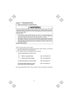
GENERAL PRECAUTIONS
Drawings in this manual may be illustrated without covers or safety shields for explanation of detail parts. Restore the covers and shields in the
original state and observe the description in the manual before starting operation.
ii
How this manual is organized
This manual is made up of chapters 1 through 5.
Chapter 1. BEFORE USING THE COPY ADAPTER
This chapter describes the points to check upon delivery and lists the inverter models, which the copy adapter is designed to interface with.
Chapter 2. INSTALLATIN AND REMOVAL
This chapter describes how to mount and set up the copy adapter and how to set it up with an inverter, as well as how to remove it from the inverter.
Chapter 3. OPERATION USING THE COPY ADAPTER
This chapter describes the functions of the copy adapter, as well as how to use it for data copying.
Chapter 4. MAINTENANCE AND INSPECTION
This chapter describes how to maintain and inspect the copy adapter.
Chapter 5. SPECIFICATIONS
This chapter lists the general specifications such as dimension and operating environments.
Icons
The following icons are used throughout this manual.
This icon indicates information which, if not heeded, can result in the inverter not operating to full efficiency, as well as information
concerning incorrect operations and settings which can result in accidents.
This icon indicates information that can prove handy when performing certain settings or operations.
This icon indicates a reference to more detailed information.
CONTENTS
Preface ................................................ i
Safety precautions ................................ i
How this manual is organized ............. iii
Chapter 1 ............BEFORE USING THE
COPY ADAPTER................1-1
1.1 Acceptance Inspection ..........1-1
Chapter 2 .............. CONNECTION AND
REMOVAL ..........................2-1
2.1 Connection ............................2-1
2.2 Removal ................................2-2
Chapter 3 ..... OPERATION USING THE
COPY ADAPTER................3-1
3.1 Familiarizing Yourself with
the Copy Adapter...................3-1
3.2 Functions of the Copy Adapter
3-2
3.3 Data Copying .........................3-3
iii
Chapter 4 .. INSPECTION AND
MAINTENANCE ................. 4-1
4.1 Periodical Replacement Parts4-1
4.2 Replacing the Connector
Adapter .......................................... 4-2
4.2.1 Disassembling................... 4-2
4.2.2 Reassembling ................... 4-2
4.3 Inquiries about Product and
Guarantee ............................. 4-3
Chapter 5……SPECIFICATIONS .... 5-1
5.1 General Specifications .......... 5-1
Chapter 1 BEFORE USING THE COPY ADAPTER
1.1 Acceptance Inspection
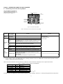
Unpack the package and check that:
(1) The package contains a copy adapter, ten pieces of
connector adapters (for periodical replacement) and its
instruction manual (this book).
(2) There have been no problems during transportation. In
particular, no parts are damaged or have fallen out of
electronic parts nor are there any dents on the body.
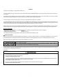
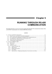
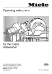
(3) The model name "CPAD-C1A" and SER No. are printed on
the back of the copy adapter as shown in Figure 1.1.
If you suspect the product is not working properly or if you have
any questions about your product, contact your Fuji Electric
representative.
Figure 1.1 Back of Copy Adapter CPAD-C1A
* Type of inverter
For the details of the inverter type identification, refer to the FRENIC-Mini Instruction Manual (INR-SI47-1205-EU), Chapter 1, Section 1.1
"Acceptance Inspection."
1-1
Chapter 2
CONNECTION AND REMOVAL
This chapter guide you how to connect and remove the copy adapter to/from the inverter.
2.1 Connection
• Before connecting the Copy Adapter’s cable connector, first turn off the inverter, wait more than 5 minutes, and make sure that the DC link bus
voltage between the terminals P (+) and N (-) has dropped below the safe voltage level (+25 VDC), using a multimeter.
Otherwise electric shock could occur.
• A high voltage is present on the inverter’s connector CN3 and its neighborhood. Do not touch the CN3 or cable connector while power is
applied.
Doing so could cause electric shock.
To connect the copy adapter to the inverter, follow the steps below.
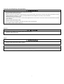
(1) If the wiring to the inverter is completed
First, check that the inverter is powered off.
To remove the control circuit terminal block (TB) cover,
insert your finger tip into the gap at the left of the "PULL"
mark and pull the cover towards you.
If an RS485 communications card (option) is
already mounted, remove it.
For safety, remove all the wirings to the [FWD]
and [REV] terminals.
If the wiring to the inverter is not performed
To remove the control circuit terminal block (TB) cover,
insert your finger tip into the gap at the left of the "PULL"
mark and pull the cover towards you.
Only the wirings to the input terminals L1/R, L2/S and L3/T
will be enough to operate the copy adapter.
Figure 2.1 Removing the TB Cover
For safety, do not wire to the [FWD] and [REV] terminals.
For details of wiring, refer to the FRENIC-Mini Instruction Manual (INR-SI47-0791-EU), Chapter 2 "MOUNTING AND WIRING OF
THE INVERTER."
2-1
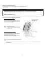
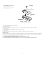
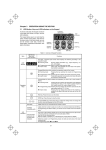
(2)
Connect the cable connector of the copy adapter to connector CN3 on the inverter, with the arrow mark facing up as shown below.
Figure 2.2 Connecting the Cable Connector
(3)
Turn on the inverter power.
2.2 Removal
• Before removing the Copy Adapter’s cable connector, first turn off the power
of inverter, wait more than 5 minutes, and make sure, using a circuit tester
or a similar instrument, that the DC link bus voltage between the terminals P
(+) and N (-) has dropped below a safe voltage (+25 VDC).
Otherwise electric shock could occur.
• A high voltage is present on the inverter’s connector CN3 and its
neighborhood. Do not touch the CN3 or cable connector while the power is
applied.
Doing so could cause electric shock.
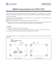
To remove the copy adapter from the inverter, follow the steps below.
2-2
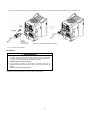
(1) Power off the inverter.
(2) Check that the DC link bus voltage
between the terminals P(+) and N(-)
lowers below the safe level (+25
VDC).
(3) Remove the cable connector from
CN3.
To remove the cable connector,
pinch its outside between your
fingers and pull it towards you.
Pulling it off with the cable
sheath may damage the cable.
Figure 2.3 Removing the Cable Connector
(4) Restore the wirings including the [FWD] and [REV] terminal wires into the original positions.
(5) Set the TB cover back into place.
2-3
Chapter 3 OPERATION USING THE COPY ADAPTER
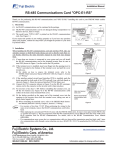
3.1 Familiarizing Yourself with the Copy Adapter
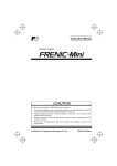
The copy adapter is composed of a
4-digit, 7-segment LED monitor, an
LED block consisting of 5 LEDs, and
6 keys as shown in Figure 3.1.
7-segment LED monitor
LED
indicators
PROGRAM
/RESET key
STOP key
FUNCTION
/DATA key
UP key
DOWN key
Function code
data block No.
key
Figure 3.1 Overview of Copy Adapter
Table 3.1 Names and Functions of Various Parts of Copy Adapter
Monitor,
LED Indicators
and Keys
7-segment
LED monitor
Item
LED
Monitor
Operation
Keys
Function
Remarks
Displays information depending on the operation mode*.
key
Switches the operation mode*.
key
Switches the information displayed, fixes the function code data,
or switches the alarm information displayed, depending on the
operation mode.
This key also enables or disables the data protection function.
key
key
These keys are used to select the setting items displayed on the
LED monitor and change the function code data.
key
This key is used to select the function code data block number.
Out of use for the copy adapter.
(Pressing this key cannot stop the motor in running.)
Lights when any run command is given to the inverter.
Lights when the keypad is specified as a run command source.
key
RUN LED
KEYPAD
CONTROL LED
LED
Indicators
Unit/Mode LEDs
kW, A, Hz, r/min, m/min:
These three LEDs together as a group indicate the unit of the
quantity being monitored.
PRG MODE
Two LEDs (right and left) light in Programming mode.
*Operation mode:
• Running mode
• Programming mode
• Alarm mode
See Table 3.2.
For the operation mode of the FRENIC-Mini and its operating procedures, refer to the FRENIC-Mini Instruction Manual (INR-SI47-1205-E),
Chapter 3 "OPERATION USING THE KEYPAD."
Table 3.2 lists the combinations of the three LEDs on the LED block, which indicate what is displayed on the 7-segment LED monitor.
Table 3.2 Definition of LED Indication on the LED Block
Indication on LED
Hz A kW
Hz A kW
Hz A kW
Hz A kW
Hz A kW
Hz A kW
Hz A kW
Unit
Hz
A
kW
r/min
m/min
-
Description
Frequency
Output current
Input power
Load shaft speed
Line speed
Programming mode
Events other than above
on, off
For details, refer to the FRENIC-Mini Instruction Manual (INR-SI47-1205-E), Chapter 3, Section 3.2.1 " Running mode [1] Monitor the running status."
3-1
3.2 Functions of the Copy Adapter
The copy adapter has the following functions.
Table 3.3 Functions and Operations of Copy Adapter
Function
Run/Stop
Set up
Monitor the inverter
status in idling
Data setting
Data checking
Drive
monitoring
I/O checking
Maintenance
information
Alarm information
Data copying
Description
Remarks
These functions are disabled in the copy adapter.
Pressing the
key or
key sets the set frequency and PID process command, and also sets the
timer.
Items that can be monitored: drive status, output current (A), output voltage (V), timer (s), input power
(kW), PID process command, and PID feedback value.
In speed monitoring, one of the following can be selected:
• Output frequency (before slip compensation) (Hz),
• Output frequency (after slip compensation) (Hz),
• Set frequency (Hz) •
Load shaft speed (r/min),
• Line speed (m/min) •
Constant rate of feeding time (min).
When an alarm condition has occurred, the cause of the trip is displayed as a code.
The function code data is set up and confirmed.
Only the function codes that have been changed from the factory default are displayed or changed
further.
This function is disabled in the copy adapter.
For details, refer to
the FRENIC-Mini
Instruction Manual
(INR-SI47-1205-E)
Chapter 3
"OPERATION
USING THE
KEYPAD."
This function is disabled in the copy adapter.
Certain items are checked or monitored during maintenance.
Certain information such as alarm history is monitored and used in troubleshooting.
• This function reads, writes, and verifies the function code data.
• Ten sets of function code data can be managed with function code data block numbers (#1 to #10).
Refer to Section 3.3.
Conflict between the copy adapter and the built-in keypad on the FRENIC-Mini
When a copy adapter is connected to the FRENIC-Mini, the built-in keypad on the FRENIC-Mini is automatically disabled to avoid conflictions
between them, with the following exceptions (for safety considerations).
The 7-segment LED monitor on the FRENIC-Mini, however, is still displaying the same information as that on the copy adapter.
If data reading is started with the data protection function enabled, the FRENIC-Mini and the copy adapter show read and proT, respectively, on
their 7-segment LED monitors.
3.3 Data Copying
Menu #7 of "Data copying" allows you to read function code data out of FRENIC-Mini inverters (for which function codes have already been set up), to
store the function code data block into another inverter, or to verify function code data, that is, this function compares the function code data saved in
the copy adapter with the one stored in the inverter.
The copy adapter can store up to ten blocks of function code data for ten inverters and protect all data blocks in a lump with the data protection
function.
You need to select a function code data block number by using the
the data into another inverter, or verifying the function code data.
key before reading the function code data out of FRENIC-Mini inverter, writing
The table below details the data copying function and precautions.
Table 3.4 Data Copying Functions
Function
On LED Monitor
Description
Read
data
read
and
Function code data
block number,
displayed
alternately
Reads the function code data out of the inverter’s memory and stores it into the memory of the copy adapter.
key during a read operation (read is blinking), the read operation that is under way will be
If you press the
aborted and errv will appear blinking(*). If this happens, the entire contents of the memory of the copy adapter
will be cleared to zero.
Write
data
copy
and
Function code data
block number,
displayed
alternately
Writes data stored in the memory of the copy adapter into the inverter’s memory.
key during a write operation (copy is blinking), the write operation that is under way will be
If you press the
aborted and err will appear blinking(*). The contents of the inverter’s memory, which are the function code data,
will remain partly old and partly updated. If this happens, do not operate the inverter; instead, perform
initialization or rewrite the entire data.
If any incompatible code is about to be written, cper , will appear blinking. In case this function does not work,
refer to " If you cannot copy function code data": on page 3-9.
Table 3.4 Data Copying Functions (continued)
3-2
Function
Display on LED
Monitor
Description
Verify
data
ueri
and
Function code
data block number,
displayed
alternately
Verifies (collates) the data stored in the memory of the copy adapter with the function code data held in the inverter.
When a discrepancy is detected, the verify operation will be aborted, with the function code in disagreement
key again will cause the verification to continue from the next function code.
displayed blinking. Pressing the
Data
protection
key during a verify operation (ueri is blinking), the verify operation that is under way will be
If you press the
aborted and err will appear blinking(*).
err will appear blinking(*) also when the copy adapter does not contain any valid data.
Protects the memory contents in the copy adapter.
proT
and
When this function is enabled, no data can be read out from the inverter. The data writing and verifying are possible.
Function code
data block number, If you press the
key, err will appear blinking(*).
displayed
alternately
(*)To get out of the error state indicated by a blinking err or cper, press the
key.
Some function code data cannot be copied (stored) into another inverter.
For safety considerations, some function code data cannot be copied to another inverter if the specifications of the destination inverter are
different from those of the source inverter. Which function code data can or cannot be copied is summarized in the FRENIC-Mini Instruction
Manual (INR-SI47-1205-E), Chapter 5, the "Data copy" column of Section 5.1 "Function Code Tables," using the following designations:
Y
:
Can be copied unconditionally.
Y1 :
Cannot be copied if the rated capacity differs from the source inverter.
Y2 :
Cannot be copied if the rated input voltage differs from the source inverter.
N
:
Cannot be copied in any situation. (The function codes marked with N cannot be verified, either.)
Set up manually function code data that cannot be copied individually as necessary, using Menu #1 "Data setting" in Programming mode.
Frequency settings cannot be copied for safety.
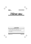
Transition flow
Figure 3.2 shows the status transition flow of the inverter during data copying operation. Figure 3.3 shows the status transition flow to apply when you
select a function code data block number.
The copy adapter can store ten blocks of function code data in the internal memory.
* The selected copy function name and function code data block number appear alternately.
Figure 3.2 Status Transition during Data Copying
3-3
*Also during the copy and ueri operations,
the function name and the function code
data block number appear alternately.
Figure 3.3 Status Transition during Selecting of Function Code Data Block Number
Basic key operation
If the ROM version of your inverter is “CIS10900” or earlier, set function code E52 to "2: Full menu mode" before using the copy adapter.
(1) Turn the inverter on. It automatically enters Running mode. In that mode, press the
menu appears.
(2) Use the
and
keys to display "Data Copying" ('cpy ).
(3)
(4)
(5)
(5)
key to switch to Programming mode. The function selection
key for at least 5 seconds in this state. First, read is displayed for 5 seconds and
To enable the data protection function, hold down the
then proT appears, indicating that the data protection function is enabled.
key to proceed to a list of copying functions (e.g. read ).
Press the
Use the
key to select the desired function code data block number.
Use the
and
keys to select the desired function, then press the
key to execute the selected function. (e.g. read will blink.)
key to return to the data copying function list. Press the
When the selected function has been executed, end appears. Press the
to return to the menu.
key again
The function code data block number selected is preserved even after the copy adapter is removed from the inverter.
Data protection
You can protect all function code data blocks saved in the keypad in a lump from unexpected modifications. Enabling the data protection that was
disabled changes the display read on the Data copying function list to proT, and disables to read data from the inverter.
To enable or disable the data protection function, follow the steps below.
(1)
(2)
Select the data copy 'cpy in the Program mode menu.
Holding down the
key for at least 5 seconds alternates data protection status between enabled or disabled.
• Disabling the enabled Data protection
In the data copying state ('cpy), holding down the
data protection function is disabled.
key for at least 5 seconds first displays proT for 5 seconds and then read, indicating that the
• Enabling the disabled Data protection
In the data copying state ('cpy), holding down the
data protection function is enabled.
key for at least 5 seconds first displays read for 5 seconds and then read, indicating that the
The data protection enabled status is preserved even after the copy adapter
is removed from the inverter.
3-4
Notes in data copying
Do not disconnect the copy adapter from the inverter during data copying.
If you do so, the following problems will arise with the copy adapter and/or inverter depending upon the actual operation being in progress. Take the
necessary action, following the instructions below.
If a data read operation read ) was in progress:
The operation in progress is terminated. The data read and stored in the memory area assigned to the function code data block number currently
selected becomes invalid (the original data is lost). Data write and verify operations thereafter will result in a blinking err display. Mount the copy
adapter again and retry the read operation.
If a write operation copy was in progress:
The operation in progress is terminated. The function code data in the inverter memory is incompletely modified. Do not run the inverter in such
a state. Mount the copy adapter again and retry the write operation or initialize the inverter data.
If a verify operation ueri ) was in progress:
The operation in progress is terminated.
If an error occurs in communication between the copy adapter and inverter during data copying, the "----" appears on the monitor and the following
problems will arise with the copy adapter and/or inverter depending upon the actual operation being in progress. Take the necessary action,
following the instructions below.
If a data read operation read ) was in progress:
The operation in progress is terminated and "----" appears on the monitor. Once the read operation is terminated, the data read and stored in the
memory area assigned to the function code data block number currently selected becomes invalid (the original data is lost). Data write and verify
operations thereafter will result in a blinking err display.
When the communications error is removed, the copy adapter automatically enters the Running mode. So, retry the read operation at this point.
If a write operation copy was in progress:
The operation in progress is terminated and "----" appears on the monitor. The function code data in the inverter memory is modified incompletely.
Do not run the inverter in such a state.
When the communications error is removed, the copy adapter automatically enters the Running mode. So, retry the write operation or initialize
the inverter data.
If a verify operation ueri ) was in progress:
The operation in progress is terminated and "----" appears on the monitor.
When the communications error is removed, the copy adapter automatically enters the Running mode.
If you cannot copy function code data
Check whether the err or cper indicator is blinking.
(1) err is blinking ("Write error"): The following cases can be thought of:
• No data is saved in the memory area assigned to the function code data block number currently selected. (You have not read any inverter
information since delivery or you have aborted a data read operation.)
• Some invalid or abnormal data is contained in the memory area assigned to the function code data block number currently selected.
• The destination inverter type differs from the source inverter type.
• A write operation has been carried out while the inverter is running.
• The inverter is in data protection mode. (F00 = 1)
• The "Enable data change with keypad" terminal command (WE-KP) is off.
• You have attempted to read data when the data protection function is enabled.
Do not run the motor when the copy adapter is connected. Doing so disables the copy adapter from copying data.
• When function code F02 = 1 (External signal), never turn on the terminal command FWD or REV. Doing so operates the inverter so as to
run the motor.
(2) cper is blinking: The following cases can be thought of:
• The function codes stored in the copy adapter are not compatible with those stored in the inverter. Non-standard function code data may have
been stored, or the inverter may have been upgraded in an incompatible manner. Consult your Fuji Electric representative.
3-5
Chapter 4 INSPECTION AND MAINTENANCE
•
•
•
•
Maintenance, inspection, and parts replacement should be made only by authorized persons.
Take off the watch, rings and other metallic materials before starting jobs.
Use insulated tools.
Never modify the inverter or Copy Adapter.
Electric shock or injuries could occur.
4.1 Periodical Replacement Parts
Service life in putting on/off times of the connector adapter mounted at the end of cable connector is limited. This may vary depending on usage
conditions. Table 4.1 below lists its recommended service life for your reference. Ten pieces of the connector adapters (CPAD-C1-CN) come with
the product for periodical replacement. When you become to need more connector adapters (CPAD-C1-CN), consult your Fuji Electric
representative.
Table 4.1
Periodical Replacement Parts
Item
Service life
Connector Adapter
Up to 100 times
If you have experienced frequent communications errors (no response, "----", and er2 ) or copy errors (er1 , err and cper), replace the
connector adapter regardless of its usage times.
Figure 4.1
Connector Adapter
4.2 Replacing the Connector Adapter
4.2.1 Disassembling
(1) Remove the fastening screw and disassemble
the upper cover and the lower cover as shown
in Figure 4.2.
Figure 4.2 Disassembling the Cable Connector
4-1
(2) Remove the connector adapter along the arrow shown in
Figure 4.3.
Pinch the connector between your fingers to
remove the connector adapter. Do not so with
gripping the cable sheath. Doing so may damage
the cable.
Figure 4.3
Removing the Connector Adapter
4.2.2 Reassembling
(1) Place the attached connector adapter with the connector end.
To correctly do so, the orientation marker "A" and "B" shown in
Figure 4.4 should point toward each other. (Note that the
connector and its adapter are illustrated down side up for
convention of showing of their interlocking.)
Figure 4.4
Inserting the New Connector Adapter
(2) Insert the connector with the connector adapter into the lower cover.
The orientation marker "C" on the connector adapter should point toward "D" on the lower cover, contain the lock tie within the lower cover, and
route the harnesses E and F as shown in Figure 4.5.
After completion, recheck that the lock of the connector adapter is placed at the position as shown in G-enlarged in Figure 4.5.
Figure 4.5
Inserting the Connector into the Lower Cover
4-2
(3) Put the upper cover on the lower
cover as shown in Figure 4.6, and
fasten them by the screw.
Note that, no part of the harnesses is
pinched between both covers.
Figure 4.6
Fastening the Covers
4.3 Inquiries about Product and Guarantee
(1) When making an inquiry
Upon breakage of the product, uncertainties, failure or inquiries, report the following information to your Fuji Electric representative.
1)
2)
3)
4)
Copy adapter type
SER No. (serial number of equipment) (Refer to Section 1.1 in this manual.)
Date of purchase
Inquiries (for example, point and extent of breakage, uncertainties, failure phenomena, and other circumstances)
(2) Product warranty
The term of product warranty is one year after the purchase or 18 months from the month and year of production specified on the nameplate,
whichever comes first. However, the product will not be repaired free of charge in the following cases, even if the warranty term has not expired.
1)
2)
3)
4)
The cause includes incorrect usage or inappropriate repair or modification.
The product is used outside the standard specified range.
The failure is caused by dropping, damage or breakage during transportation after the purchase.
The cause is earthquake, fire, storm or flood, lightening, excessive voltage, or other types of disaster or secondary disasters.
4-3
Chapter 5
SPECIFICATIONS
5.1 General Specifications
Table 5.1 summarizes the general specifications of the Copy Adapter "CPAD-C1A."
Table 5.1 General Specifications
Item
Specifications
Environment
Inverter is idle.
No. of connectable unit
One per inverter
Max. cable length
1m
Connection to an inverter
Cable connector
Data storage space
For 10 function code data blocks
(for 10 inverters)
Ambient temperature (during
storage)
-25 to +70C(-13 to 158F)
Ambient humidity (during
storage)
5 to 95% RH (no condensation)
External dimensions
See the figure below.
Weight
155 g
Remarks
For details, refer to the FRENIC-Mini Instruction Manual (INR-SI47-0791-EU), Chapter 2, Section 2.1 "Operating Environment."
External dimensions
(Unit: mm)
5-1
Copy Adapter "CPAD-C1A"
Instruction Manual
First edition, May 2004
Second edition, May 2006
Fuji Electric Co., Ltd.
The purpose of this manual is to provide accurate information in the handling, setting up and operating of Copy Adapter "CPAD-C1A" for the FRENIC-Mini
series of inverters. Please feel free to send your comments regarding any errors or omissions you may have found, or any suggestions you may have for
generally improving the manual.
In no event will Fuji Electric FA Components & Systems Co., Ltd. be liable for any direct or indirect damages resulting from the application of the
information in this manual.
MEMO
Fuji Electric Systems Co., Ltd.
Fuji Electric Corp. of America
47520 Westinghouse Drive Fremont, CA 94539, U.S.A.
Tel.+1-510-440-1060 Fax.+1-510-440-1063
Toll-free support 1-888-900-FUJI(3854)
INR-SI47-0886a-EU Rev 052010
http://www.fujielectric.com/fecoa/
Information subject to change without notice.