1
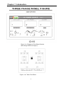
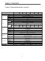
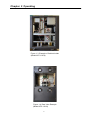
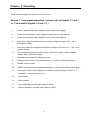
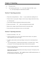
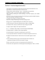
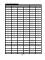
Intepro Systems
AFC Series
IGBT - Type
USER MANUAL
©2015 All rights reserved by Intepro Systems
Version 1
Version History
Version
No.
V1.0
Release
date
3-2015
Writer
Description
Rev 1
Hardware
version applied
Intepro Systems provides a full range of technical support for our customers. Customers can
contact our offices or customer service centers nearby, or our headquarters. All rights reserved.
This manual is subject to change without notice.
Safety Precautions
Danger
Beware o f the high temperature of this equipment. DO NOT open the chassis without
technician present or authorization from Intepro Systems.
• When the AFC needs to be moved or rewired, please shut down the instrument completely
by disconnecting the input power lines and wait at least 20 minutes for the capacitors in the
instrument to discharge to prevent electric shock.
•
In order to ensure the personal safety of users, this series of power products must be grounded
before use.
• In case of fire, please use dry powder fire extinguishers instead of liquid fire extinguishers
to avoid the risk of electric shock.
•
Liquid or other foreign objects must not be allowed to enter the cabinet of the grid simulator.
Attention
The application environment and storage methods affect the service life and reliability of the
product. Extended use in the following conditions should be avoided:
• Ambient high or low temperatures or humidity beyond technical specifications (temperature:
-20℃to 40℃; relative humidity: 5% to 95%);
•
In direct sunlight or exposed to heat sources;
•
Places susceptible to vibration or collision;
•
Environments with dust, corrosive substances, salt and combustible gases;
Keep the air inlets and outlets unblocked to promote ventilation to avoid a rise in the internal temperature, which
may shorten the service life of components, and affect the service life of the product;
Grid simulators not in service for a long time should be stored in a dry environment. The temperature
range for storage is -40℃to 70℃.
To properly protect the equipment, only the personnel of Intepro Systems are allowed to open the
front door or side cover. If the quality assurance seal is broken, required services will incur charges
and guaranty is void.
Danger: conditions that may cause serious equipment damages or human casualties.
Attention: Conditions that may cause moderate injuries or damages to equipment.
Content
Content.........................................................................................................................1
1 Introduction............................................................................................................2
1.1
Equipment description...................................................................................2
1.2
Equipment diagram..................................................................................... 2
1.3
Equipment specification................................................................................ 4
2 Operating .............................................................................................................. 6
2.1 Front panel instruction ......................................................................................8
2.2 Operating procedure........................................................................................ 9
2.3 Operating instruction........................................................................................9
3 Functional instructions ......................................................................................... 11
3.1 The whole function diagram................................................................................... 11
3.2 Functional diagram instruction................................................................................12
4 Troubleshooting...................................................................................................... 13
4.1 Introduction.............................................................................................................13
4.2 Troubleshooting chart.............................................................................................13
5 Equipment maintenance ........................................................................................15
5.1 Moving.....................................................................................................................15
5.2 Positioning................................................................................................................15
5.3 Maintenance............................................................................................................15
5.4 After Sales Service................................................................................................... 16
6 Special Optional Function Specifications ..............................................................17
Additional Specifications ............................................................................................18
Warranty Card ..............................................................................................................21
1
Chapter 1 Introduction
Preface
Intepro Systems would like to express our thanks for your purchase of our AC Power Source
with its state-of-the-art technology and highly effective components. This manual explains
how to install, operate and maintain the server correctly to get the best performance from
the unit. Please read this manual carefully before installing and keep it near the unit for
reference during operation.
All information in this manual is copyrighted by Intepro Systems. Information included in this
manual should be only for user's reference and is subject to change without notice. Intepro
is not responsible for any damage, mistakes or losses caused by acting outside the
guidance of this manual.
Section 1. Equipment Description
The AFC series converters are highly effective and advanced technology. As such, the AC
power source provides not only a pure and stable sine wave, but is protection for overtemperature, overload, and over-voltage with an inner controlling circuit.
Section 2. Equipment Diagram
1. Please refer to Figure 1-1 for an example Front Panel view (Model AFC-11010 shown).
2. An example Equipment Overview is shown in Figure 1-2.
3. Examples of the inside of the cabinet from the front and the rear are shown in Figures
1-3 and 1-4
Figure 1-1 Front Panel View Example
2
Chapter 1 Introduction
Figure 1-1a Diagram of Front Panel Controls
(See listing of labels on Page 8)
Figure 1-1b Three Front Panel
3
Chapter 1 Introduction
Section 3. Equipment Specification
Model
Capacity (kVA)
Circuit Type
Phase
Wave
Voltage
Input
Output
System
Voltage Range
Frequency Range
Power Range
Phase
Wave
Low
Voltage
High
Frequency
Frequency regulation
High(A)
Max
Current
Low (A)
Line Regulation
Load Regulation
Total harmonic
distortion (THD)
Efficiency
Response Time
Crest Factor
Protection Device
Display
Voltage
Current
Indicator
Power
Frequency
Insulation equipment
Withstand voltage
insulation
EnvironCooling system
mental
Temperature
Humidity
Altitude
Case Number
Weight (Lb/Kg)
AFCAFC11500W
11001
0.5
1
Transistor Amplifier
AFC11002
2
AFC11003
3
110V,120V,220V
OR 277V
110V,120V,220,277
V±15%
4.2
8.4
AFCAFC11008
11010
8
10
IGBT/PWM type
Single Phase
Sine Wave
AFC11015
15
AFC11020
20
AFC11030
30
120V/208V, 220V/380V, OR 277V/480
120V±15%, 220V±15%, or 277V±15%
0~150V (L-N)
0~300V (L-N)
2.1
4.2
AFC11005
5
8.3
16.7
0.5%
±0.5%
50Hz±3Hz or 60Hz±3Hz
0.85
Single Phase
Sine Wave
5V~150V (L-N)
10V~300V (L-N)
47~63Hz, 50Hz, 60Hz; 2F, 4F, 400Hz (Option)
0.01%
12.5
20.8
33.3
41.7
25
41.7
66.7
83.3
<1%
<±1% (Linear Load)
62.5
125.0
83.3
166.7
125.0
250.0
<2% (Linear Load)
0.5%
70%
50 µ s
1.4 : 1
Same as AFC11002 plus output
no fuse breaker
90%
50ms
3:1
Input no fuse breaker, electronic circuit instant trip for over/low voltage, over current, over
load, over temperature, and short circuit protection and alarm system
LED
Show Range: 0~600V, resolution 0.1V, accuracy: 0.15%FS+4Count
Show Range: 0~700A, resolution 0.01A (<100A) / 0.1A ( 100A),
accuracy: 0.15%FS+4Count
Show Range: 3kW~75kW, resolution 0.01kW (<10kW) / 0.1kW ( 10kW),
accuracy: 0.3%FS+4Count
Show Range: 0~999.9Hz, resolution 0.1Hz, accuracy: 0.1%
DC500V 10MΩ
Resolution 0.1V
0.001A
0.01A
0.1W
1W
Resolution 0.1Hz
AC 1800V 10mA/1 Min
Fan Cooling
0°C ~ 45°C
0 ~ 90% (Non-condensing)
1500m
1
97/44
2
195/89
150/68
160/73
4
195/89
440/200
3
460/210
4
530/240
615/280
725/330
Chapter 1 Introduction
Section 3. Equipment Specification, continued
Model
Capacity
Circuit Type
Input
Output
System
Phase
Wave
Voltage
Voltage range
Frequency range
Power factor
Phase
Wave
Voltage
Low
High
Frequency
Frequency
regulation
Max
High
Current
(A)
Low
(A)
Line regulation
Load regulation
Total harmonic
distortion (THD)
Efficiency
Response Time
Crest factor
Protection device
Indicator
Power
Case No.
Weight (Lb/Kg)
AFCAFC-31045
AFC-31060
31030
30
45
60
IGBT/PWM type
Three phase
Sine Wave
120V/208V, 220V/380V, OR 277V/480V
120V/208V±15%, 220V/380V±15%, or 277V/480V±15%
50Hz±3Hz or 60Hz±3Hz
0.85
Single phase
Sine
5V~150V (L-N)
10V~300V (L-N)
47~63Hz, 50Hz, 60Hz; 2F, 4F, 400Hz (Option)
10
Display
Voltage
Current
Environmental
AFC31015
15
AFC-31010
Frequency
Insulation
resistance
Withstand voltage
insulation
Cooling System
Temperature
Humidity
Altitude
AFC31020
20
AFC-31075
75
0.01%
47.1
62.5
83.3
125.0
83.3
125.0
166.7
250.0
<1%
<±1% (Linear Load)
187.5
250.0
312.5
375.0
500.0
650.0
<2% (Linear Load)
90%
50ms
3:1
Input no fuse breaker, electronic circuit instant trip for over/low voltage, over current, over load, over
temperature, and short circuit protection and alarm system
LED
Show Range: 0~600V, resolution 0.1V, accuracy: 0.15%FS+4Count
Show Range: 0~700A, resolution 0.01A (<100A) / 0.1A ( 100A),
accuracy: 0.15%FS+4Count
Show Range: 3kW~75kW, resolution 0.01kW (<10kW) / 0.1kW ( 10kW),
accuracy: 0.3%FS+4Count
Show Range: 0~999.9Hz, resolution 0.1Hz, accuracy: 0.1%
DC500V 10MΩ
3
460/210
530/240
5
AC 1800V 10mA/1 Min
Fan Cooling
0°C ~ 45°C
0 ~ 90% (Non-condensing)
1500m
4
640/290
750/340
1190/540
5
1340/610
1470/670
Chapter 2 Operating
Figure 1-2 Equipment Overview Example (Model AFC-11010 shown)
6
Chapter 2 Operating
Figure 1-3 Example of Cabinet Inside
(Model AFC-11010)
Figure 1-4 Rear View Example
(Model AFC-11010)
7
Chapter 2 Operating
Please follow the steps of this manual to turn on the unit.
Section 1. Front panel instruction(please refer to Figures 1-1 and 11a, 1-1b as well as Figures 1-2 and 1-3)
「1」- Output voltage display meter: displays output voltage value digitally.
「2」- Output frequency display meter: displays output frequency value digitally.
「3」- Output current display meter: displays output current value digitally.
「4」- Upper limit voltage fine adjustment knob: setting voltage in the upper 10﹪~ 25﹪of
the standard voltage.
「5」- Lower limit voltage fine adjustment knob: setting voltage in the lower 10﹪~ 30﹪of the
standard voltage.
「6」- Three-segment voltage select switch: upper- upper limit voltage, middle- standard
voltage, lower- lower limit voltage.
「7」- Standard output voltage fine adjustment knob
「8」- Frequency select switch: fixed frequency 50 Hz to 60Hz and variable frequency.
「9」- Variable frequency knob.
「10」- RESET button::t:he button to postpone starting-up or reset for shut down,, buzzer alarm.
「11」-Three phase output current display select switch: selecting display of the R-S-T of
each phase(only in three phase unit).
「12」- Input breaker.
「13」- Output breaker.
「14」- Input Copper Bar: provides input cable for wiring.
「15」- Output Copper Bar: provides output cable for wiring.
8
Chapter 2 Operating
「16」- Emergency button.
「17」- HI/LO selecting switch: press 「HI」 then output voltage 10V~300V;press
「LO」then output voltage 5V~150Vcontinuous variable.
Section 2. Operating procedure
1. Please refer to the specifications ( Table 1.) for your model before installing the unit.
2. Please check the input power voltage is correct using a voltage meter before turning
on the input power.
3. Turn the output voltage fine adjustment knob around the minimum
4. Please turn the breaker 「OFF」 before connecting the input power cable.
5. Make sure the voltage is as specified and connect the input power cable.
6. Once connections and settings are correct, turn on the power.
Section 3. Operating instruction
1. Please turn the breaker「OFF」first.
2. Check the switches of the unit by turning various function knobs on the panel to
inspect whether they are loose or tight.
3. For safety, please make sure the input voltage is correct prior to connecting the input
power.
4. Turn on the input power. The alarm should sound after 3 to 5 seconds. Press 「Reset」
on the panel. The unit will supply output voltage(device start-up is gradual.
5. Select the output frequency. You can select the frequency any time without turning off the
unit, but turn off the load first.
Fixed frequency output: directly switches to the setting on the panel. The frequency of the
display meter is the output.
Variable frequency output::select 「VAR」and thenfine adjust the VAR (variable frequency)to
the output frequency needed using the knob .
9
Chapter 2 Operating
For example,the required frequency is 55 Hz, switch「VAR」first, and fine adjust the
variable frequency knob until the frequency is up to「55」.
6. Standard output voltage adjustment:switch the 「Three-segment voltage select switch to
the standard position..Then fine adjust the「standard output voltage adjustment knob」to
s e t the required output voltage.
7. Upper limit voltage adjustment: switch t h e 「Three-segment voltage select switch」to the
upper position. Then fine adjust the upper right side knob using a small screwdriver to
acquire the required output voltage.
8. Lower limit voltage adjustment: switch the 「Three-segment voltage select switch」to the
lower position. Then fine adjust the down-right side knob using a small screwdriver to
acquire the required output voltage.
9. After verifying the above steps are correct, the load can be connected to the terminal .
block of the unit
Remarks:
This unit includes output overload and short-circuit protection. If an output overload or
short-circuit occurs, this protection will cut down the output power and sound an alarm.
When this occurs, please turn off the load and press 「Reset」 to stop the alarm. When
the alarm is stopped, please confirm the output voltage is normal and turn on the load.
10
Chapter 3 Function Instruction
Section 1.
The whole function diagram
11
Chapter 3 Function Instruction
Section 2. Function diagram instruction
1.Input power: the connection from the power terminal to the input terminal block of unit.
2.Input breaker: controls the electricity to connect the unit.
3. Escape switch: protector with sag、surge、overload and over-temperature.
4. Rectifier and filter: to convert AC voltage to stable DC voltage.
5. OSC frequency switching: the select switching of the fixed frequency and variable
frequency.
6. Frequency mixing: the signal processing of the fixed frequency and the variable frequency.
7.Sine wave generator: generates sine wave.
8. Triangle wave generator: generates triangle wave.
9.Wave form mixing: PWM mixing of sine wave and triangle wave.
10.Driver circuit: To amplify PWM signal to drive IGBT power component.
11.IGBT active power component: generates output voltage (includes PWM).
12.Transformer filter: steps up and filters the output voltage of the IGBT.
13. Output: outputs voltage to the output terminal block.
14. V、A、Hz display: output voltage, current and frequency digital display.
15.Voltage feedback: to stabilize output voltage amplitude.
16. Overload detective: feeds back overload signal to control circuit.
17. Over-temperature detective: feeds back over-temperature signal to control circuit.
18.FUSE circuit breaker detector: feeds back fuse circuit breaker signal to control
circuit.
19. Start-up/escape protection circuit: receives the signal of the overload, overtemperature and trips the FUSE circuit breaker to escape.
20. Alarm: sounds when overload, over-temperature and fuse break occur
21. Reset: when the equipment is cut off and tripped automatically,press「Reset」to restart.
12
Chapter 4. Troubleshooting
Section 1. Introduction
Our qualified product must have passed the test calibration and detailed inspection by our
Quality Assurance staff.
If the unit cannot operate normally, which may be caused by the environment, person or
other unknown factors, please follow the steps outlined in the troubleshooting chart.
Section 2. Trouble shooting chart
NO.
Description
Analysis
Solution
The utility is abnormal, or
connection is abnormal
Check the utility and the phase sequence of
input voltage, eliminate the errors, and restart.
Input under-voltage
Check the input voltage, eliminate the
errors, and restart
①
②
R phase module error;
R phase circuit short.
Please contact our service department or
salesperson..
4
Connect the utility to the input, but
cannot RESET. At this time, LED
indicator displays “06” in the
protection board.
③
①
S phase module error;
S phase circuit short.
Please contact our service department or
salesperson.
5
Connect the utility to the input, but
cannot RESET. At this time, LED
indicator displays “05” in the
protection board.
④
①
T phase module error;
T phase circuit short.
Please contact our service department or
salesperson.
6
Connect the utility to the input, but
cannot RESET. At this time, LED
indicator displays “08” in the
protection board.
7
Connect the utility to the input, but
cannot RESET. At this time, LED
indicator displays “02” in the
protection board.
8
Connect the utility to the input, but
cannot RESET. At this time, LED
indicator displays “01” in the
protection board.
9
Connect the utility to the input, but
cannot RESET. At this time, LED
indicator displays “03” in the
protection board.
The temperature protection circuit is
abnormal
Check if the internal temperature is
abnormal in the temperature control switch
and the circuit. Eliminate the errors, and
restart.
10
There is something wrong with the
fans
There is something in the air
channel
Clear air channel
11
Display function is abnormal
Check that errors exist in the tables,
or the sample circuit is abnormal.
1
Does not start up, and no response
2
Connect the utility to the input, but
cannot RESET. At this time, LED
indicator displays “04” in the
protection board.
3
Connect the utility to the input, but
cannot RESET. At this time, LED
indicator displays “07” in the
protection board.
Overload
Disconnect unnecessary load and restart.
Internal FUSE has blown
Check whether the fuse has blown. If it did,
please contact our service department or
salesperson
The output is over-voltage
Please contact our service department or
salesperson.
13
Replace the tables and check the sample
circuit.
Chapter 4. Trouble shooting
Common faults code table
Fault code
Cause
Fault code
Cause
IGBT over-current in
T phase
IGBT over-current in
S phase
IGBT over-current in
R phase
00
Start normally
05
01
R、S、T phase
over-voltage
06
02
Fault on the fuse breaker
07
03
Over-temperature
08
overload
04
Input under-voltage
c0
External error
When you contact our service department or salesperson, please provide the common fault code
displayed by the LED indicator in the protection board. You will also need the model and serial
number of the equipment.(see the rear of the chassis).
14
Chapter 5
Equipment maintenance
Regular and correct maintenance is essential to extend the life time of the equipment.
Section 1. Moving
1. Power off the input power source (breaker or switchboard) connected to the unit and
disconnect all cables.
2. Do not move the converter while upside down.
3. Handle with care and avoid collisions.
Section 2. Positioning
1. Do not place the converter on uneven ground or slopes.
2. Keep the unit away from direct sunlight, rain or high humidity.
3. Keep the unit away from fire or other heat sources to avoid overheating.
4. For proper ventilation, position the converter with at least 6 inches (10 cm) clearance at
rear panel and wall.
5. The working temperature is 0~45℃, humidity of 10~90%.
6. Keep the unit away from corrosive gases or liquids.
Section 3. Maintenance
1. Keep the working place clean and dry to prevent rodents in the unit.
2. Verify whether the function of the converter is correct.
3. Do not allow anything to rest on the power cord to avoid inadvertent damage or hazards
that may occur. Avoid locating the power cord in high traffic areas.
4. Never put any kind of objects into the unit through the ventilation openings as they may touch
dangerous voltage points or short out parts that could result in fire or electrical shock.
5. Service to the unit should be done by factory-trained person only. Opening or removing
covers may expose dangerous voltage points or other hazards.
15
Chapter 5
Equipment maintenance
Section 4. After - Sales Service
Intepro Systems provides a full range of technical support to customers. Customers are encouraged to
contact our branch office or our technical personnel when you have purchased our product.
For the details of warranty, please refer to the terms of warranty. We provide paid customization service
packages at different levels, including fast response, preventive maintenance, and warranty renewal service.
Please contact the local service centers of our company.
•
Service Telephone
USA: +1.714.953.2686
UK/Europe: +44.1251.875600
Asia: +86.755.86500020
•
On-line technical service: www.InteproATE.com
•
Intepro Systems America, LP
14712-A Franklin Avenue
Tustin, CA 92780
USA
Tel: +1.714.953.2686
Fax: +1.714.673.6567
16
Chapter 6
Special Optional Function
□ Adding terminals for remote control
a n d terminals
for remote control specification:
Remote control terminal panel
Input DC4-20mA at 1,2; control output voltage.
●
Choose exterior(EXT) to control voltage
●
Connect 1 to positive, connect 2 to negative
●
No output voltage will be generated if wrong positive and negative connection occurs
3,4,5 Control output frequency:
● (EXT) choose exterior (EXT) to control frequency
● When short circuit occurs at 3,4, output frequency is 50Hz
● When short circuit occurs at 4,5, output frequency is 60Hz
● When short circuit occurs at 3,4,5, output frequency is adjustable; ( VR controls the
frequency through adjustment on the panel)
6,7 Alert control signal:
Short circuit occurs at 6、7: When the machine is in a normal state and the machine
alerts and buzzer sounds, the open circuit has taken place at 6,7.
8,9: Signal at high voltage and low voltage contact joint
● When idle connection occurs at 8、9, output voltage is 5-150V(low)
。
● When short circuit occurs at 8、9, output voltage is 10-300V(high)
。
10. Screen grounding terminal
17
Additional Specifications
Model
AFC
Input:△ 380V , Y 220V/380V
Input
Imax
NFB
Cable
□1.5k
4A
10A
0.6mm
2
□ 2k
5A
10A
0.6mm
2
□ 3k
7A
10A
0.75mm
□ 5k
12A
15A
1.25mm
□ 6k
14A
15A
2.0mm
2
□7.5k
18A
20A
3.5mm
2
□ 8k
19A
30A
3.5mm
2
□10k
24A
30A
5.5mm
2
□15k
36A
40A
8.0mm
2
□20k
48A
50A
14.0mm
□30k
72A
75A
22.0mm
□45k
108A
125A
50.0mm
□60k
144A
200A
80.0mm
□100k
212A
250A
120.0mm
2
2
2
2
2
2
2
Output1ψ
Output
Imax
Cable
LO:12.5A
2
1.25mm
HI:6.25A
LO:16.7A
2
3.5mm
HI:8.3A
LO:25.0A
2
5.5mm
HI:12.5A
LO:41.7A
2
8.0mm
HI:20.8A
LO:50.0A
2
14.0mm
HI:25.0A
LO:62.5A
2
22.0mm
HI:31.3A
LO:66.7A
2
22.0mm
HI:33.3A
LO:83.3A
2
30.0mm
HI:41.7A
LO:125.0A
2
50.0mm
HI:62.5A
LO:166.7A
2
80.0mm
HI:83.3A
LO:250.0A
2
150.0mm
HI:125.0A
LO:375.0A
2
120mm *2
HI:187.5A
LO:500.0A
2
120mm *3
HI:250.0A
LO:833.3A
2
120mm *4
HI:416.7A
□
Model
AFC
Input:△ 220V , Y 128V/220V
Input
Imax
NFB
Cable
2
□10K
41A
50A
8.0mm
□15k
61A
75A
14.0mm
□20k
82A
90A
22.0mm
□30k
122A
125A
38.0mm
2
2
2
□
Table 1-
18
Output1ψ
Output
Imax
Cable
LO:83.3A
2
22.0mm
HI:41.7A
LO:125.0A
2
38.0mm
HI:62.5A
LO:166.7A
2
80.0mm
HI:83.3A
LO:250.0A
2
150.0mm
HI:125.0A
Additional Specifications
Model
AFC
Input:△ 220V , Y 128V/220V
Input
Imax
NFB
Cable
□1.5k
11A
15A
2.0mm
2
□2k
15A
20A
3.5mm
2
□3k
20A
30A
3.5mm
2
□5k
35A
40A
8.0mm
2
□6k
43A
50A
14.0mm
□7.5k
53A
60A
14.0mm
□8k
57A
60A
22.0mm
□10k
65A
100A
22.0mm
□15k
98A
150A
38.0mm
□20k
142A
200A
60.0mm
□30k
213A
300A
100.0mm
2
2
2
2
2
2
2
Output1ψ
Output
Imax
Cable
LO:12.5A
2
1.25mm
HI:6.25A
LO:16.7A
2
3.5mm
HI:8.3A
LO:25.0A
2
5.5mm
HI:12.5A
LO:41.7A
2
14.0mm
HI:20.8A
LO:50.0A
2
14.0mm
HI:25.0A
LO:62.5A
2
22.0mm
HI:31.3A
LO:66.7A
2
22.0mm
HI:33.3A
LO:83.3A
2
30.0mm
HI:41.7A
LO:125.0A
2
50.0mm
HI:62.5A
LO:166.7A
2
80.0mm
HI:83.3A
LO:250.0A
2
120.0mm
HI:125.0A
□
Model
AFC
Input:△ 220V , Y 128V/220V
Input
Imax
NFB
Cable
□ 3k
12A
15A
2.0mm
2
□ 6k
24A
30A
5.5mm
2
□10k
41A
50A
8.0mm
2
□15k
60A
75A
14.0mm
□20k
82A
90A
22.0mm
□30k
122A
125A
38.0mm
2
2
2
□
Table 1-2
19
Output3ψ
Output
Imax
Cable
LO:8.3A
2
1.5mm
HI:4.2A
LO:16.7A
2
3.5mm
HI:8.3A
LO:27.8A
2
5.5mm
HI:13.9A
LO:41.7A
2
8.0mm
HI:20.8A
LO:55.6A
2
14.0mm
HI:27.8A
LO:83.3A
2
22.0mm
HI:41.7A
Additional Specifications
Model
AFC
Input:△ 380V , Y 220V/380V
Input
Imax
NFB
Cable
□1.5k
4A
10A
0.6mm
2
□ 2k
5A
10A
0.6mm
2
□ 3k
8A
10A
0.75mm
□ 5k
12A
15A
1.25mm
□ 6k
14A
15A
2.0mm
2
□ 8k
19A
30A
3.5mm
2
□10k
24A
30A
5.5mm
2
□15k
36A
40A
8.0mm
2
□20k
48A
50A
14.0mm
□30k
72A
75A
22.0mm
□45k
108A
125A
38.0mm
□60k
150A
150A
60.0mm
□75k
180A
187.5A
100.0mm
□90k
216A
225A
120.0mm
2
□100k
240A
250A
150.0mm
2
□120k
283A
300A
200.0mm
2
□150k
354A
400A
120mm *2
□200k
472A
500A
120mm *2
□300k
707A
800A
120mm *3
□400k
998A
1000A
120mm *5
□500k
1248A
1300A
120mm *6
□600k
1497A
1500A
120mm *7
2
2
2
2
2
2
2
2
2
2
2
2
2
Table 1-3
20
Output3ψ
Output
Imax
Cable
LO:4.2A
2
0.6mm
HI:2.1A
LO:5.6A
2
0.6mm
HI:2.8A
LO:8.3A
2
0.9mm
HI:4.2A
LO:13.9A
2
2.0mm
HI:6.9A
LO:16.7A
2
3.5mm
HI:8.3A
LO:22.2A
2
5.5mm
HI:11.1A
LO:27.8A
2
5.5mm
HI:13.9A
LO:41.7A
2
8.0mm
HI:20.8A
LO:55.6A
2
14.0mm
HI:27.8A
LO:83.3A
2
22.0mm
HI:41.7A
LO:125.0A
2
38.0mm
HI:62.5A
LO:166.7A
2
60.0mm
HI:83.3A
LO:208.3A
2
100.0mm
HI:104.2A
LO:250.0A
2
150.0mm
HI:125.0A
LO:277.8A
2
150.0mm
HI:138.9A
LO:333.3A
2
200.0mm
HI:166.7A
LO:416.7A
2
120mm *2
HI:208.3A
LO:555.6A
2
120mm *3
HI:277.8A
LO:833.3A
2
120mm *4
HI:416.7A
LO:1111.1A
2
120mm *5
HI:555.6A
LO:1388.9A
HI:694.4A
LO:1666.7A
HI:833.3A
2
120mm *6
2
120mm *7
Quality
Service
Innovation
Warranty Card
Dear
,
Thanks for your support and patronage. This card is to ensure that in case the grid simulators you have
purchased (model: ____________, serial number:
fail
in
normal conditions of use within a year because of the process error or component deterioration, Intepro
Systems, LP. will have responsibility to provide after-sales service for free.
Please note:
The machine is required to be installed and used properly. Do not modify the structure, circuit or
component.
1. If the machine has faults, please call us or pack the machine properly and indicate the faults before
sending back to our company. We will serve you as soon as possible.
2. If the warranty period expires, and the customer keeps the card, we will charge a reasonable fee after the
completion of repair.
Attn:
Date:
21