1
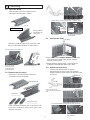
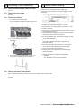
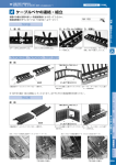
Tsubaki
User Manual
®
Cableveyor
PAT.
TKC34H25・TKC47H36・TKC64H50・TKC85H68
(formerly TKC0340),
(formerly TKC0470),
(formerly TKC0640),
(formerly TKC0850)
Thank you for your purchase of the Tsubaki Cableveyor.
These instructions cover everything from delivery to installation. Please
read them thoroughly before starting.
Arm snap
1 Construction/Part Name
Arm
Arm hinge
Moving end bracket
Link (A)
(Bracket connects to the link outer face)
Lock stay
Divider
Link (B)
Fixed end bracket
(Bracket connects to the link inner face)
Sectioned Cableveyor
2 Delivery
Arm
1)
A. For TKC34H25
The moving end bracket is delivered assembled into the Cableveyor unit,
while the fixed end bracket and dividers are shipped as unassembled
parts.
B. For TKC47H36, TKC64H50, and TKC85H68
Both the moving and fixed end brackets are delivered assembled into the
Cableveyor unit, while the dividers are shipped as unassembled parts.
Moving end bracket
Fixed end bracket*
2) Long length Cableveyors (usually over 4m) are
generally shipped in sections.
*Delivered as unassembled parts for
TKC34H25.
1
3 Connecting
3-1 Open the arms.
Open the arms one by one starting from the
Cableveyor travel end (Dia. 1 below).
.
*Guide mark for removing locking stays (screwdriver mark)
Mark
Open starting
from one
Mark
Insert
screwdriver
here
Fixed end bracket
Moving end bracket
Connected from the
outer link face
For TKC34H25
Insert
screwdriver
here
For TKC47H36, TKC64H50,
and TKC85H68
3-3 Connect the links.
Tap lightly
There is a screwdriver mark on the arm snaps. Insert
the tip of a flat-head screwdriver to open the arms.
Open sequentially from the travel end
To remove
To attach
Bend slightly and overlay
1) Align the pin hole and stopper projection and forcefully
press in the link by hand. A light tap with a plastic
hammer will also suffice.
*1. Screwdriver tip size
TKC34H25=4.5mm
TKC47H36=6.0mm
TKC64H50=8.0mm
TKC85H68=8.0mm
2) Slightly bend the stopper knobs on the links about
5 degrees toward bending radius side to align.
*2. Arms can be removed by lifting
80 degrees and pulling out.
3-4 Attach the lock stays.
Insert the lock stay into links (A) and (B)
simultaneously as shown in the cross-sectional
diagram below and press down in the direction of the
arrow to fix.
Push down
3-2 Remove the lock stays.
Remove 3 or 4 lock stays from the area to be
connected on the travel end side.
Moving end bracket
Lock stay
Link
Note: Align the lock stay
in links (A) and (B) at the same
time.
Push down
Opened arm
Removed lock stays
*Lock stay attachment guide mark (to align with links)
Insert a flat-head screwdriver into the grooves of lock
stays with a screwdriver mark and pry open in the
direction of the arrow.
For TKC34H25
2
For TKC47H36, TKC64H50,
and TKC85H68
4-4 Close the arms.
4 Inserting Cables/Hoses (set)
Close the arms from the Cableveyor fixed end side. Press
down firmly on the mark on the arm surface by hand, or
lightly tap with a plastic hammer, to connect the arm to the
link (B). (Note: Tapping the highlighted area below with
a hammer may cause cracking.)
4-1 Open the arms.
Refer to 3-1.
4-2 Attach the dividers.
Press firmly
Movable side
Push
down
Do not tap
the arm here.
Vertical
divider
Locking side
Lock stay
Note: Close the arms sequentially from the fixed end.
1) There are two ways to attach the vertical divider to
the lock stay.
A. For fixed dividers
Position the vertical divider with the LOCK arrow facing
down and connect to the lock stay to fix in place.
Dividers can be fixed along the stay in 5mm increments.
B. For movable dividers
Position the vertical divider with the LOCK arrow facing
up. Dividers can slide freely along the lock stay groove.
With cables/hoses inserted (set)
2) Align the vertical divider with the lock stay recess
and press firmly by hand to attach.
5 Lengthening Your Cableveyor
3) Attaching the dividers
Dividers should generally be attached every other
link.
5-1 Remove the travel end bracket.
Insert a flat head screwdriver between the link and
bracket and remove the bracket, or remove the first
link. (See 6.)
4) To remove the vertical divider from the lock stay,
push the divider down laterally.
5-2 Connect the additional link(s).
Attach
First, lightly tap links (A) & (B) with a plastic hammer
to connect.
Remove
Tap lightly
Tap lightly
Lock stay
4-3 Insert the cables/hoses.
Insert the cables/hoses into their designated position.
5-3 Attach lock stays to the additional link(s).
See 3-4.
5-4 Attach any dividers and arms.
See 4-2.
5-5 Attach the travel end bracket.
Tap lightly
3
6 Shortening Your Cableveyor
6-1 Remove arms from the travel end side.
See 3.1.
6-2 Remove the lock stays.
7 Caution when Handling
Depending on the application, there may be sag or
pretension in the self support length. Select your
Cableveyor using Tsubaki's Performance Graph to avoid
any issues.
See 3-2.
6-3 Remove the link(s).
1. For TKC34H25 and TKC85H68
Insert a flat-head screwdriver between the links to
separate. Perform the same on the brackets.
2. For TKC47H36 and TKC64H50
Insert a flat-head screwdriver between the links
to separate.
Fixed end bracket
Moving end
bracket
Guide rail
1. The travel end installation height (H') to the equipment
should be the Cableveyor's height H + (10-30).
2. The Cableveyor mounting height (h) should be H + 100.
3. Install a guide rail.
4. The error (ε) in travel end and fixed end installation faces
should be less than 6mm.
5. Use cables/hoses designed for movement with excellent
bending and wear resistance properties.
6. Do not use cables/hoses with wire braid casings, as they
can be easily damaged.
7. Stacking cables/hoses can easily cause wear. Cables/
hoses should be laid horizontally or separated by
horizontal dividers.
8. Ensure the cables/hoses have leeway in their length
when installing. After adjusting them to the proper
length, secure both ends with clamps.
9. Foreign matter in the guide rail may cause damage.
Please keep clean.
3. Or, instead of using a screwdriver place a jig on
the link pins and lightly tap with a hammer.
Hammer
10. The following parts are delivered unassembled.
・Dividers
・(For TKC34H25 only): Fixed end bracket
Jig
6-4 Remove the travel end bracket.
Insert a flat-head screwdriver between the link and bracket to remove the bracket.
6-5 Attach the travel end bracket.
See 5-5.
Chain 椿本チエ
Co.
4 Issued October 1, 2012
2012 年 ©Tsubakimoto
10 月 1 日発行 ©株式会社