1
User’s
Manual
DTSXL
Distributed Temperature Sensor
Long Range System
Read Me First
IM 39J06A40-01E
This User's Manual (this "Manual") contains important information for the safe operation
of DTSXL Distributed Temperature Sensor Long Range System (the "Product") and
information common to all user's manuals (the "User's Manuals"). Before using the
Product, you must thoroughly read this Manual and DTSXL Distributed Temperature
Sensor Long Range System Guide (IM 39J06B40-01E) prior to other User's Manuals.
Contents
Safety Precautions ....................................................................................i
Documentation Conventions ..................................................................iv
System Configuration and Cautions ......................................................vi
Copyright and Trademark Notices ........................................................xii
User’s Manuals and
General Specifications ................................xiii
Revision Information .............................................................................xiv
IM 39J06A40-01E
1st Edition
i
< Safety Precautions >
Safety Precautions
Safety, Protection, and Modification of the Product
-
-
-
In order to protect the system controlled by the product and the product itself and
ensure safe operation, observe the safety precautions described in this instruction
manual. We assume no liability for safety if users fail to observe these instructions
when operating the product.
If this instrument is used in a manner not specified in this manual, the protection
provided by this instrument may be impaired.
If any protection or safety circuit is required for the system controlled by the product
or for the product itself, prepare it separately.
Be sure to use the spare parts approved by Yokogawa Electric Corporation
(hereafter simply referred to as YOKOGAWA) when replacing parts or
consumables.
Modification of the product is strictly prohibited.
The following symbols are used in the product and instruction manual to indicate
that there are precautions for safety:
Indicates that caution is required for operation. This symbol is placed on the product
to refer the user to the instruction manual in order to protect the operator and the
equipment. In the instruction manuals you will find precautions to avoid physical
injury or death of the operator, including electrical shocks.
Indicates a caution of high temperature surface.
Indicates a caution of Laser radiation.
Identifies a functional grounding terminal. Before using the product, ground the
terminal.
Indicates a AC supply.
Indicates a DC supply.
IM 39J06A40-01E
ii
< Safety Precautions >
Notes on Handling Manuals
-
Please hand over the user’s manuals to your end users so that they can keep the
manuals on hand for convenient reference.
Please read the information thoroughly before using the product.
The purpose of these manuals is not to warrant that the product is well suited to
any particular purpose but rather to describe the functional details of the product.
No part of the manuals may be transferred or reproduced without prior written
consent from YOKOGAWA.
YOKOGAWA reserves the right to make improvements in the manuals and product
at any time, without notice or obligation.
If you have any questions, or you find mistakes or omissions in the manuals, please
contact our sales representative or your local distributor.
SEE ALSO
For User’s Manuals and General Specifications, refer to page xiii.
Warning and Disclaimer
The product is provided on an “as is” basis. YOKOGAWA shall have neither liability nor
responsibility to any person or entity with respect to any direct or indirect loss or damage
arising from using the product or any defect of the product that YOKOGAWA cannot
predict in advance.
Notes on Hardware
● Appearance and Accessories
Check the following when you receive the product:
- Appearance
- Standard accessories
Contact our sales representative or your local distributor if the product’s coating has
come off, it has been damaged, or there is shortage of required accessories.
● Model and Suffix Codes
The name plate on the product contains the model and suffix codes. Compare them
with those in the general specification to make sure the product is the correct one. If
you have any questions, contact our sales representative or your local distributor.
IM 39J06A40-01E
< Safety Precautions >
iii
Notes on Software
-
-
-
-
YOKOGAWA makes no warranties, either expressed or implied, with respect to the
Software Product's merchantability or suitability for any particular purpose, except
as specified in the warranty terms.
Please purchase the appropriate number of licenses of the Software Product
according to the number of computers to be used.
No copy of the Software Product may be made for any purpose other than backup;
otherwise, it is deemed as an infringement of YOKOGAWA's Intellectual Property
rights.
Keep the software medium of the Software Product in a safe place.
No reverse engineering, reverse compiling, reverse assembling, or converting the
Software Product to human-readable format may be performed for the Software
Product.
No part of the Software Product may be transferred, converted, or sublet for use by
any third-party, without prior written consent from YOKOGAWA.
IM 39J06A40-01E
iv
< Documentation Conventions >
Documentation Conventions
Symbol Marks
Throughout this manual, you will find several different types of symbols being used to
identify different sections of text. This section describes these icons.
CAUTION
-
-
Identifies instructions that must be observed in order to avoid physical injury and
electric shock or death of the operator.
WARNING
Identifies instructions that must be observed in order to prevent the software or
hardware from being damaged or the system from becoming faulty.
IMPORTANT
Identifies important information required to understand operations or functions.
TIP
-
Identifies additional information.
SEE ALSO
-
Identifies a source to be referred to.
IM 39J06A40-01E
v
< Documentation Conventions >
Typographical Conventions
The following typographical conventions are used throughout the User's Manuals.
Commonly Used Conventions throughout the User's Manuals
-
-
Δ Mark
Indicates that a space must be entered between character strings.
Example: .ALΔPIC010Δ-SC
Character string enclosed by braces { }
Indicates character strings that may be omitted.
Example: .PRΔTAG{Δ.sheet name}
Conventions Used to Show Key or Button Operations
-
Characters enclosed by brackets [ ]
When characters are enclosed by brackets in the description of a key or button
operation, it indicates a key on the keyboard, a button name in a window, or an item
in a list box displayed in a window.
Example: To alter the function, press the [ESC] key.
Conventions of a User-defined Folder
-
User-defined folder name enclosed by parenthesis ( )
User definable path is written in a pair of parentheses.
Example:
(DTSX Project Folder)\SCS0101
If the RS Project Folder is C:\MYRSPJT, the above path becomes
C:\MYRSPJT\SCS0101.
Drawing Conventions
Drawings used in the User's Manuals may be partially emphasized or simplified for
convenience of description, so that the unnecessary parts are omitted from the
drawings.
Drawings of the window may be slightly different from the actual screen shots with
different settings or fonts; the difference is not extended to the range that may hamper
the understanding of basic functionalities and operation and monitoring tasks.
IM 39J06A40-01E
vi
< System Configuration and Cautions >
System Configuration and Cautions
System Configuration
DTSXL Distributed Temperature Sensor Long Range System
DTSXL Distributed Temperature Sensor Long Range System (the “DTSXL System”) is
the system using DTSX3000 as Distributed Temperature Sensor.
DTSXL System is configured by the following modules.
- Distributed temperature sensor DTSX3000
- Optical switch module
DTOS2L, DTOS4L, DTOS16L
- Base module
DTSBM10
-
Power supply module
CPU module
Rack mount kit
Optical Fiber
NFPW426, NFPW441, NFPW442, NFPW444
NFCP050
DTRK10
DTFB10
-
Control visualization software
Data conversion software
DTAP3000
DTAP3000D
SEE ALSO
For the conformity standards and the details of DTSXL System, refer to General Specifications of
DTSXL Distributed Temperature Sensor Long Range System (GS 39J06B40-01E).
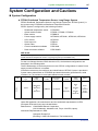
For the Low Voltage directive, EMC directive in EU, the hardware configurations are
described in the following table:
The EU Declaration of Conformity does not cover DTSXL configurations in where Power
supply module NFPW441 is installed.
Information relevant to the conformity and identification of DTSXL System is provided in
System name plate affixed on DTSX3000 and detail information (specifications, serial
numbers, etc.) is provided in name plate affixed on each module.
Normal
Use
Configuration
Type
Power
supply
module *1
Type-N
NFPW426
or
NFPW442
or
NFPW444
Base
module
DTSBM10
Distributed
Temperature
Sensor
DTSX3000
CPU
module
Optical
switch
module
Option
None
or
NFCP050
None
or
DTOS2L
or
DTOS4L
or
DTOS16L
None
or
DTRK10
and/or
DTFB10
*1: Dual-redundant configuration is not allowed for the power supply module.
Under EU legislation, the manufacturer and the authorised representative in EEA
(European Economic Area) are indicated below:
Manufacturer: YOKOGAWA Electric Corporation
(2-9-32 Nakacho, Musashino-shi, Tokyo 180-8750, Japan).
Authorised Representative in EEA:
Yokogawa Europe B.V.
(Euroweg 2, 3825 HD Amersfoort, The Netherlands)
IM 39J06A40-01E
vii
< System Configuration and Cautions >
Installation and Maintenance Notes
SEE ALSO
For more information about installation and maintenamce, refer to DTSXL Distributed Temperature
Sensor Long Range System Guide (IM 39J06B40-01E).
Installation method
Follow the guidance below on how to use this device to guarantee satisfactory safety
and performance.
- Install rack type devices in the metal cabinet.
-
Confirm that all the empty slots are covered by dummy covers.
Confirm that all cables are firmly secured with the screws.
Keep the cabinet door closed and lock the cabinet doors for safety.
Prepare a dedicated circuit breaker in the same room of the device so that it can be
used to cut off the power supply when abnormality occurs. Use this breaker to
shutdown power supply to equipment devices when a device abnormality occurs.
Use a breaker that meets STARDOM power supply specification requirements.
Requirements for Installation
When installing the device, the installation requirements of the device must be satisfied.
Install the device under the following conditions:
*1:
*2:
*3:
Installation height
: Altitude up to 3000 m (*1)
Installation category based on IEC 61010 : I or II (*2)
Pollution degree based on IEC 61010
: 2 (*3)
Altitude up to 2000 m when power supply module NFPW441, NFPW442 or NFPW444 is used.
Installation category is the specification of the impulse withstanding voltage which is termed overvoltage category.
Category I applies to specially protected electrical devices on the secondary side.
Pollution degree represents the level of foreign matter adhesion, solid, liquid, and gaseous, which may decrease the
withstanding voltage.
Pollution degree 2 is applicable to general indoor atmosphere.
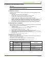
Measurement Categories
Regarding to the measurement inputs, the following requirements must be satisfied to
meet the specifications for the device:
The category of the equipment applies to No.1 in the following table.
The rated transient overvoltage is 1500 V.
Note: Do not use the equipment for measurements within measurement categories II, III and IV.
No.
No.1
Applicable Standard
EC/EN/CSA
61010-1
Measurement category I
EN 61010-2-030
O (Other)
No.2
Measurement category II
Measurement category II
No.3
Measurement category III
Measurement category III
No.4
Measurement category IV
Measurement category IV
Description
For measurements performed on
circuits not directly connected to MAINS.
For measurements performed on
circuits directly connected to the lowvoltage installation.
For measurements performed in the
building installation.
For measurements performed at the
source of the low-voltage installation.
IM 39J06A40-01E
viii
< System Configuration and Cautions >
● Wiring Power Cable
Connect the power cables according to the procedure given in DTSXL Distributed
Temperature Sensor Long Range System Guide (IM 39J06B40-01E).
Power cables must conform to the safety standards of the country where the device is
CAUTION installed.
SEE ALSO
For more information about power cables, refer to DTSXL Distributed Temperature Sensor Long Range
System Guide (IM 39J06B40-01E).
● Earth Wiring
Ground the device following the procedure in DTSXL Distributed Temperature Sensor
Long Range System Guide (IM 39J06B40-01E) to prevent electric shock and to minimize
noise.
CAUTION
SEE ALSO
For more information about earth wiring, refer to DTSXL Distributed Temperature Sensor Long Range
System Guide (IM 39J06B40-01E).
● Battery
CAUTION
• Yokogawa designated batteries must be used.
• Mount and change batteries following the procedure given in DTSXL Distributed
Temperature Sensor Long Range System Guide (IM 39J06B40-01E).
SEE ALSO
For more information about batteries, refer to DTSXL Distributed Temperature Sensor Long Range
System Guide (IM 39J06B40-01E).
IM 39J06A40-01E
ix
< System Configuration and Cautions >
● I/O Devices
To ensure this system compliance with the CSA safety standards, all devices connected
to this system shall be CSA certified devices.
CAUTION
SEE ALSO
For Wiring I/O Cables for I/O Devices, refer to DTSXL Distributed Temperature Sensor Long Range
System Guide (IM 39J06B40-01E).
● Maintenance
CAUTION
• When the device becomes dusty, use a vacuum cleaner or a soft cloth to clean it.
• During maintenance, wear a wrist strap, and adopt appropriate ESD (Electrostatic
Discharge) measures.
SEE ALSO
For Maintenance, refer to DTSXL Distributed Temperature Sensor Long Range System Guide (IM
39J06B40-01E).
● Cards, Cables and Connectors
When power of DTSXL is ON, Do not install or remove the cards, cables, connectors
which are listed in DTSXL Distributed Temperature Sensor Long Range System Guide
(IM 39J06B40-01E).
CAUTION
SEE ALSO
For Cards, Cables and Connectors, refer to DTSXL Distributed Temperature Sensor Long Range
System Guide (IM 39J06B40-01E).
IM 39J06A40-01E
x
< System Configuration and Cautions >
● Laser Beam
Safety Precautions for Laser Products
This instrument uses a laser light source. This instrument is a Class 1M laser product as
defined by IEC60825-1 Safety of Laser Products—Part1: Equipment classification and
requirements. In addition, this instrument complies with 21 CFR 1040.10 except for
deviations pursuant to Laser Notice No. 50, dated June 24, 2007.
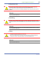
The table below shows the parameters of the laser light used in this instrument.
Table Parameters of Laser Light
Laser Class
Structure
Wavelength
Output power (average)
Pulse train
Pulse time
Pulse repetition cycle
Class 1M
DFB-LD and EDFA
1552 nm
3.8 mW
Periodic pulse train
Max 10 ns
80 µs (min.)
The figure bellow shows Laser Class 1M label. This label is printed on the front panel of
the instrument.
Invisible laser light is output from the OPTICAL OUTPUT terminal located on the front
face of this instrument. When Optical switch module connects to Distributed Temperature
Sensor with the optical fiber, the laser beam is output from optical terminals of Optical
CAUTION switch module.
Do not look directly or indirectly into the laser beam or at a specular reflection of the
beam without protective equipment.
Do not aim the laser beam at the eye. The laser beam may cause blindness or damage
to your eyes. Attach the cover to the optical connector when it is not in use.
Using an optical instrument, such as a loupe, magnifying glass, or microscope, to
observe the laser beam from a distance of less than 100 mm may cause eye injury.
This instrument uses invisible laser light, which may cause eye injury or vision damage if
it enters the human eye. To prevent accidents, always observe the following precautions:
• Do not turn on laser output when no optical fiber is connected to the optical connector.
• Always stop laser output before disconnecting the optical fiber from the optical
connector.
• Never look into the end of an optical fiber connected to the optical connector during
laser output.
High-power laser light may be emitted during disassembly and modification of this
instrument. For this reason, customers must not disassemble or modify this instrument
under any circumstance.
Operating this instrument not in accordance with procedures described in this manual
may result in exposure to hazardous laser emissions.
IM 39J06A40-01E
xi
< System Configuration and Cautions >
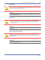
● High Temperature Safety Caution
Figure High Temperature Caution Mark
Avoid skin contact. Burn hazard.
When installed in high ambient temperature environments, the instrument surface may
become hot. Wear thermal protective gloves when touching metallic parts. Avoid direct
CAUTION skin contact. Beware especially in high temperature installation environments.
Measurement
Before performing distributed temperature measurement:
- Ensure that the environment complies with the DTSXL system specifications, and
- Perform temperature calibration of the sensor optical fiber with DTSXL system.
IM 39J06A40-01E
< Copyright and Trademark Notices >
xii
Copyright and Trademark Notices
All Rights Reserved
The copyrights of the programs and online manual contained in the CD-R are reserved.
The online manual is protected by the PDF security from modification, however, it can
be output via a printer. Printing out the online manual is only allowed for the purpose of
using the product. When using the printed information of the online manual, check if the
version is the most recent one by referring to the DVD-ROM’s version.
No part of the online manual may be transferred, sold, distributed (including delivery via
a commercial PC network or the like), or registered or recorded on video tapes.
Trademark and License Software Acknowledgments
•
•
•
•
•
•
•
•
•
DTSX is a registered trademark of Yokogawa Electric Corporation.
STARDOM and CENTUM are trademarks of Yokogawa Electric Corporation.
Ethernet is a registered trademark of Xerox Corporation.
Windows is a registered trademark of Microsoft Corporation in the United States
and other countries.
Modbus is a registered trademark of AEG Schneider.
E2000 is a trademark of Swiss Diamond.
Other company and product names appearing in this document are trademarks or
registered trademarks of their respective holders.
Registered trademarks and trademarks in this document are not displayed with TM
or the ® mark.
The following third-party software is used in the software included in the
accompanying CD-R (or DVD-ROM).
NetAdvantage Icons © 2011 – Infragistics Products
IM 39J06A40-01E
xiii
< User’s Manuals and General Specifications >
User’s Manuals and
General Specifications
List of User’s Manuals and General Specifications for the Product
-
IM 39J06A40-01E:
DTSXL Distributed Temperature Sensor
Long Range System Read Me First
-
IM 39J06B40-01E:
-
IM 39J06B40-02E:
IM 39J06B40-03E:
DTSXL Distributed Temperature Sensor
Long Range System Guide
DTSX3000 Communications(Modbus) Guide
License Agreement for DTSX3000 Software
-
IM 39J06B40-04E:
-
IM 39J06G40-01:
IM 39J06G40-02:
-
IM 39J06G40-03:
IM 39J02B40-01E:
-
IM 39J02B40-02E:
DTSX3000 Terms and Conditions of Open Source
Software
Before using DTSX
Installing Distributed Temperature Sensor
Installing Optical Switch Module for DTSXL
DTAP3000 DTSX3000 Control Visualization Software
Guide
DTAP3000 DTSX3000 Control Visualization Software
-
IM 39J02B40-03E:
-
IM 39J02B40-05E:
Las2.0 Data Conversion Guide
DTAP3000D DTSX3000 Data Conversion Software
WITSML1.3.1.1 Guide
DTAP3000 Installation Manual
-
IM 39J02B40-06:
IM 39J02B40-07E:
IM 39J02B40-08E:
IM 39J02B40-09:
DTAP3000 CHECKING PACKAGE CONTENTS
DTAP3000 Software License Agreement
DTAP3000D Installation Manual
DTAP3000D CHECKING PACKAGE CONTENTS
-
IM 39J02B40-10E:
IM 39J02B40-11E:
-
IM 34P02Q01-01E:
GS 39J06B40-01E:
-
GS 39J02B40-01E:
-
GS 34P02Q12-01E:
GS 34P02Q13-01E:
DTAP3000D Software License Agreement
DTAP3000/DTAP3000D Update Module
Installation Manual
STARDOM FCN/FCJ Guide
DTSXL Distributed Temperature Sensor
Long Range System
DTSXL Distributed Temperature Sensor
Long Range System (Software)
FCN Autonomous Controller Hardware
FCN-RTU Low Power Autonomous Controller Hardware
TIP
These documents can be downloaded on the following URL for online query.
http://www.yokogawa.com/ofs/
IM 39J06A40-01E
< Revision Information >
xiv
Revision Information
Title
: DTSXL Distributed Temperature Sensor Long Range System
Manual No.
: IM 39J06A40-01E
Oct. 2014/1st Edition/
- First published
For Questions and More Information
Online Query: A query form is available on the following URL for online
query.
http://www.yokogawa.com/ofs/
Written by
Yokogawa Electric Corporation
Published by
Yokogawa Electric Corporation
2-9-32 Nakacho, Musashino-shi, Tokyo 180-8750,
Japan
IM 39J06A40-01E