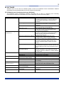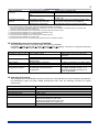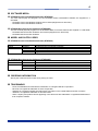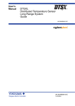
1
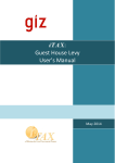
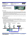
General Specifications GS 39J02B45-01E DTSXM Distributed Temperature Sensor Middle Range System (Software) GENERAL This General Specification (GS) describes the system configuration and software configuration of the DTSXM Distributed Temperature Sensor Middle Range System. FEATURES The DTSXM Distributed Temperature Sensor Middle Range System (DTSXM System) measures temperatures at various points along the length of an optical fiber by launching a pulse of light into a connected optical fiber and analyzing the signal components of the returned backscatter. By using the optical fiber as the intrinsic temperature sensing element, the DTSX200 of DTSXM System is capable of measuring temperature distribution over an area where the optical fiber is laid. As the DTSX200 lacks a man-machine interface, a dedicated DTSX200 Control Visualization Software (DTS200AP) tool is provided to allow a user to perform control, monitoring and analysis via a communication interface. For more details on the DTSXM System, see “DTSXM Distributed Temperature Sensor Middle Range System” (GS 39J06B45-01E). CONFIGURATION System Configuration Up to four control and monitoring stations can be connected to one DTSXM System unit. The DTSX200 of the DTSXM System performs temperature distribution measurement according to instructions from control and monitoring stations and then calculates and accumulates temperature data internally at the end of each profile measurement. A control and monitoring station polls the DTSX200 constantly and when measurement data is available, it retrieves and displays the data. The DTSX200 can also convert data into LAS format or WITSML format (when used with DTAP200D) for transmission to a host data server. DTAP200 (*1, *2) DTAP200D (*1, *2) STARDOM, Web browser (*2) (for DTSX200 (for data CENTUM (*1, *2) (for maintenance) configuration, conversion (for control) control & data configuration & display) operation) Control device SSH, SFTP, SCP SSH, SFTP, SCP Modbus/TCP HTTP Ethernet Modbus Serial (ASCII, RTU) DTSXM RS-232C System Configuration Example (*1) Requires separate purchase; (*2) Neither hardware nor software is included in this specification. Yokogawa Electric Corporation 2-9-32, Nakacho, Musashino-shi, Tokyo, 180-8750 Japan Tel.; 81-422-52-5735 GS 39J02B45-01E © Copyright .2014 3rd Edition Jan. 10, 2014(YK) 2 SOFTWARE Software tools for use with the DTSXM System include the DTSX200 Control Visualization Software (DTAP200) and the DTSX200 Data Conversion Software (DTAP200D). DTSX200 Control Visualization Software (DTAP200) The DTSX200 Control Visualization Software (DTAP200) tool is used for configuring and controlling temperature measurement by DTSX200, as well as displaying measurement data graphs. Item Boot modes Control mode Monitoring mode Trace mode Calibration mode Measurement configuration functions (*1) (Global) measurement settings (Channel) measurement settings (Channel) fiber settings Alarm settings Zone temperature data generation settings DTSX200 control functions Status display functions Alarm display Measurement result display functions Help functions Calibration functions (*5) Communications functions (*3) Connect/Disconnect (*3) Start/Stop measurement (*4) Self-test (*4) Connection status display and measurement status display Notification Detailed information display Graph settings Graph display Version information display and user manual display Calibration of various sensor fiber parameters Communications with DTSX200 All Rights Reserved. Copyright © 2014, Yokogawa Electric Corporation Description The control mode is used for configuring and controlling measurement, as well as displaying measurement results while connected to the DTSX200. The monitoring mode is used for displaying measurement results while connected to the DTSX200. The trace mode is used for displaying trace data without connecting to the DTSX200. The calibration mode is used for tuning temperature measurement parameters while connected to the DTSX200. Settings for channel combination, measurement sequence, measurement mode (single-ended or double-ended), measurement interval and measurement start time Repetition rate, measurement time (*2) or averaging times, distance range, sampling resolution and fiber failure detection threshold Fiber length, wavenumber, group index, loss correction, temperature offset correction and winding coefficient (distance-depth conversion factor) Up to 10 alarm detection zones can be defined with temperature high limit, low limit, rise limit, fall limit and difference limit values specified for each zone. Up to 100 data generation zones can be defined with the temperature output data type (average, maximum, minimum, difference or slope) selected for each zone Authentication using username and password Self-diagnosis by DTSX200 An alarm is indicated by a lit alarm lamp button. Alarm type and alarm location (only for the first occurrence) Data type (temperature, signal level), data unit, graph type (2D or 3D) and display range Displays measurement data. Fiber connection calibration and fiber parameter calibration Uses SSH, SFTP and SCP. GS 39J02B45-01E Jan. 10 2014-00 3 Data management functions LAS data configuration function Get measurement data (*3) Measurement data time series log (*6) CSV output (*7) LAS data conversion configuration and LAS data transmission configuration Saves data to specified folder. Records time series data for a specified depth. Exports specified measurement data in CSV format. (*8) Configuration of LAS (Log ASCII Standard) data conversion (LAS version 2.0 compatible) and data transmission to server by DTSX200 *1: DTSX200 settings can be modified in control mode or calibration mode *2: The measurement time setting refers solely to the measurement duration for averaging. It does not include time for hardware preparation, temperature calculation, alarm detection, zone data creation, file creation, data conversion, data transfer and other auxiliary time. *3: These functions are available only in control mode, monitoring mode and calibration mode. *4: These functions are available only in control mode and calibration mode. *5: These functions are available only in calibration mode. *6: These functions are available only in control mode and monitoring mode. *7: These functions are available only in trace mode. *8: Exported CSV files cannot be re-imported by the DTSX200 Control Visualization Software DTSX200 Data Conversion Software (DTAP200D) The DTAP200D is used for configuring data conversion by DTSX200. If WITSML (Wellsite Information Transfer Standard Markup Language) conversion is configured using this software, the DTSX200 will generate data files in WITSML format. Item DTSX200 control functions Status display functions Alarm display Communications function WITSML data configuration function Specification Connect/Disconnect Start/Stop conversion Connection status display and conversion status display DTSX200 failure notification Communications with DTSX200 WITSML data conversion configuration and WITSML data transmission configuration Remarks Authentication using user name and password An alarm is indicated by a lit alarm button Uses SSH, SFTP and SCP Configuration of WITSML data conversion (WITSML version 1.3.1.1 compatible) and data transmission to server by DTSX200 Operating Environment The DTSX200 Control Visualization Software (DTAP200), DTSX200 Data Conversion Software (DTAP200D), the Maintenance page and other related development tools have the following common PC system requirements. Item Personal computer CPU RAM Hard disk free space Ethernet adaptor OS .NET framework Web browser Specification IBM PC/AT compatible Dual-core 32-bit processor 2 GHz or better 2 GB or more 2 GB or more 100BASE-TX or 10BASE-T Windows7 Home Premium SP1(x86 / x64) Windows7 Ultimate SP1 (x86 / x64) Windows7 Professional SP1 (x86 / x64) Windows7 Enterprise SP1 (x86 / x64) .NET framework 4 Internet Explorer 8 All Rights Reserved. Copyright © 2014, Yokogawa Electric Corporation GS 39J02B45-01E Jan. 10 2014-00 4 SOFTWARE MEDIA DTSX200 Control Visualization Software (DTAP200) The user manual (IM) and programs for the DTSX200 Control Visualization Software are supplied on a CD-ROM. - DTSX200 Control Visualization Software user manual (IM) (Electronic document) - DTSX200 Control Visualization Software DTSX200 Data Conversion Software (DTAP200D) The user manual (IM) and programs for the DTSX200 Data Conversion Software are supplied on a CD-ROM. - DTSX200 Data Conversion Software user manual (IM) (Electronic document) - DTSX200 Data Conversion Software MODEL AND SUFFIX CODES DTSX200 Control Visualization Software (DTAP200) Model Suffix Codes DTAP200 -N 0 E Description DTSX200 Control Visualization Software Standard license (Runtime license for one PC) Basic type English DTSX200 Data Conversion Software (DTAP200D) Model Suffix Codes DTAP200D -N 1 E Description DTSX200 Data Conversion Software Standard license (Runtime license for one DTSX200) WITSML1.3.1.1 English ORDERING INFORMATION Specify the model and suffix codes when placing an order. TRADEMARKS - DTSX, STARDOM and CUNTUM are trademarks of Yokogawa Electric Corporation. Ethernet is a registered trademark of Xerox Corporation. Windows is a registered trademark of Microsoft Corporation in the United States and other countries. Modbus is a registered trademark of AEG Schneider. Other company and product names appearing in this document are trademarks or registered trademarks of their respective holders. All Rights Reserved. Copyright © 2014, Yokogawa Electric Corporation GS 39J02B45-01E Jan. 10 2014-00