1
User's
Manual
ProSafe-RS Release Information
IM 32Q01A50-31E
IM 32Q01A50-31E
4th Edition
i
Introduction
This brochure is the release note that comes with the ProSafe-RS electronic documents. It
provides supplementary information not included in the ProSafe-RS electronic documents.
The structure of this document is shown below.
Chapter 1 : Usage Notes for Revision R3.02.20
This chapter explains the points to be noted when applying revision R3.02.20.
Media No. IM 32Q01A50-31E (CD)
4th Edition : Jan. 2015 (YK)
All Rights Reserved Copyright © 2011 , Yokogawa Electric Corporation
IM 32Q01A50-31E
4th Edition : Jan.30,2015-00
ii
Safety Precautions for Use
n Safety, Protection, and Modification of the Product
•
To protect the system controlled by the Product and the Product itself and to ensure safe
operation, please observe the safety precautions described in this Manual. Yokogawa
Electric Corporation ("YOKOGAWA") assumes no liability for safety if users fail to observe
the safety precautions and instructions when operating the Product.
•
If the Product is used in a manner not specified in the User's Manuals, the protection provided by the Product may be impaired.
•
If any protection or safety circuit is required for the system controlled by the Product or for
the Product itself, please install it externally.
•
Use only spare parts that are approved by YOKOGAWA when replacing parts or consumables of the Product.
•
Do not use the Product and its accessories such as power cords on devices that are not
approved by YOKOGAWA. Do not use the Product and its accessories for any purpose
other than those intended by YOKOGAWA.
•
Modification of the Product is strictly prohibited.
•
The following symbols are used in the Product and User's Manuals to indicate the accompanying safety precautions:
Indicates that caution is required for operation. This symbol is labeled on the Product to refer the user to the User's Manuals for necessary actions or behaviors in
order to protect the operator and the equipment against dangers such as electric
shock. In the User's Manuals, you will find the precautions necessary to prevent
physical injury or death, which may be caused by accidents, such as electric
shock resulting from operational mistakes.
Identifies a protective conductor terminal. Before using the Product, you must
ground the protective conductor terminal to avoid electric shock.
Identifies a functional grounding terminal. A terminal marked "FG" also has the
same function. This terminal is used for grounding other than protective grounding.
Before using the Product, you must ground this terminal.
Indicates an AC supply.
Indicates a DC supply.
Indicates the ON position of a power on/off switch.
Indicates the OFF position of a power on/off switch.
n Notes on Handling User's Manuals
•
Hand over the User's Manuals to your end users so that they can keep the User's Manuals on hand for convenient reference.
•
Thoroughly read and understand the information in the User's Manuals before using the
Product.
•
For the avoidance of doubt, the purpose of the User's Manuals is not to warrant that the
Product is suitable for any particular purpose but to describe the functional details of the
Product.
•
Contents of the User's Manuals are subject to change without notice.
IM 32Q01A50-31E
4th Edition : Jan.30,2015-00
iii
•
Every effort has been made to ensure the accuracy of contents in the User's Manuals.
However, should you have any questions or find any errors, contact us or your local distributor. The User's Manuals with unordered or missing pages will be replaced.
n Warning and Disclaimer
•
Except as specified in the warranty terms, YOKOGAWA shall not provide any warranty for
the Product.
•
YOKOGAWA shall not be liable for any indirect or consequential loss incurred by either
using or not being able to use the Product.
n Notes on Software
•
YOKOGAWA makes no warranties, either expressed or implied, with respect to the Software Product's merchantability or suitability for any particular purpose, except as specified in the warranty terms.
•
Purchase the appropriate number of licenses of the Software Product according to the
number of computers to be used.
•
No copy of the Software Product may be made for any purpose other than backup; otherwise, it is deemed as an infringement of YOKOGAWA's Intellectual Property rights.
•
Keep the software medium of the Software Product in a safe place.
•
No reverse engineering, reverse compiling, reverse assembling, or converting the Software Product to human-readable format may be performed for the Software Product.
•
No part of the Software Product may be transferred, converted, or sublet for use by any
third-party, without prior written consent from YOKOGAWA.
n Notes on Hardware
l
Appearance and Accessories
Check the following items when you receive the Product:
•
Appearance
•
Standard accessories
Contact us or your local distributor in the following cases:
•
The Product coating is peeling off.
•
The Product itself is damaged.
•
Any accessories are missing.
If the following label turns dirty and the information on it becomes illegible, or if the label is
peeling off, order a new one with the part number T9029BX to replace it.
: Label attached to the Products such as the power supply module.
l
Model and Suffix Codes
The name plate on the Product contains the model and suffix codes. Verify the model and suffix codes with those in the General Specifications (GS) to ensure that the Product matches
the order specifications. Should you have any questions, contact us or your local distributor.
IM 32Q01A50-31E
4th Edition : Jan.30,2015-00
iv
Documentation Conventions
n Symbols
The following symbols are used in the User's Manuals.
Identifies instructions that must be observed to avoid physical
injury, electric shock, or death.
Identifies instructions that must be observed to prevent damage
to the software or hardware, or system failures of the Product.
Identifies important information required to understand operations or functions.
Identifies additional information.
Identifies referenced content.
In online manuals, you can view the referenced content by clicking the links that are in green text. However, this action does not
apply to the links that are in black text.
n Typographical Conventions
The following typographical conventions are used throughout the User's Manuals.
Commonly Used Conventions throughout the User's Manuals
l
•
Δ Mark
Indicates that a space must be entered between character strings.
Example:
.ALΔPIC010Δ-SC
•
Character string enclosed by braces { }
Indicates character strings that may be omitted.
Example:
.PRΔTAG{Δ.sheet name}
Conventions Used to Show Key or Button Operations
l
•
Characters enclosed by brackets [ ]
When characters are enclosed by brackets in the description of a key or button operation,
it indicates a key on the keyboard, a button name in a window, or an item in a list box
displayed in a window.
Example:
To alter the function, press the [ESC] key.
Conventions of a User-defined Folder
l
•
User-defined folder name enclosed by parenthesis ( )
User definable path is written in a pair of parentheses.
Example:
IM 32Q01A50-31E
4th Edition : Jan.30,2015-00
v
(RS Project Folder)\SCS0101
If the RS Project Folder is C:\MYRSPJT, the above path becomes C:
\MYRSPJTSCS0101.
n Drawing Conventions
Drawings used in the User's Manuals may be partially emphasized, simplified, or omitted for
the convenience of description.
Drawings of windows may be slightly different from the actual screenshots with different settings or fonts. The difference does not hamper the understanding of basic functionalities and
operation and monitoring tasks.
n Integration with CENTUM
The Product can be integrated with CENTUM VP or CENTUM CS 3000. In the User's Manuals, the integration with CENTUM VP or CENTUM CS 3000 is referred to as "Integration with
CENTUM."
In the User's Manuals, the explanations for integrating the Product with CENTUM VP or
CENTUM CS 3000, the glossary for various features of CENTUM VP is used instead of the
glossary for CENTUM CS 3000. For example, the term "CENTUM VP System Alarm View" is
used instead of "CENTUM CS 3000 System Alarm window." Nevertheless, if the features for
integrating the Product with CENTUM VP and CENTUM CS 3000 are different, both features
will be explained separately.
SEE
ALSO
For more information about the functions and usage of CENTUM VP components for integrating the Product
with CENTUM VP, refer to:
User's Manuals (IM), Technical Information (TI), and General Specifications (GS) of CENTUM VP
For more information about the features and usage of CENTUM CS 3000 components for integrating the
Product with CENTUM CS 3000, refer to:
User's Manuals (IM), Technical Information (TI), and General Specifications (GS) of CENTUM CS 3000
n Explanation of Hardware and Software Behaviors in the User's
Manuals
In the User's Manuals, system behaviors are explained assuming that the latest versions of
YOKOGAWA software and hardware at the time of publication of the User's Manuals are installed.
If additional precise information about the safety of legacy versions of software or hardware is
required, a link to the corresponding explanation is provided. Please refer to the information
according to your system.
n Station Types
A safety control station (hereafter referred to as SCS) is named according to the type of the
safety control unit used in it.
Table Info-1 Names of SCS and Safety Control Unit Used
Name of SCS
Model of the safety control unit
SCSV1-S
SSC10S/SSC10D
SCSP1-S
SSC50S/SSC50D
SCSP2-S
SSC60S/SSC60D
SCSU1-S
SSC57S/SSC57D
IM 32Q01A50-31E
4th Edition : Jan.30,2015-00
vi
In the User's Manuals, the following abbreviations may be used to describe functions of these
SCS as a whole.
•
SCSV1: Abbreviation of SCSV1-S
•
SCSP1: Abbreviation of SCSP1-S
•
SCSP2: Abbreviation of SCSP2-S
•
SCSU1: Abbreviation of SCSU1-S
IM 32Q01A50-31E
4th Edition : Jan.30,2015-00
vii
Copyright and Trademark Notices
n All Rights Reserved
The copyright of the programs and online manuals contained in the software medium of the
Software Product shall remain with YOKOGAWA.
You are allowed to print the required pages of the online manuals for the purposes of using or
operating the Product; however, reprinting or reproducing the entire document is strictly prohibited by the Copyright Law.
Except as stated above, no part of the online manuals may be reproduced, transferred, sold,
or distributed to a third party in any manner (either in electronic or written form including, without limitation, in the forms of paper documents, electronic media, and transmission via the
network). Nor it may be registered or recorded in the media such as films without permission.
n Trademark Acknowledgments
•
CENTUM, ProSafe, Vnet/IP, and STARDOM are registered trademarks of YOKOGAWA.
•
Microsoft, Windows, Windows Vista, Windows Server, Visual Basic, Visual C++, and Visual Studio are either registered trademarks or trademarks of Microsoft Corporation in the
United States and other countries.
•
Adobe, Acrobat, and Adobe Reader are registered trademarks of Adobe Systems Incorporated.
•
Ethernet is a registered trademark of Xerox Corporation.
•
HART is a registered trademark of the HART Communication Foundation.
•
Modicon and Modbus are registered trademarks of Schneider Electric SA.
•
All other company and product names mentioned in the User's Manuals are trademarks
or registered trademarks of their respective companies.
•
TM or ® mark are not used to indicate trademarks or registered trademarks in the User's
Manuals.
•
Logos and logo marks are not used in the User's Manuals.
IM 32Q01A50-31E
4th Edition : Jan.30,2015-00
Toc-1
ProSafe-RS Release Information
IM 32Q01A50-31E 4th Edition
CONTENTS
1.
Usage Notes for Revision R3.02.20.................................................... 1-1
1.1
Safety Control Stations................................................................................ 1-2
1.2
Engineering................................................................................................... 1-8
1.3
SCS Maintenance Support Tool................................................................ 1-16
1.4
Integration with CENTUM...........................................................................1-17
1.5
SOE (Sequence of Events).........................................................................1-18
1.6
Access Control and Operation History Management Package.............. 1-19
1.7
Miscellaneous............................................................................................. 1-20
IM 32Q01A50-31E
4th Edition : Jan.30,2015-00
<1. Usage Notes for Revision R3.02.20>
1.
1-1
Usage Notes for Revision R3.02.20
This chapter explains the points to be noted when applying the revision number R3.02.20 of
ProSafe-RS.
SEE
ALSO
For more information about operation of Workbench, refer to:
Workbench User's Guide
IM 32Q01A50-31E
4th Edition : Jan.30,2015-00
1-2
<1.1 Safety Control Stations >
1.1
Safety Control Stations
This section describes the notice for using the safety control stations.
n Behavior of SDV526 (100-120 VAC DO Module) in Dual-Redundant
Configuration
If the standby-side SDV526 module recovers (for example, after it is replaced) while the application logic is outputting an ON signal to the dual-redundant SDV526 modules and the signal
from the application logic changes to OFF immediately (within two seconds) after the recovery, it takes a maximum of two seconds until the signal output to the field changes from ON to
OFF.
n Cautions on Input Signals of DI Modules
The DI module has a software filter for filtering the input signals. The chattering signals from
the field are filtered out so as to prevent the incorrect actions. Principally, only the signals
elapse longer than the filter setting should be input from the DI module.
When the transient signal with the pulse shorter than the filter setting value (such as a chattering signal) repeats and prolongs, this phenomenon can be taken as a channel failure.
When the DI modules are in dual-redundant configuration, either controlling-side or standbyside of the DI module may fail as a channel failure.
If an error occurs in a channel but no abnormality is found in field cables and I/O modules, it is
necessary to check whether the signal itself is correct or not.
n Cautions on Replacing SAI143 (AI Module)
When replacing dual-redundantly configured AI modules (SAI143) during maintenance, the 2wire/4-wire pin-set on SAI143 should be properly positioned according to the actual setting on
the active module. If the settings on the two modules are different, both modules may fail.
n Lock Status at Online Change of I/O Modules
Locking of I/O modules will be cancelled when the following changes are made by online
change download.
•
The model of I/O modules are changed.
•
I/O modules are deleted.
•
Device index is changed due to the following definition change (*1)
• Deletion-and-addition of I/O modules
•
*1:
*2:
•
Two single I/O modules are change into dual-redundant configuration.
•
Dual-redundant I/O modules are changed into two single modules.
The installation position or single/dual-redundant specification of subsystem communication modules are changed. (*2)
Whether or not a locked I/O module stays locked after online change download is based on Device index. A locked module
will stay locked if its model and Device index remain the same after the deletion-and-addition, even if the node number or slot
number is changed.
If a serial communication module that is defined to be single configuration and installed in an even-numbered slot is changed
to dual-redundant configuration starting with an odd-numbered slot, it is regarded as "change in installation position."
n Deleting-and-Adding an I/O Module
In the case, for example, where an I/O module is deleted by mistake on I/O Wiring View and a
module definition is added for recovery, the Device index may be changed. If online change
IM 32Q01A50-31E
4th Edition : Jan.30,2015-00
1-3
<1.1 Safety Control Stations >
download is performed with a changed Device index, the locking and the inputs/outputs of the
module are discontinued, even if its model, node number, and slot number are unchanged. To
continue the I/O module operation, set the Device index back to the value before deletion and
then perform online change download.
SEE
ALSO
For more information about the behavior when online change download is performed with changed Device
indexes, refer to:
“● Online Change of Single/Dual-redundant Specification of AIO/DIO Modules” in “■ Cautionary Items for
Online Change Operation” in 5.3, “Precautions for Online Change” of the Engineering Guide (IM
32Q01C10-31E)
n Values under Forcing when Single/Dual-redundant Specification of
the AIO/DIO Module is Changed
When the single/dual-redundant configuration definition of an AIO/DIO module is changed by
online change download, IOM download takes place and the target AIO/DIO module is stopped and initialized. Therefore, the module's values under forcing will be initialized even if the
module is locked (the input values start from the values input from the field and the output
values start from the "default initial value upon power-on")
n Adding Communication Modules by Online Change Download
In a single online change download operation, you cannot add modules for different communication functions together. This limitation comes from the inability to simultaneously download
different types of communication programs to SCS, which is attempted when you try to add
modules for different types of communication in a single online change download.
If you try to add two or more types of communication modules online, the following error may
occur.
No. 0477: Error in database download to I/O module
Example:
SCS0101 IOM Download Error FIO NODE 01 SLOT 01 Error=A731
A731: Simultaneous downloading of different types of communication programs was a
ttempted.
Workaround:
Ensure to add communication modules for only one type of communication in a single online
change download.
The following table shows the types of communication and the corresponding communication
modules.
Table 1.1-1 Types of communication and communication modules
Type of communication
Subsystem communication
Modbus communication
Communication module to use
ALR111, ALR121
ProSafe-SLS communi- ALR121
cation
Modbus slave communication
DNP3 communication
Serial
ALR111, ALR121
Ethernet
ALE111
ALE111
IM 32Q01A50-31E
4th Edition : Jan.30,2015-00
1-4
<1.1 Safety Control Stations >
For example, you must add only ALR111 or ALR121, which is for Modbus slave communication, in a single online change download.
Restoration:
From the SCS State Management window, run IOM download for the communication module
that caused the download error.
n Online Change Download of SCS Constants Builder Definitions
Do not download changes in the SCS Constants Builder definitions and other changes together in a single online change download operation. You need to download changes in SCS Constants Builder definitions first and then download other changes such as those made to the
application logic. If you download them at the same time by online change download, the behavior of the SCS will be as follows because the SCS processes the changes in application
logic first.
Example 1:
If you change the setting of [Behavior at Abnormal Calculation] from [SCS fails] to [SCS continues] and also make changes and additions to the application logic and download all the
changes together by online change download, the SCS will stop if any abnormal calculation
occurs in the added of modified application logic.
Example 2:
If you change the setting of [Extend Scan Period Automatically] from [No] to [Yes] and also
make changes and additions to the application logic and download all the changes together
by online change download, the automatic scan period extension function will not work during
the downloading. This means that the online change download may not be completed if the
execution time of the application logic exceeds the scan period of the application logic execution functions as a result of adding a large amount of application logic.
n Configuration Errors Immediately after Offline Download
Even if the IOM download is performed normally during offline download, the I/O module
whose front connector is left open may cause a configuration error while the SCS starts up
after the offline download.
If such a configuration error occurred, plug the connector cable to the front connector of the
I/O module and if necessary, supply power to the module from an external power source.
If the configuration error still remains after plugging in the front connector, there is a possibility
that the IOM download to the I/O module had failed. In this case, use the [IOM Load] command on the SCS State Management window to execute IOM download manually.
n Execution of Automatic IOM Download
If you have replaced the standby-side module of dual-redundant I/O modules while the CPU
of the SCS is stopped, IOM download does not take place automatically when you start up
the SCS. (*1)
In this case, use the [IOM Load] command on the SCS State Management window to execute IOM download manually or retry automatic IOM download by doing one of the following
operations:
•
Pull out the I/O module and insert it again.
•
Turn off the power to the node where the I/O module is installed and turn it on again.
•
Disconnect the ESB bus line of the node where the I/O module is installed and connect
it again.
*1:
Automatic IOM download does not take place if a configuration error of I/O module has occurred when the CPU modules of
the SCS start up.
IM 32Q01A50-31E
4th Edition : Jan.30,2015-00
1-5
<1.1 Safety Control Stations >
n Breakpoint Usage in Target Tests
When using breakpoints on SCS Manager during target tests, the CPU module of the SCS
should be in single configuration. With dual-redundant CPU modules, the following phenomena may occur.
Control Right Switching
l
When the CPU modules are in dual-redundant configuration and execution of the application
logic is stopped at a breakpoint, the control-side CPU module may fail and therefore control
right switching is caused. This tends to occur when the scan period of the application logic
execution function is short (for example, 50 ms). When the scan period is 100 ms or longer,
this phenomenon does not occur unless tag data are referenced from CENTUM HIS or other
system.
Workaround:
There is no workaround for this problem.
Restoration:
If the control-side CPU module fails, it automatically restarts once. If the CPU module does
not restart, restart it manually.
APC Does Not End
l
If the execution of the application logic is stopped at a breakpoint while APC is running, the
APC may not be completed. However, this rarely happens. It should also be noted that APC
may not be completed if it is started while the application logic is stopped at a breakpoint. In
these cases, the APC does not end even if you delete the breakpoints.
Workaround:
There is no workaround for this problem. Use breakpoints after APC is completed.
Restoration:
Delete the breakpoints, and then restart the standby-side CPU module so that APC runs
again.
n Messages Output upon Control Right Switching of Dual-redundant
CPU Modules: SCSP2
In SCSP2, if a control right switching of the CPU module occurs during failure of one of the
power supply modules of an I/O node or failure of one of the back board buses (SB bus) of
any I/O module, the following diagnostic information messages may be generated.
•
Recovery (No. 0068) and failure (No. 0067) of a power supply module of a node
•
Recovery (No. 0086) and occurrence (No. 0085) of a communication error in an I/O module
Also note that, if a control right switching of the CPU module occurs when one of the ESB
buses connected to a node has failed and an I/O module is pulled out, the following diagnostic information message may be generated for the module that is pulled out.
•
I/O module database error occurred (No. 0083)
Workaround:
There is no workaround for this problem.
Restoration:
You do not need to take action because only the diagnostic information messages are generated.
IM 32Q01A50-31E
4th Edition : Jan.30,2015-00
1-6
<1.1 Safety Control Stations >
n Messages Output when Standby-side CPU Module is Inserted:
SCSP2
When a stand by-side CPU module (SCP461) is inserted while the SSC60D-F (Duplexed
Safety Control Unit (for Vnet/IP, Wide Range Temperature Type)) is running with a single CPU
module, the following diagnostic information messages may be generated:
•
Safety control station fan alarm (No. 0041)
•
Recovery from safety control station fan alarm (No. 0042)
If the recovery message is generated, you do not need to take action.
n Behavior at Start Up of an SCS: SCSP2
When an SCSP2 starts up, a diagnostic information message indicating module failure (No.
0081 Code = C580) is generated for each ALR111/ALR121/ALE111 defined for Modbus slave
communication and then a recovery message is generated (No. 0082) for each of the modules.
Workaround:
There is no workaround for this problem.
Restoration:
You do not need to take action because the SCS recovers from the error by itself.
n Note on the Use of Communication Module for Modbus Slave
Communication: SCSP2
If any ALR111/ALR121/ALE111 is used for Modbus slave communication in SCSP2, the scan
period for application logic execution functions should be set to 100 ms or longer.
Setting a scan period shorter than 100 ms may result in an error in Modbus slave communication.
n Replacement of CPU Module in Stand-alone SCS Configuration
When you replace one of the dual-redundant CPU module of the SCS that is running in standalone SCS configuration, a diagnostic information message informing "GPS interface unit error" (No. 4129) may be generated regardless of whether GPS is used or not. However, you do
not need to take any action because the SCS is normal even if this message appears. A recovery message (No. 4130) is generated after the replacement of the CPU module is finished.
n Notice on Supplying Power to One of a Pair of Power Modules of a
Node
In the case, for example, when an SCS is configured to be powered by dual-line power supply, if power to the paired power modules in the SCS or its node is turned on one by one, the
digital input or output modules (SDV144, SDV521, SDV531, and SDV541) may fail to start.
This phenomenon occurs very rarely.
Under this situation, you will find the message "IOM model Code Error (0x0000 5102)" on the
IOM Report of SCS Maintenance Support Tool.
This phenomenon may occur when power is supplied one by one for each side of the paired
power modules in an SCS where a node is installed with more than three analog input or output modules (SAI143, SAV144, or SAI533).
Nevertheless, it does not mean that the I/O modules are abnormal.
IM 32Q01A50-31E
4th Edition : Jan.30,2015-00
1-7
<1.1 Safety Control Stations >
Avoidance:
Turn on the power to both of the dual-redundant power modules at the same time.
Restoration:
If the digital input or output modules in a node fail to start when power is turned on one by one
for the power modules, and "IOM model Code Error(0x0000 5102)" is indicated in the IOM
Report, turn on the power supplies again before enabling the output of the SCS (before executing the Output Enable operation).
n Behavior at event acquisition request on DNP3 slave function:
SCSU1
When DNP3 master sends an event acquisition request by specifying a quantity and then
multiple response frames from the SCS are returned, the SCS may sends more than the
specified quantity of events. The total quantity of events that the SCS sends is the quantity of
all specified classes or all specified data-type events that are stored in the SCS event buffer.
This phenomenon happens when Multi fragments are selected as “Type of response message fragmentation” and multiple response frames are returned. When Single fragment is selected, the SCS behaves according to the specification. (The SCS returns events that can be
stored in the maximum size frame as a response.)
If there is a possibility that multiple response frames to the event acquisition request where a
quantity is specified are returned, select Single fragment. Number of events that can be stored in one response frame is as follows:
•
32bit Analog Input with timestamp: 132
•
Binary Input with timestamp: 198
Workaround:
There is no workaround for this problem.
IM 32Q01A50-31E
4th Edition : Jan.30,2015-00
1-8
<1.2 Engineering >
1.2
Engineering
In this section the cautions regarding engineering work are explained.
n Project Comparing Tool
Differences between POUs
l
If there are POUs that are written in FBD and have no differences except comments for variables indicated in a diagram and Short Name (a name representing a parameter) for user-defined FU/FB, difference detection between them concludes as no modifications, which results
in being unable to show or print details.
However, the above differences will be marked if POUs have differences other than the
above.
Restoration:
Confirm whether comments for variables or Short Name are different when you perform difference detection in a variable overview or a parameter overview.
Comparing with an Imported Project
l
When you try to compare a project (hereinafter referred as Project 1) with another project
(hereinafter referred as Project 2) which has been newly created and the entire contents of
Project 1 has been imported, differences may be detected in the following data at the event of
comparison by means of a project comparing tool.
•
DefinedWord
•
GlobalVariables
•
DetailedBinding
•
LocalVarsAndParams (local variables and parameters)
•
ResourceContent (POU overview)
When you import to regenerate a project, ensure that the above data with detected differences has no differences by means of Cross Reference Analyzer. Cross Reference Analyzer is
capable of finding no differences correctly.
Workaround:
There is no workaround to compare Project 1 and Project 2 directly by means of project comparing tool.
To verify the differences from the original project data by using the project comparing tool after
you modify the imported data, you need to save and keep either of the following data as a
reference of comparison.
•
Copy of the project 2 immediately after the import.
•
Master project which is generated by offline downloading immediately after the import.
Compare either of the above projects to the one you have modified by means of project comparing tool.
Restoration:
There is no workaround for this problem.
IM 32Q01A50-31E
4th Edition : Jan.30,2015-00
1-9
<1.2 Engineering >
n Online Change Download
Online Change the Definition of Bindings for the Inter-SCS Safety
Communication
l
The definition of bindings for the inter-SCS safety communication cannot be changed online.
If a definition of binding is added or deleted, a warning message will be displayed when running build. And the online change downloading will end with an error.
However, under the following circumstance, no warning message will be displayed and the
online change downloading can be performed successfully though the changed bindings are
not properly functioning for the inter-SCS safety communications. So, the operations below
must be avoided before performing online change downloading:
•
Moves a consuming side binding variable to a different binding group on the consuming
side.
•
Moves or copies a producing side binding variable to a different binding group on the producing side.
Restoration:
If the above changes were performed, offline downloading should be performed instead of online change downloading.
n Online Monitoring
Online Monitoring after Upgrading SENG
l
After upgrading SENG to R1.01.30 or a later revision and running build, when starting Debug
Mode without downloading to SCS (either online or offline), the following error messages will
occur for online monitoring:
FI20861.LTRP: Adding variable for spy has failed! No symbol table for debug found
!
FI20861.OUT: Adding variable for spy has failed! No symbol table for debug found!
Workaround/Restoration:
After upgrading SENG to R1.01.30 or a later revision and running build, it is necessary to perform downloading to SCS (either online or offline) before starting Debug Mode.
Windows for Online Monitoring
l
When performing online monitoring, do not use window other than those below:
l
•
I/O Lock Window
•
Multi-Language Editor
•
Dictionary
•
Spy List Window
Generate Debug Information
After offline downloading, if the [Generate debug information] of a POU is changed from OFF
to ON and then online downloaded, the "Call stack is in overflow" error dialog box may be displayed twice for each step when the Workbench is in Debug mode and running the step debugging.
Workaround:
If you change the setting of [Generate debug information], perform offline downloading. If you
are executing the SCS Simulator, you should restart it.
IM 32Q01A50-31E
4th Edition : Jan.30,2015-00
<1.2 Engineering >
1-10
Restoration:
Perform offline downloading. If you are executing the SCS Simulator, you should restart it.
Online Monitoring FBD
l
At first, you use Multi-Language Editor to open an FBD and change a function block into a
function or an operator. Then save the modified contents only once, build and download the
FBD. When you execute online monitoring of the FBD, the output of the modified function or
operator may be indicated with "???."
Workaround:
After changing a function block into a function or an operator, the modified contents need to
be saved twice. And then build and download.
The same phenomenon of "???" indication also occurs in Logic Simulator and SCS Simulator.
Therefore, it is necessary to confirm on the Logic Simulator and SCS Simulator that the "???"
indication is not existing, and then start downloading.
Restoration:
Open the FBD that calls the erroneous function or operator, and then save the FBD and build.
And then perform online download the FBD.
Drag and Drop on Link Architecture View
l
On Link Architecture View, when you change a user-defined function block into a user-defined
function with drag and drop operation, and then build and offline download without opening
and saving the POUs that call the modified user-defined function, the output of the modified
user-defined function will be displayed "???" at monitoring.
Workaround:
Before build and offline download, the POUs that call the dragged and dropped function need
to be saved. And then run build and offline download.
The same phenomenon of "???" indication also occurs in Logic Simulator and SCS Simulator.
Therefore, it is necessary to confirm on the Logic Simulator and SCS Simulator that the "???"
indication is not existing, and then start downloading.
Restoration:
Open the POUs that call the erroneous function, and then save and build the POUs and then
perform online download of the POUs.
n I/O Lock Window
Online Change Download
l
If you perform an Online change download, close the I/O Lock Window.
n Workbench
POU Name
l
The POU names (including FU/FB, user-defined FU/FB, libraries registered FU/FB and program) should be unique to each other.
Interruption from Keyboard during Data Transmission
l
Do not perform unnecessary keyboard operation during data transmission such as saving data to the hard disk or sending data to SCS by Workbench.
Do not type any key on the keyboard especially during the following operations:
•
Build
•
Offline Download
IM 32Q01A50-31E
4th Edition : Jan.30,2015-00
<1.2 Engineering >
•
Master Database Offline Download
•
Online Change Download
•
IOM Download
•
Restore Master Database
•
Version Control Check-In/Check-Out
1-11
Display in Dictionary View
l
When you are using Dictionary View in Debug/Simulation mode while [Locked variables] or
[Unlocked variables] is selected for filtering, the display in the Dictionary View will be as follows if you change the variable group or variable scope on the tree shown in the left pane.
•
Filtering is disabled and all the variables that belong to the selected variable group or
scope are displayed regardless of whether the variables are locked or not.
•
The filter status indicated in the upper right of the window remains unchanged even after
the filter is disabled.
Workaround:
There is no workaround for this problem. You can find out whether the variables are locked or
not by the yes (locked) or no (not locked) indication in the [Locked] column of the Dictionary
View.
Restoration:
After you have changed the variable group or variable scope, always select [All variables] to
cancel the filtering and then re-select the filter ([Locked variables] or [Unlocked variables]) you
want to use.
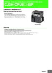
l
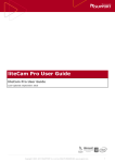
Use of LD Element OR in FBD
If the LD element, OR(LD Vertical OR Connection) is used in FBD, incorrect database which
does not behave as expected may be generated.
b01
b02
b04
b07
b03
b05
b06
LD Vertical OR Connection
Figure 1.2-1 Error example
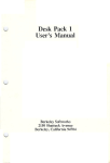
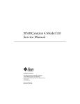
Workaround/Restoration:
Use the OR operator instead of the LD Vertical OR Connection.
OR
b01
b02
OR
b04
b07
b03
b05
b06
OR Operator
Figure 1.2-2 Correction
IM 32Q01A50-31E
4th Edition : Jan.30,2015-00
<1.2 Engineering >
l
1-12
Character-string Constant
If you want a '$' to be denoted in a character-string constant, it should be '$$' according to the
rule. But if a character-string constant ends with a '$', a Build error is raised.
If you need to end a character-string constant with '$$' to denote '$', use '$24' for the '$$'.
n Error Messages Displayed on Workbench
The operation messages displayed on Workbench are explained below.
l
Build a Project without POU
When building a project without POU for the second time, the following error message will be
displayed.
ERROR: GetFileAttributesEx (File Path)\Symbols_Target.xtc.
ERROR: CRHESymAccess::Load error 0x2.
Generation was aborted.
Workaround:
Create a POU before build the project.
Restoration:
Choose [Clean Project] from [Project] menu of Workbench, then the error message will not be
displayed.
l
Build
Suppose, an FB (referred to as FB-B) and another FB (referred to as FB-A) that uses the FBB as parameters exist.
If the FB-B is deleted from the POU tree on the Resource window (it also means that the FBB no longer exists), but the parameters used on FB-A are not deleted, the following message
will occur when running build:
Error: A Type of variable is empty.
Under this circumstance, the FB-B parameters (including instances) used in FB-A should all
be deleted and then run build again.
Workaround/Restoration:
Check the FB hierarchies so as to understand their relationship and then delete the FB properly.
l
Initializing Arrayed Variables in ST
If initial value is set to only part of elements in an array with local variables in FU, the following
build error is raised. Specify an initial value to all the elements in the array.
Err 0059-0000:(2):,:unexpected statement
l
Online Change Download Error
If you exit the Debug mode while Workbench is running and try to execute online change
download, the online change download may fail with the following error message.
ERROR:On-line change download is not executed under Debug or Simulation mode.
This error occurs if you start the Debug mode on Multi-Language Editor and immediately (before data monitoring starts on Multi-Language Editor) exit the Debug mode from Workbench.
Workaround:
IM 32Q01A50-31E
4th Edition : Jan.30,2015-00
1-13
<1.2 Engineering >
After you start the Debug mode, do not exit the Debug mode until the data monitoring display
starts.
Restoration:
Exit Workbench and start it again.
n Cross Reference Analyzer
REAL Type Constant in POU
l
If a REAL type constant is used in a POU, there will be a discrepancy between R2.01 and
previous versions databases. However, this discrepancy will be indicated in green on Cross
Reference Analyzer. There is no need to test it again.
However, if REAL type constant is used in an expression with (=) or (<>) comparator, the true
or false result may be different from the expected result.
If accurate comparison operation (=, <>) on REAL type is detected, Integrity Analyzer displays
a warning. In this case, you need to check the expression and make sure if the program
needs to be enhanced using "smaller than (<)" or "greater than (>)." If the expression in the
POU is correct and there is no need to modify the program, you can ignore the warning message on Integrity Analyzer and you can download it to SCS.
"Instruction modified" Notification
l
According to the technical specification, from R1.01.30, upon the following operations, the
Cross Reference Analyzer will display the “Instruction modified” notification. Thus, the POU
should be tested.
•
When upgrading SENG from R1.01.00/R1.01.10 to R1.01.30 or a later revision, the "Instruction modified" will be notified for the user-defined FU that contains local variables.
•
If you switch the setting of [Generate debug information] (*1) of a POU described in LD
or ST, the message "Instruction modified" will be notified to all the POUs containing a
user-defined FU or a user-defined FB.
•
When checking or un-checking the [Generate symbols monitoring information] (*2) of a
POU, the "Instruction modified" will be notified for the POU.
*1:
*2:
[Generate debug information] is on the [Code Generation] tab of the POU properties sheet.
[Generate symbols monitoring information] is on the [Code Generation] tab of the POU properties sheet.
n Self-Documentation
l
Modifying Character Strings for the Cover Page
The character strings to be printed in the cover page of the document can only be modified in
backward-compatible mode. Use the following procedure to modify them.
1.
In the Customize dialog box, deselect the checkbox of [Enhanced printing style] to select
backward-compatible mode.
2.
Launch Document Generator.
3.
In the [Options] tab page, click the [Edit] button in the [Header/Footer] group box to open
the Header/Footer dialog box.
4.
In the Header/Footer preview of the Header/Footer dialog box, edit the second and third
lines of the title strings and click [OK].
If you do not use the backward-compatible mode any longer, close Document Generator and
select the checkbox of [Enhanced printing style] in the Customize dialog box.
IM 32Q01A50-31E
4th Edition : Jan.30,2015-00
1-14
<1.2 Engineering >
n Library Project
l
Debugging Library Project
While the SCS project is being debugged, if a step-in is made to the FU/FB in LD or ST defined in the library project, no yellow arrow is shown to indicate where in the FU/FB in the Library project is being executed. That is, where in the Library FU/FB is being executed is not
shown, also you cannot set a breakpoint in the FU/FB defined in the library project.
Workaround:
If you want to debug FU/FB defined in the library project, open the library project using the
Workbench and change the mode to 'Simulation' before you start debugging.
n Importing and Exporting
l
Put Tested Contents of User-Defined Project to Current Project
When using Test Functions, you may make a user-defined project that uses a Library project.
After testing, the tested contents need to be put into the current project.
When you put the tested contents from the user-defined project created by Test Project Creating Tool, use the following procedure to export and then import to the current project.
l
1.
Change the target name of the user-defined project into SCS_TARGET.
2.
On the user-defined project, change its library path to the path for LIBRARIES of the current project.
3.
Export the entire user-defined project.
4.
Import the entire project exported in step 3 to the current project.
Import of I/O Device Instances
When you import only I/O device instances, if the importing project contains a different type of
I/O module that having the same Device index, the definitions of that module will be overwritten. As a result, the wiring of the original I/O module in the importing project is lost. Incomplete wiring results in build errors; so if this problem occurred, check the I/O modules in the
source project and the importing project and make the correct definitions.
Workaround:
There is no workaround for this problem.
If the Device index value of the I/O module to be imported is already used in the importing
project and you don't want the existing I/O module to be overwritten, change (delete-and-add)
the Device index to a value that is not used in the importing project before you export the I/O
device instance.
Restoration:
If the existing module definition is overwritten with the definition of a different type of module,
the wiring is lost. In this case, delete the unwanted I/O module, re-create an I/O module you
need, and then make the necessary wiring.
n Test Project Creating Tool
l
Project Path
On Test Project Creating Tool, the path for copying the project to the target project should not
contain any space character.
If the path contains any space character, an error message dialog box will be displayed when
generating the copying target project.
IM 32Q01A50-31E
4th Edition : Jan.30,2015-00
<1.2 Engineering >
1-15
If the project path contains any space character, the project cannot be opened on SCS Manager.
IM 32Q01A50-31E
4th Edition : Jan.30,2015-00
1-16
<1.3 SCS Maintenance Support Tool >
1.3
SCS Maintenance Support Tool
This section explains cautionary notes on using SCS Maintenance Support Tool.
n SCS System Report Display
The following are limitations on the information displayed in the SCS Report that is called up
from the SCS State Management window.
SCSP1/SCSV1:
•
In dual-redundant operation, no information is displayed for [VEHICLE Revision] of the
standby-side CPU module ("..." is displayed). You can find out the revision from the indication of "F2" on the label on the CPU module.
•
When the standby-side CPU module is not in the standby state (stopped or APC is running), information on the standby-side CPU module is not displayed.
SCSP2:
No limitations
IM 32Q01A50-31E
4th Edition : Jan.30,2015-00
1-17
<1.4 Integration with CENTUM >
1.4
Integration with CENTUM
In this section, cautions on Integration with CENTUM are explained.
n Accessing the SCS Global Switch Communication Data Received by
FCS on HIS
The FCS application can handle the SCS global switch communication data sent from SCS
as %GS, but the %GS data received by FCS cannot be accessed on HIS.
If you need to confirm the %GS data on HIS, check its source data, SCS global switch communication data.
If you want to access data received by FCS on HIS, change the data to another element such
as %SW using the FCS application. Or connect to the switch instrument block and access the
data on it.
The behavior when the %GS of FCS corresponding to the SCS global switch communication
data is accessed on HIS is as follows:
SEE
ALSO
•
If you try to call the %GS from the NAME Input dialog box or Graphic windows and so on,
an error message appears and its faceplate is not shown.
•
%GS cannot be used for accessing process data.
•
%GS cannot be used for accessing process data through OPC.
•
If you use the %GS in a sequence table, FCS processes it correctly. However you double-click the tag name in the Sequence Table View on HIS, neither error message nor
faceplate for the tag name is shown.
For more information about how to confirm the SCS global switch communication data on HIS, refer to:
“■ Software inputs/outputs” in D1, “Integration with CENTUM” in “Safety Control Station Reference” (IM
32Q03B10-31E)
n SCS System Report Display
The following are limitations on the SCS Report that is displayed on a CENTUM HIS.
SCSP1/SCSV1:
•
In dual-redundant operation, no information is displayed for VEHICLE Revision of the
standby-side CPU module ("..." is displayed). You can find out the revision from the indication of "F2" on the label on the CPU module.
•
When the standby-side CPU module is not in the standby state (stopped or APC is running), information on the standby-side CPU module is not displayed.
SCSP2:
No limitations
IM 32Q01A50-31E
4th Edition : Jan.30,2015-00
<1.5 SOE (Sequence of Events) >
1.5
1-18
SOE (Sequence of Events)
In this section, notes on SOE usage are explained.
n SOE OPC Interface Package
l
Setting IT Security
Ensure to execute the IT security tool from the start menu after you activate a license for the
SOE OPC interface package (CHS2200)
l
When Microsoft Visual Studio is Used
If the SOE OPC Interface package is installed into a PC where the Microsoft Visual Studio is
already installed, a dialog box with the following message may appear when the PC is shut
down. This dialog box may also appear after installing ProSafe-RS to the same PC.
"ZOPHDA.exe Application Error The instruction at XXXX referenced memory at XXXX."
Workaround:
The SOE OPC Interface package should not be installed to the PC where the Microsoft Visual
Studio is installed.
Restoration:
Click the [OK] button on the message dialog box.
l
Note on PRM Client
PRM client and CHS2200 SOE OPC Interface Package software should be installed separately in different PCs. If they are installed in the same PC, the SOE OPC server function will
stop.
IM 32Q01A50-31E
4th Edition : Jan.30,2015-00
1-19
<1.6 Access Control and Operation History Management Package >
1.6
Access Control and Operation History
Management Package
n Browsing Modification Files
When you start operation history management without upgrading the revision of SCS project
which has been created in a SENG running R2.01 or below, you can not browse modification
files of POUs in the operation history database.
Workaround:
If an SCS project is created in a SENG running R2.01 or below, you need to upgrade revision
of project data before you start operation history management.
Restoration:
Perform the following steps to restore.
1.
Stop operation history management.
2.
Delete the affected modification file database in the operation history database.
3.
Open the SCS project on SCS Manager to upgrade the revision.
4.
Start operation history management.
n Operation Logging
l
Operation Logs of IOM Download Operations
For IOM download operations, the strings shown in the message display area are not recorded in the log file.
Workaround:
There is no workaround for this problem.
For the details of the results of operation, refer to the corresponding diagnostic information
messages.
You can use SOE Viewer to check the diagnostic information generated in the past.
If SOE Viewer is not available, you can use the Diagnostic Information window to save the
diagnostic information in a file.
Restoration:
There is no workaround for this problem.
n Modification Files Viewer
When Resource Content data containing POU overview information is displayed, numbers to
indicate the execution order of Programs are not indicated. Therefore, you cannot tell whether
the order of Program execution is different even though you perform difference detection between two Resource Contents.
Workaround:
When Resource Content data is displayed not in the difference display mode, Programs are
shown in the order of execution. Confirm the execution order from the displayed order.
Restoration:
There is no workaround for this problem.
IM 32Q01A50-31E
4th Edition : Jan.30,2015-00
1-20
<1.7 Miscellaneous >
1.7
Miscellaneous
In this section, additional notes are explained.
n Installing to a PC where PRM Client Coexists
If you install ProSafe-RS R3.02 to a PC where you intend to have PRM client coexisting and
then try to install PRM without restarting the PC, the PRM installation fails.
Workaround:
The following two options are available to avoid this issue. Take one of either action to avoid.
•
Install PRM first and then install ProSafe-RS R3.02.
•
Install ProSafe-RS R3.02 first and then restart the PC immediately to install PRM.
Restoration:
There is no restoration procedure for this scenario.
n Installation of ProSafe-RS Software Package
It is prohibited to allow users to connect remotely to a PC installed with the ProSafe-RS software package by using the Remote Desktop feature.
If you try to install the ProSafe-RS software package in a Windows Server 2008 PC set up to
use Remote Desktop, the installation will fail.
Workaround:
On the PC to be installed with the ProSafe-RS software package, do not make setting to use
Remote Desktop.
Restoration:
After you change the setting so as not to use Remote Desktop, restart the PC and then install
the ProSafe-RS software package.
n Security
Notes on securities are explained as follows.
l
Notes on Selecting Standard Model of IT Security Settings
When standard model of IT security settings is selected, if the NetBIOS is not used, the name
of the computer where the ProSafe-RS project is located needs to be indicated by DNS or described in LMHOSTS file for name solution.
LMHOSTS file can be found in the following path: %Systemroot%\system32\drivers\etc
%Systemroot% is the directory where the Windows operating system files are installed. If the
system drive is drive C, the path to the file is
C:\Windows\system32\drivers\etc
An example script in the LMHOSTS file is as follows, Assuming that the IP address of
STN0164 is 172.17.1.64.
########## lmhosts
172.17.1.64 STN0164 # PRE
IM 32Q01A50-31E
4th Edition : Jan.30,2015-00
1-21
<1.7 Miscellaneous >
Domain User Name and Password Entry when Restoring Security Settings
by IT Security Tool
l
If you log on to a PC connected in a domain as a local user and try to run the IT Security Tool
to restore the settings of standalone environment, the tool requires to enter a domain user
name and password despite that user management is standalone type. If required, enter the
domain user name and password.
Cautions when Restoring IT Security Settings
l
When you use IT Security Tool to restore the IT security settings in a file that was saved on a
domain controller, the security settings cannot be restored as you expect if the user/group information at the time of restoration differs from that when the security settings were saved.
This applies to the cases, for example, where any of the following changes have been made
after the saving of IT security settings:
•
Delete a user or group.
•
Delete a user or group and create it again.
•
Change the group to which a user belongs.
If you run the restoration in a situation different from that when the security settings were
saved, the security settings will be as shown below. Modify the IT security settings as necessary.
•
When groups existed at the time of saving exist on the current domain controller
The information on user assignments to the groups at the time of saving is added to the
user assignment information existing in the domain controller. You need to modify the IT
security settings so that the assignments of users to groups are consistent with the current situation.
•
When groups existed at the time of saving do not exist on the current domain controller
The groups existed at the time of saving is restored as local groups of the domain. The
local groups have no effect on system operations, but delete them if necessary.
•
When users existed at the time of saving exist on the current domain controller
The information on user assignments to groups at the time of saving is added to the user
assignment information existing in the domain controller. You need to modify the IT security settings so that the assignments of users to groups are consistent with the current situation.
•
When users existed at the time of saving do not exist on the current domain controller
An error occurs. Even if the error has occurred, the IT security setting items other than
those related to users and groups are restored correctly.
n License Management
l
Tasks Required After the Station Configuration of a License Project is
Changed
If you have changed the station configuration of a license project, excluding the changes related to FCS and SCS, perform the tasks shown in the following table. Note that changing the
station configuration refers to addition and deletion of stations and renaming of computers.
Table 1.7-1 Tasks Required After the Station Configuration of a License Project is Changed
Change in station configuration
Add a station
Task
Distribute and accept licenses on the added station.
Then, distribute master licenses to the other stations.(*1)
Continues on the next page
IM 32Q01A50-31E
4th Edition : Jan.30,2015-00
1-22
<1.7 Miscellaneous >
Table 1.7-1 Tasks Required After the Station Configuration of a License Project is Changed (Table continued)
Change in station configuration
Task
Delete a station
After deleting a station, distribute master licenses to all stations.(*1)
Rename a computer
Distribute and accept the licenses on the station you have changed the computer name.
Then, distribute master licenses to the other stations.(*1)
*1:
Destinations of license distribution are PC-based stations such as HIS, PCs installed with system builders, APCS, GSGW,
SIOS, and UGS; FCS and SCS are not included. Distributing a master license does not require license acceptance on the
destination station or restarting of the destination station. Master license distribution is basically used to redistribute the license information that is already distributed to specified stations; however, only the station configuration is updated here.
n Cautions on Using Task Manager and Reliability and Performance
Monitor
On Windows Vista, if you select the Networking tab in Task Manager or start the Reliability
and Performance Monitor in Administrative Tools, the Task Manager or the Reliability and Performance Monitor may become unresponsive. This can cause the following phenomena.
•
If you run SENG logsave, it locks up.
•
You cannot log off/restart/shut down from the Start menu.
•
You cannot exit the unresponsive Task Manager.
•
You cannot open Control Panel.
•
You cannot open the "Connect to a network" window.
•
Network related commands (such as ipconfig and netstat) lock up.
To workaround, observe the following:
•
In Task Manager, do not select the Networking tab.
If the Networking tab is already selected when you open Task Manager, select another
tab and close Task Manager. Then, open Task Manager again.
If you mistakenly select the Networking tab after you open Task Manager, do the same.
•
Do not start the Reliability and Performance Monitor in Administrative Tools.
If you started the Reliability and Performance Monitor, close it.
Once Task Manager or Reliability and Performance Monitor has become unresponsive, the
PC is unstable. Therefore, follow the procedure below at the earliest possible time to restart
your PC.
1.
Start Command Prompt and type "shutdown /s". The PC will shutdown.
2.
Power-on the PC to restart.
n Abnormal termination of Adobe Reader
When a user’s manual is displayed in Adobe Reader version 10 or earlier, if you move to other manual by clicking a reference link and try to go back to the previous manual, Adobe Reader terminals abnormally due to Adobe Reader’s fault.
Workaround:
There is no workaround for this problem.
Recovery:
Call the manual that you displayed again.
IM 32Q01A50-31E
4th Edition : Jan.30,2015-00
<1.7 Miscellaneous >
1-23
n Pressure Clamp Terminal Block for Analog Signals, Dual-Redundant
Use
For the 'SAI143-H Analog input module with HART communication' that was newly supported
in the software revision R1.02.00, do not use the style 1 (S1) of the following 'Pressure clamp
terminal blocks for analog signals, dual-redundant use' ("S1" is appended to their model name
printed in the lower left corner of their surface):
•
STA4D-00 S1 (Pressure clamp terminal block for analog signals, dual-redundant use
(without surge absorber))
•
STA4D-10 S1 (Pressure clamp terminal block for analog signals, dual-redundant use
(with surge absorber))
IM 32Q01A50-31E
4th Edition : Jan.30,2015-00
Rev-1
Revision Information
Title
: ProSafe-RS Release Information
Manual No. : IM 32Q01A50-31E
Jan. 2015/4th Edition/R3.02.20 or later*
* Denotes the release number of the Software Product corresponding to the contents of this Manual.
The revised contents are valid until the next edition is issued.
Introduction
ProSafe-RS Document Map has been deleted, and a description of Safety, Protection, and Modification of the Product has been changed.
1.1
“Adding Communication Modules by Online Change Download” has been
changed. “Behavior at event acquisition request on DNP3 slave function” has
been added.
1.6
“Restrictions of Access Control” has been deleted.
1.7
“Notes on Adobe Reader” has been deleted and “Abnormal termination of Adobe
Reader” has been added.
Oct. 2013/3rd Edition/R3.02.10 or later
Introduction
Description of station types has been changed.
1-18, 1-19
New descriptions have been added.
1-21
Some descriptions have been deleted.
Dec. 2012/2nd Edition/R3.02 or later
1-8, 1-21
Deleted.
1-11, 1-15
Some descriptions have been deleted.
1-19, 1-20, 1-22
Some descriptions have been deleted, and new descriptions added.
Aug. 2011/1st Edition/R3.01 or later
Newly published
n For Questions and More Information
Online Query: A query form is available on the following URL for online query.
http://www.yokogawa.com/iss
Yokogawa Electric Corporation
n Written by
n Published by Yokogawa Electric Corporation
2-9-32 Nakacho, Musashino-shi, Tokyo 180-8750, JAPAN
IM 32Q01A50-31E
4th Edition : Jan.30,2015-00