1
14. Reset Function
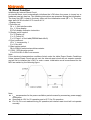
Initializing by Internal Reset Circuit
An internal reset circuit automatically initializes the LCM when the power is turned on or
hardware reset pin has low. The following instructions are executed during the initialization.
The busy flag (BF) is kept in the busy state until the initialization ends (BF = 1). The busy
state lasts for 40 ms after VCC rises to 4.5 V.
1.Display clear
2.Function set:
DL = 1; 8-bit interface data
N = 1; 2-line display
EXT=0;disable extension instruction.
3. Display on/off control:
D = 0; Display off
C = 0; Cursor off
P = 0; Page 1 of font table(DDRAM data b8=0)
4. Entry mode set:
I/D = 1; Increment by 1
S = 0; No shift
5. Bias resistor select:
Rb1=0;Rb2=0 select external bias resistor.
6. COM、SEG direction select:
C1=0;C2=0;S1=0;S2=0 not reverse.
Note:
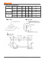
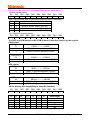
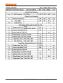
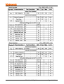
If the electrical characteristics conditions listed under the table Power Supply Conditions
Using Internal Reset Circuit are not met, the internal reset circuit will not operate normally
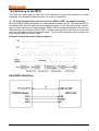
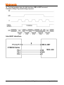
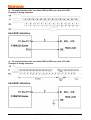
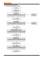
and will fail to initialize the LCM. For such a case, initialization must be performed by the
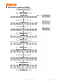
MPU as explain by the following figure.
Note:
l tOFF compensates for the power oscillation period caused by momentary power supply
oscillations.
l Specified at 4.5V for 5V operation,and at 2.7V for 3V operation.
l For if 4.5V is not reached during 5V operation,teh internal reset circuit will not operate
normally.
TC1602J-01WD0_A00
Page 24 of 29