1
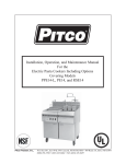
IMPORTANT FOR FUTURE REFERENCE
Please complete this information and retain this manual
for the life of the equipment:
Model #: ___________________________
Serial #: ___________________________
Date Purchased:
___________________
Installation and Operation Manual
For Gas Fryer
NO OPTION/STAND ALONE
Covering Model
VF35
1
L20-418 Rev 0 9/13
TO THE PURCHASER, OWNER AND STORE MANAGER
Please review these warnings prior to posting them in a prominent location for reference
TO THE PURCHASER
Post in a prominent location the instructions to be followed in the event
that an operator smells gas. Obtain this information from your local gas
supplier.
FOR YOUR PROTECTION
DO NOT store or use gasoline or other flammable vapors and liquids in
the vicinity of this or any other appliance.
Do not spray aerosols in the vicinity of this appliance when it is in
operation.
WARNING
Improper installation, operation, alteration, adjustments, service or
maintenance can cause property damage, injury or death. Read the
installation, operating and maintenance instructions thoroughly before
installing, operation, servicing this appliance.
WARNING
Installation, maintenance and repairs should be performed by a Pitco
Authorized Service and Parts (ASAP) company technician or other
qualified personnel. Installation, maintenance or repairs by an
unauthorized and unqualified personnel will void the warranty.
WARNING
Installation and all connections must be made according to local
codes in force. In the absence of local codes in North America, the
installation must conform with the National Fuel Gas Code, ANSI
Z223.1/NFPA 54 or the Natural Gas and Propane Installation Code
CSA B149.1 as applicable. In Australia, the appliance must be
installed in compliance with AS/NZS 5601.
WARNING
During the warranty period if a customer elects to use a non-original part
or modifies an original part purchased from Pitco and/or its Authorized
Service and Parts (ASAP) companies, this warranty will be void. In
addition, Pitco and its affiliates will not be liable for any claims, damages
or expenses incurred by the customer which arises directly or indirectly,
in whole or in part, due to the installation of any modified part and/or
received from an unauthorized service center.
WARNING
Adequate means must be provided to LIMIT the movement or this
appliance without depending on the gas or electrical cord connection.
Single appliances equipped with legs must be stabilized by installing
anchor straps. All appliances equipped with casters must be stabilized
by installing restraining chains.
WARNING
DO NOT alter or remove structural material on the appliance to
accommodate placement under a ventilation hood.
WARNING
If the appliance is equipped with a power cord and it is damaged, it must
be replaced by a Pitco Authorized Service and Parts (ASAP) company
technician or a similarly qualified person in order to avoid a hazard.
WARNING
The power supply must be disconnected before servicing, maintaining
or cleaning this appliance.
WARNING
The appliance is NOT jet stream approved. DO NOT clean the
appliance with a water jet.
WARNING
DO NOT attempt to move this appliance or transfer hot liquids from one
container to another when the unit is at operating temperature or filled
with hot liquids. Serious personal injury could result if skin comes in
contact with the hot surfaces or liquids.
WARNING
DO NOT use an open flame to check for gas leaks!
WARNING
DO NOT sit or stand on this appliance. The appliance’s front panel,
tank, splash back, tank cover, work shelf, drain board is not a step.
Serious injury could result from slipping, falling or contact with hot
liquids.
WARNING
NEVER use the appliance as a step for cleaning or accessing the
ventilation hood. Serious injury could result from slips, trips or from
contacting hot liquids.
WARNING
The oil/shortening level should NOT fall below the minimum indicated
level line at any time. The use of old shortening can be dangerous as it
will have a reduced flash point and be more prone to surge boiling.
WARNING
Completely shut the appliance down when shortening/oil is being
drained from the appliance. This will prevent the appliance from heating
up during the draining and filling process. Serious injury can occur.
WARNING
This appliance is intended for indoor use only.
WARNING
DO NOT operate appliance unless all panels and access covers are
attached correctly.
WARNING
It is recommended that this appliance be inspected by a qualified
service technician for proper performance and operation on a yearly
basis.
WARNING
There is an open flame inside this appliance. The unit may get hot
enough to set nearby materials on fire. Keep the area around the
appliance free from combustibles.
WARNING
DO NOT supply the appliance with a gas that is not indicated on the
data plate. If you need to convert the appliance to another type of fuel,
contact your dealer.
WARNING
If gas flow to appliance is interrupted, or pilots extinguish, wait 5 minutes
before attempting to relight the pilot to allow any residual gas in
appliance to dissipate.
WARNING
Ensure that the appliance can get enough air to keep the flame burning
correctly. If the flame is starved for air, it can give off a dangerous
carbon monoxide gas. Carbon monoxide is a clear odorless gas that
can cause suffocation.
WARNING
Never add oil to the appliance when it is at operating temperature.
Splashing hot oil can cause severe injuries.
WARNING
Never add water to hot oil. Violent boiling can occur causing severe
injury.
WARNING
This appliance is intended for professional use only and should be
operated by fully trained and qualified personnel.
WARNING
To avoid splashing of hot liquid when installed, this fryer must be
restrained either by the manner of installation, or with adequate ties to
prevent tipping.
WARNING
An appliance equipped with casters and a flexible gas line must be
connected to the gas supply with a quick disconnect device. In North
America, gas appliances equipped with casters must be installed with
connectors that comply with the Standard for Connectors for Movable
Gas Appliances, ANSI Z21.69.CSA 6.16 Latest Edition. This
connection should include a quick disconnect device that complies
with the Standard for Quick Disconnect Devices for Use With Gas
Fuel ANSI Z221.41.CSA 6.9 Latest Edition. In Australia, an appliance
equipped with casters and a flexible gas line must be connected to
the gas supply with a quick disconnect device that complies with AS
4627. The hose must comply with AS/NZS 1869 and be class B or D
and have a restraining cable. The restraining cable must not exceed
80% of the length of the flexible gas line.
2
L20-418 Rev 0 9/13
NOTICE
In the event of problems or questions about your order, contact the Pitco Frialator factory at (603) 225-6684.
In the event of problems or questions about your equipment, contact the Pitco Frialator Authorized Service and Parts
representative (ASAP) covering your area, or contact Pitco at the numbers listed above.
MAILING ADDRESS
Pitco Frialator
P.O. Box 501
Concord, NH 03302-0501
SHIPPING ADDRESS
Pitco Frialator
10 Ferry Street
Concord, NH 03301
Standard Accessories
One tube rack
One built-in flue deflector
Two twin size baskets
One drain extension
One drain line clean out rod
Removable basket hanger
9” legs adjustable
3
L20-418 Rev 0 9/13
Table of Contents
NOTICE .................................................................................................................................................................................................... 3 INSTALLATION ...................................................................................................................................................................................... 5 Checking And Unpacking Your New Appliance ................................................................................................................................... 5 Installation Clearances ........................................................................................................................................................................... 5 Leveling The Fryer – Legs/Casters ........................................................................................................................................................ 6 Gas Connection...................................................................................................................................................................................... 7 Fuel Types ............................................................................................................................................................................................. 7 Quick Disconnect Gas Connection ........................................................................................................................................................ 7 Fuel Supply Line Leak and Pressure Testing......................................................................................................................................... 7 Ventilation And Fire Safety Systems ..................................................................................................................................................... 8 Gas Line Requirements.......................................................................................................................................................................... 8 Lighting Instructions.............................................................................................................................................................................. 9 Initial Cleaning ...................................................................................................................................................................................... 9 Daily Cleaning ....................................................................................................................................................................................... 9 Weekly Fryer Cleaning ........................................................................................................................................................................ 10 Thermostat Calibration Check ............................................................................................................................................................. 10 Thermostat Calibration ........................................................................................................................................................................ 11 Filling The Fryer With Liquid Shortening ........................................................................................................................................... 11 Filling The Fryer With Solid Shortening ............................................................................................................................................. 11 Fryer Shut-Down ................................................................................................................................................................................. 11 4
L20-418 Rev 0 9/13
INSTALLATION
Checking And Unpacking Your New Appliance
Your new Pitco appliance has been carefully packed into one crate. Every effort has been made to ensure that it is
delivered to you in perfect condition. Pitco does not assume responsibility for damage or loss incurred in transit.
1. Upon Delivery, inspect for visible shipping damage in the presence of the trucking operator. If something appears
damaged, file a claim for damages regardless of extent.
2. Unpack and inspect unit for damage. Contact the shipper within 15 days and file a concealed damage claim; the
shipper is only responsible for concealed damage for 15 days after delivery.
3. Remove the unit from the shipping pallet:
a: Remove the filter pan, and JIB pan from unit before attempting to
dismount the unit from the shipping base.
4. Do not allow the full weight of the unit to rest on the legs or caster when removing the appliance from the shipping
pallet. The casters can be bent or damaged if too much weight or force is applied to them from improper handling.
5. Check the packing list enclosed with your appliance to ensure that you have received all the parts to the
appliance. If you are missing any parts, contact the dealer from whom the appliance was purchased.
6. Using the front cover of this manual, record the following for warranty service or future reference: 1. Your Pitco
model number. 2. Fryer serial numbers (Found on the inner door of each fryer). 3. The date purchased from
your dealer invoice.
Once you have completed the above, the appliance is ready to be installed.
Installation Clearances
The clearances shown below are for combustible and non-combustible installations and will allow for safe and proper
operation of your appliance.
Back
Sides
Floor
Combustible Construction
Inches (centimeters)
6.0" (15.2cm)
6.0" (15.2cm)
9” (22.86 cm)
Non Combustible Construction
Inches (centimeters)
0.0" (0.0cm)
0.0" (0.0cm)
9” (22.86 cm)
In addition to the above clearances there must also be at least 30 inches (76.2cm) of aisle space in front of the unit.
WARNING
DO NOT obstruct the flow of ventilation air openings around the appliance. Adequate clearance around the appliance is
necessary for servicing and proper component ventilation. Ensure that you meet the minimum clearance requirements
specified in this manual.
WARNING
DO NOT install this appliance next to a water cooker, or use in any way in which water can come in contact with the hot
oil. Splash over of water into hot oil may result in a steam eruption, potentially causing hot oil to be ejected from the
fryer, and creating a burn hazard.
5
L20-418 Rev 0 9/13
Leveling The Fryer – Legs/Casters
CAUTION
To prevent equipment damage and/or personal injury, do not tilt the appliance onto any two of its casters or
legs, or pull the appliance by the splash back.
WARNING
This appliance must be installed with the legs or casters provided by the manufacturer.
WARNING
DO NOT perform leveling procedure when appliance is in operation or full of hot liquids. Serious injury
could result.
When you receive your appliance it is completely assembled with legs or optional casters. This appliance
must be installed with legs or casters; it cannot be curb mounted, or sealed to a base. Curb mounting will
seriously inhibit this appliance’s ability to effect proper component ventilation. The supplied legs or casters
provide the necessary height to meet sanitation requirements and assure adequate air supply for electrical
component ventilation. To level the fryer, use the following procedure.
Required tools: Large pair of water pump pliers, Medium flat blade screwdriver, level 12” long max.
1 Position appliance in final installed location.
2 Apply level across front, and then the left and right side of unit, determine lowest point, and distance to level.
3 Add the distance determined in step 2 to caster or leg on the lowest corner of appliance.
a. Swivel casters- loosen 2 set screws (A)
b. Legs and swivel casters-. Adjust the height of the leg / caster by turning adjustment collar/ foot (B) with water
pump pliers until desired change in height is achieved.
c. Swivel casters only: Retighten set screws (A).
d. Fixed casters- Adjust height by moving wheel and axle to alternate holes in wheel bracket higher or lower as
needed. Refer to Figure 3C “FIXED” type caster.
4 Adjust remaining casters or legs as needed to insure the appliance is supported evenly at each caster/leg
contact point.
Figure 3 Caster and leg types
6
L20-418 Rev 0 9/13
Gas Connection
Your fryer will give you peak performance when the gas supply line is of sufficient size to provide the correct gas
flow. The gas line must be installed to meet the local building codes or National Fuel Gas Code ANSI Z223.1
Latest Edition. In Canada, install the fryer in accordance with CAN/CGA-B149.1 or .2 and local codes. Gas line
sizing requirements can be determined by your local gas company by referring to National Fuel Gas Code,
Appendix C, Table C-4 (natural gas) and Table C-16 (propane). The gas line needs to be large enough to supply
the necessary amount of fuel to all appliances without losing pressure to any appliance.
WARNING
NEVER supply the fryer with a gas that is not indicated on 1the data plate. Using the incorrect gas type will cause
improper operation. If you need to convert the fryer to another type of fuel, contact your dealer.
Fuel Types
Each fryer is equipped to work with one type of fuel. The type of fuel with which the appliance is intended to operate is
stamped on the data plate attached to the inside of the door.
NOTICE
NEVER use an adaptor to make a smaller gas supply line fit the cooker connection. This may not allow proper gas
flow for optimum burner operation, resulting in poor cooker performance.
Quick Disconnect Gas Connection
Gas fryers equipped with casters must be installed with connectors that comply with the Standard for Connectors for
Movable Gas Appliances, ANSI Z223.1 Latest Edition, and Addenda Z21.69A Latest Edition. This connection should
include a quick disconnect device that complies with the Standard for Quick Disconnect Devices for Use With Gas Fuel ,
ANSI Z223.1 Latest Edition. When installing a quick disconnect you must also install a means for limiting the movement
of the fryer. This device will prevent the gas line or the quick disconnect from being strained. The restraining device
should be attached to the cooker on the back panel.
Fuel Supply Line Leak and Pressure Testing
The fuel supply system must be tested before the fryer is used. If the fuel line is going to be tested at a pressure greater
than (>)1/2 PSIG (3.45 kPa), make sure that the fryer is disconnected from the fuel line. If the fuel line is to be tested at a
pressure equal to or less than (<) 1/2 PSIG (3.45 kPa), the fryer can be connected but the unit's gas valve must be
shut. Test all gas line connections for leaks with a solution of soap and water when pressure is applied.
7
L20-418 Rev 0 9/13
Ventilation And Fire Safety Systems
Your new appliance must have proper ventilation to function safely and properly. Exhaust gas temperatures can reach
as high as 1100 °F (593 °C). Therefore, it is very important to install a fire safety system. Your ventilation system
should be designed to allow for easy cleaning. Frequent cleaning and proper maintenance of the ventilation system
and the appliance will reduce the chances of fire. Ventilation and fire safety systems must comply to local and national
codes for US and Canada. Refer to ANSI 83.11 for a list of reference documents that will provide guidance on
ventilation and fire safety systems. For installations in U.S. and Canada, additional information can be obtained from
CSA International, 8501 East Pleasant Valley Road, Cleveland, OH, 44131 or visit their website at www.csainternational.org. In Australia the ventilation system must comply with AS/NZS 5601.0.
It is essential that the appliance be operated only when adequate ventilation is provided. Your ventilation hood should
be properly maintained. A qualified installation professional should ensure that the hood is operating properly in
conjunction with the appliance. Inadequate ventilation may not properly evacuate appliance all emissions. Excessive
or unbalanced ventilation may cause drafts, which could interfere with proper operation of the pilot and burners. Leave
at least 18 inches (47cm) of open space between the flue of the appliance and the intake of the exhaust hood.
WARNING
Ensure that your ventilation system does not cause a down draft at the appliance’s flue opening. A down draft will not
allow the appliance to exhaust properly and will cause overheating, which may cause permanent damage. Damage
caused by down drafts will not be covered by the warranty. NEVER allow anything to obstruct the flow of
combustibles or ventilation exiting the appliance. NEVER place anything on top of the flue area, or block the flue in
any way. Never place a grease condensing drip pan over the flue opening.
WARNING
NEVER connect the ventilation blower or hood directly to the flue of this appliance. The resulting increased flow of air
through the combustion system will cause improper operation, poor temperature recovery, poor ignition and could
extinguish the pilot.
WARNING
Replacing or adding appliances under a pre-existing fire safety system may require modifications to the system.
ALWAYS contact a professional who is qualified in installing, designing and maintaining your fire safety system to
assure that any appliances located under the fire safety system are adequately protected.
If installed in Australia the fryer must be installed in accordance with AS/NZS 5601, local authority and any other
relevant statutory regulations. Flexible hose (if used) must comply with AS/NZS 1869 Class B or D, be of appropriate
internal diameter, be kept as short as possible (not exceed 1.2 meters), must not be kinked and not be in contact with a
hot surface. A chain must be fitted to restrict the fryer movement to no more than 80% of the hose length.
NOTICE
NEVER connect the blower directly to the flue openings. The direct flow of air will cause poor temperature recovery,
poor ignition, inefficient operation of the fryer, and could extinguish the pilot.
Gas Line Requirements
A properly installed gas supply system will deliver 7.0 ± 2.0" w.c. natural gas (12.0 ± 2.0" w.c. LP) to all
appliances connected to the line, operating at full demand.
NOTICE
Do NOT exceed 13.5” W.C. pressure as damage may occur to the gas valve
8
L20-418 Rev 0 9/13
Lighting Instructions
a.
b.
c.
d.
e.
Fill kettle before lighting.
Turn combination gas valve knob to “PILOT” position.
Depress valve knob and light pilot. With pilot burning, hold knob depressed for 60 seconds.
Release knob, pilot should remain lit.
DO NOT TURN COMBINATION GAS VALVE KNOB TO THE “ON” POSITION UNTIL
VESSEL IS FULL OF WATER OR SHORTENING. TURNING THE KNOB TO “ON”
WITH VESSEL EMPTY WILL DAMAGE THE VESSEL OR COMPONENTS AND VOID
WARRANTY.
Relighting - wait 5 minutes before attempting to relight the pilot to allow for any gas in the fryer to
dissipate.
Initial Cleaning
When the fryer is shipped, many of its parts are covered with a thin coat of oil for protection. Before the
fryer is ready for cooking it must be cleaned. This will remove the oil coating and any foreign matter that
may have accumulated during storage and shipment. Perform the cleaning as described below.
a. Fill the vessel with water.
b. Turn the fryer gas valve knob to the “ON” position. Allow the fryer to bring the water to a
low boil and add one packet of Pitco fryer cleaner or a mild, low sudsing detergent and
allow water to continue to boil for a minute, making sure water does not boil over.
c. Turn the gas valve knob to the “PILOT” position and allow fryer to soak with the hot
water for 15 minutes.
d. Using the fryer cleaning brush, scrub the inside of the fryer to remove protective coating.
e. When cleaning is complete, turn the gas valve knob to the “OFF” position and drain the
water into a container suitable for hot water and dispose of it.
f. When the tank has cooled, rinse it thoroughly with cool water. Continue to rinse the tank
until the cleaner has been rinsed, thoroughly from the tank.
g. Using a clean dry cloth, wipe out all of the water. Be very thorough removing the water,
because any residual water will cause hot oil to splatter out of the fryer. Close the drain
valve and remove container.
h. Now that the tank is clean, you are ready to fill and operate the fryer. Refer to
instructions on adding shortening to the fryer.
.
NOTICE
Do not leave the fryer unattended during cleaning. Never let the water level go below the "Min Level" mark on the
back of the tank
CAUTION
Mild steel tanks must be wiped down/coated with oil to keep the tank from rusting.
Daily Cleaning
Should be performed to maintain peak operation and appearance.
a. Wipe up any shortening that spills onto the exterior of the fryer. This should be done with
a clean soft cloth while the oil is still warm.
b. Use warm water with a mild detergent to clean surfaces. Be careful not to get water in
the shortening and to remove any detergent from the fry tank.
c. Use a nonabrasive scouring powder or pad to clean stains if necessary.
d. Perform the weekly boil out cleaning of your fryer described below.
9
L20-418 Rev 0 9/13
Weekly Fryer Cleaning
This cleaning should include a complete draining of the fryer and a boil out.
a. You will need a container large enough to hold 1 1/2 times the oil in one tank. This
container should also be able to withstand 4000 F oil temperatures.
b. Shut fryer gas system OFF completely before performing procedures to ensure unit does not
come on during any part of the cleaning operation.
c. Drain the oil from the fryer and discard or save for reuse. Remove tube rack/mesh tube screens
and remove any large debris from the bottom of the fry tank. Once clean, return tube rack/mesh
screens to the fry tank. Close the drain valve and fill the fry tank with water and noncaustic
detergent. Relight gas system pilot, following the lighting instructions.
d. Turn the fryer gas valve knob to the “ON” position. Allow the fryer to bring the water to a low
boil and add one packet of Pitco fryer cleaner or a mild,low sudsing detergent and allow water
to continue to boil for a minute, making sure water does not boil over.
e. Turn the gas valve knob to the “PILOT” position and allow fryer to soak with the hot water for 15
minutes.
f. Using the fryer cleaning brush, scrub the inside of the fryer to remove protective coating.
g. When cleaning is complete, turn the gas valve knob to the “OFF” position and drain the water
into a container suitable for hot water and dispose of it.
h. When the tank has cooled, rinse it thoroughly with cool water. Continue to rinse the tank until
the cleaner has been rinsed, thoroughly from the tank.
i. Using a clean dry cloth, wipe out all of the water. Be very thorough removing the water,
because any residual water will cause hot oil to splatter out of the fryer. Close the drain valve
and remove container.
j. Now that the tank is clean, you are ready to fill and operate the fryer. Refer to instructions on
adding shortening to the fryer.
WARNING
Gas units installed with casters must have a restraining device. This device must be connected at all times that the
fryer is connected to the gas supply. If it is disconnected for any reason, it must be reconnected
Thermostat Calibration Check
NOTICE
Thermostat calibration requires that the temperature of the fryer be raised above boiling. Therefore, you will need to
drain the water from the fryer and fill it with oil. Before removing the water, perform the initial cleaning of the fryer.
Cleaning the fryer now will prevent you from having to drain the oil and refill with water later.
To perform the calibration check detailed below you will need a digital thermometer.
a. Place the tip of the thermometer in the shortening approximately 1" above the temperature
sensors.
b. Set the thermostat at 325°F and wait for the temperature reading on the thermometer to
rise. As the temperature rises toward 325°F watch the thermometer closely.
c. If the shortening temperature reaches 350°F and the burners DO NOT turn off, turn the
thermostat down. Keep lowering the thermostat setting until the burners go out.
CAUTIONI
If the burners do not turn off at the lowest thermostat setting, the thermostat could be defective. Contact your
representative immediately
d. Let the fryer cycle 4 to 6 times before checking the temperature. Compare the
thermometer temperature against the thermostat setting. If the values are more than 5°F
apart, calibrate the thermostat using the appropriate calibration procedure in this manual.
10
L20-418 Rev 0 9/13
Thermostat Calibration
Millivolt thermostats
a. Set the thermostat dial to 325o F.
b. Remove the thermostat dial by pulling the knob straight out. DO NOT rotate the dial.
c. Hold the outside of the shaft so it does not move. Use the tip of a small, flat tip screw driver to
scrape away the sealing compound from the adjustment screw.
d. Turn the adjustment screw clockwise to lower the temperature setting and counterclockwise
to raise the temperature. One quarter turn changes the temperature approximately 25o F.
e. Turn the adjustment until the burners turn on at 325o F. Replace the knob and allow the fryer
to cycle 4 to 6 times. Check the temperature of the thermometer against the thermostat dial. If
it is greater than 5o F difference, repeat the calibration procedure.
f. When the calibration is correct, remove the thermometer and replace the tube screen.
Filling The Fryer With Liquid Shortening
a. Make sure the drain valve is completely closed.
b. Fill the fryer with oil to the "Oil Level" line marked on the back of the tank.
Filling The Fryer With Solid Shortening
a. Make sure the drain valve is completely closed.
b. Remove the screen covering the tubes.
c. Cut the shortening into cubes no larger than 1". ALWAYS pack the shortening below,
between, and on top of the burner tubes. DO NOT leave any large air gaps. Use care when
packing the solid shortening in the tank. DO NOT bend or break the temperature sensor
probes. If these are damaged the fryer will not function properly.
d. Once the fryer is packed with shortening, the shortening must be melted.
e. To melt shortening, manually pulse the burners ON and OFF using the thermostat until the shortening
is liquidized enough to cover the heat tubes. This will protect the tank and components from damage
and extend the life of the oil.
Fryer Shut-Down
There are two shutdown modes of fryer operation, STANDBY and COMPLETE. The standby mode
removes the ability for the fryer's main burners to cycle. Complete shutdown turns off the gas supply to
the fryer. Shut down the fryer by:
STANDBY Turn the thermostat to OFF. Turn the gas valve clockwise to the PILOT position. The cooker is now in
Standby and can remain this way for only brief periods of time. NEVER leave the cooker in standby overnight.
COMPLETE To completely shut down the cooker, push and turn the gas valve counterclockwise to the OFF
position. The fryer is now completely shut down and can be cleaned and filtered.
11
L20-418 Rev 0 9/13
In the event of problems with or questions
about your order, please contact the Pitco
Frialator factory at:
(603)-225-6684 World Wide
Website Address: www.pitco.com
In the event of problems with or questions about
your equipment, please contact the Pitco Frialator
Authorized Service and Parts representative
(ASAP) covering your area, or contact Pitco at the
number listed to the left.
MAILING ADDRESS – P.O. BOX 501, CONCORD, NH 03302-0501
SHIPPING ADDRESS – 10 FERRY STREET, CONCORD, NH 03301
12
L20-418 Rev 0 9/13