1
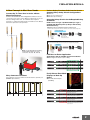
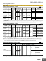
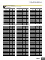
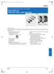
Safety Light Curtain/Multi-beam Safety Sensor F3SN-A/F3SN-B/F3SH-A CSM_F3SN-A_F3SN-B_F3SH-A_DS_E_4_1 • Lineup includes Type-4 Sensors (F3SN-A/F3SH-A) and Type-2 Sensors (F3SN-B) with IEC, EN, and JIS standard certification. USA UL compliance for applications for the USA or Canada. • Protective height equals the Sensor length to perfectly meet user needs. • Protective height: 189 to 1,822 mm Operating range: 7 or 10 m • Setting Console enabling setting parameters for any model. • LED bar for beam alignment or easy confirmation in error mode. • A complete lineup of accessories. Be sure to read the “Safety Precautions” on page 28 and the “Precautions for All Safety Sensors” . Features Two Forms of Safety from OMRON: Safety Light Curtains and Multibeam Safety Sensors Safety Light Curtains for Finger Protection F3SN-A@@@@P14 • Operating range: 7 m • Smallest detectable object: 14 mm dia. (beam gap: 9 mm) • Protective height: 189 to 1,125 mm Multi-beam Safety Sensor for Body Protection F3SH-A09P03 • Operating range: 10 m • Number of beams: 4 (beam gap: 300 mm) Presence Detection in Danger Zones (Horizontal Installation) F3SN-A@@@@P40/P70 F3SN-B@@@@P40/P70 • Operating range: 10 m • Smallest detectable object: 40 mm dia. (beam gap: 30 mm) or 70 mm dia. (beam gap: 60 mm) • Protective height: F3SN-A: 217 to 1,822 mm F3SN-B: 217 to 1,777 mm Safety Light Curtains for Hand Protection F3SN-A@@@@P25 F3SN-B@@@@P25 • Operating range: 10 m • Smallest detectable object: 25 mm dia. (beam gap:15 mm) • Protective height: 217 to 1,822 mm 1 F3SN-A/F3SN-B/F3SH-A A New Concept to Meet User Needs Connect Up To Three Sets in Series without Mutual Interference Combine Standard Models with Linking Models with Connectors to connect up to three sets in series. Wiring is required only for one set instead of wiring all three sets, as would have been required previously, to enable protecting all sides of hazardous areas. Mutual interference protection is also provided. Various Safety Functions Built into the Sensor. Supports Many Safety Circuit Configurations ● Interlocks ● Auto-reset or manual reset ● External relay monitoring Select the Safety Circuits for the Required Safety Standards Build Circuits for Type 4 (F3SN-A/F3SH-A) or Type 2 (F3SN-B) with No Relay Units (2 Relays with Forcibly Guided Contacts) ● Reduced Costs and Reduced Space Requirements A built-in external relay monitor function eliminates the need for Safety Relay Units. No Safety Relay Units F39-JC@A Safety Light Curtains F3SN-A F3SH-A F3SN-B G7SA Welded relay detection circuit is possible with two Relays with Forcibly Guided Contacts. Contactors Motor ● Reduced Wiring and Easy Maintenance One-touch connection with connectors on both end to prevent wiring mistakes. Connectors F39-JC@B Note: Use models with the following model number suffixes for series connection: -01, -03, -04, and -05 Safety Light Curtains F3SN-A F3SH-A F3SN-B Motor Contactors Special Relay Unit F3SP-B1P LED Bars for Easier Application Align Beams with the LED Bar for Easier Installation ● Beam Alignment Indicators (Green Only) Application not possible. Sensor ON but not stable. Dependable application possible. Many Connector Variations Select the type of connector that best suits the machine. (Consult your OMRON representative.) Easily Discern Error Mode Displays to Back Up Safety ● Error Indication Example (Red Only) Confirmation from two directions. Standard: No model No. suffix Interlock input line or reset input line wiring mistake or broken line. Model No. suffix: -01 Model No. suffix: -02 Model No. suffix: -03 Model No. suffix: -04 Model No. suffix: -05 Relay welded, return time too long, or external relay monitor line wiring mistake or broken line. Communications line (RS-485) wiring mistake, broken line, or other error. Control output short, wiring mistake, or control output circuit fault. 2 F3SN-A/F3SN-B/F3SH-A Ordering Information Main Units (Connecting Cables are not included with the Main Units. The connecting cables must be purchased separately.) F3SN-A Safety Light Curtains (Type 4) Detection capability Beam gap 14 mm-dia. (for finger protection) 9 mm 25 mm-dia. (for hand protection) 15 mm 40 mm-dia. (for presence protection) 30 mm 70 mm-dia. (for presence detection) 60 mm Appearance Infrared Operating range 0.2 to 7 m Number of beams 21 to 125 189 to 1125 (odd mm numbers only) (every 18 mm) 13 to 120 0.2 to 10 m Protective height 7 to 60 5 to 30 217 to 1822 mm (every 15 mm) 217 to 1807 mm 277 to 1777 mm Connector for seriesconnection Model *1 *2 No F3SN-A@@@@P14 Yes F3SN-A@@@@P14-01 No F3SN-A@@@@P25 Yes F3SN-A@@@@P25-01 No F3SN-A@@@@P40 Yes F3SN-A@@@@P40-01 No F3SN-A@@@@P70 Yes F3SN-A@@@@P70-01 *1. The @@@@ in the model numbers indicates the protective height (in mm). Refer to “Safety Light Curtain Model List” on page 4 for model number details. *2. Safety Light Curtains with model numbers ending in -02 through -05, provided with different connector configurations, are also available as options. Refer to page 2 for details. Consult with your dealer or OMRON representative when ordering these models. F3SN-B Safety Light Curtains (Type 2) Detection capability Beam gap 25 mm-dia. (for hand protection) 15 mm 40 mm-dia. (for presence detection) 30 mm 70 mm-dia. (for presence detection) 60 mm Appearance Infrared Operating range Number Protective of beams height Output *1 13 to 119 217 to (non1807 mm continuous) 0.2 to 10 m 7 to 60 217 to (non1807 mm continuous) 5 to 30 PNP transistor output 277 to 1777 mm Connector for seriesconnection Model *2 *3 No F3SN-B@@@@P25 Yes F3SN-B@@@@P25-01 No F3SN-B@@@@P40 Yes F3SN-B@@@@P40-01 No F3SN-B@@@@P70 Yes F3SN-B@@@@P70-01 *1. Models with NPN transistor outputs are also available as options. For details on the method for securing safety by using an NPN transistor for output, contact your OMRON representative. *2. The @@@@ in the model numbers indicates the protective height (in mm). Refer to “Safety Light Curtain Model List” on page 4 for model number details. *3. Safety Light Curtains with model numbers ending in -02 through -05, provided with different connector configurations, are also available as options. Refer to page 2 for details. Consult with your dealer or OMRON representative when ordering these models. F3SH-A Multi-beam Safety Sensors (Type 4) Beam gap 300 mm (for whole body protection) Appearance Operating range 0.2 to 10 m Infrared Number of beams 4 Outermost beam gap Connector for seriesconnection Model * No F3SH-A09P03 Yes F3SH-A09P03-01 900 mm * Safety Light Curtains of model numbers ending in -02 through -05, provided with different connector configurations, are also available as options. Refer to page 2 for details. Consult with your dealer or OMRON representative when ordering this model. 3 F3SN-A/F3SN-B/F3SH-A Safety Light Curtain Model List : F3SN-B@@@@P@@ safety light curtains are also available. F3SN-A@@@@P14(-01) Model Protective height Number of beams Model Protective height Number of beams Model Protective height Number of beams F3SN-A0189P14(-01) 189 21 F3SN-A0513P14(-01) 513 57 F3SN-A0837P14(-01) 837 93 F3SN-A0207P14(-01) 207 23 F3SN-A0531P14(-01) 531 59 F3SN-A0855P14(-01) 855 95 F3SN-A0225P14(-01) 225 25 F3SN-A0549P14(-01) 549 61 F3SN-A0873P14(-01) 873 97 F3SN-A0243P14(-01) 243 27 F3SN-A0567P14(-01) 567 63 F3SN-A0891P14(-01) 891 99 F3SN-A0261P14(-01) 261 29 F3SN-A0585P14(-01) 585 65 F3SN-A0909P14(-01) 909 101 F3SN-A0279P14(-01) 279 31 F3SN-A0603P14(-01) 603 67 F3SN-A0927P14(-01) 927 103 F3SN-A0297P14(-01) 297 33 F3SN-A0621P14(-01) 621 69 F3SN-A0945P14(-01) 945 105 F3SN-A0315P14(-01) 315 35 F3SN-A0639P14(-01) 639 71 F3SN-A0963P14(-01) 963 107 F3SN-A0333P14(-01) 333 37 F3SN-A0657P14(-01) 657 73 F3SN-A0981P14(-01) 981 109 F3SN-A0351P14(-01) 351 39 F3SN-A0675P14(-01) 675 75 F3SN-A0999P14(-01) 999 111 F3SN-A0369P14(-01) 369 41 F3SN-A0693P14(-01) 693 77 F3SN-A1017P14(-01) 1017 113 F3SN-A0387P14(-01) 387 43 F3SN-A0711P14(-01) 711 79 F3SN-A1035P14(-01) 1035 115 F3SN-A0405P14(-01) 405 45 F3SN-A0729P14(-01) 729 81 F3SN-A1053P14(-01) 1053 117 F3SN-A0423P14(-01) 423 47 F3SN-A0747P14(-01) 747 83 F3SN-A1071P14(-01) 1071 119 F3SN-A0441P14(-01) 441 49 F3SN-A0765P14(-01) 765 85 F3SN-A1089P14(-01) 1089 121 F3SN-A0459P14(-01) 459 51 F3SN-A0783P14(-01) 783 87 F3SN-A1107P14(-01) 1107 123 F3SN-A0477P14(-01) 477 53 F3SN-A0801P14(-01) 801 89 F3SN-A1125P14(-01) 1125 125 F3SN-A0495P14(-01) 495 55 F3SN-A0819P14(-01) 819 91 Protective height Number of beams Protective height Number of beams F3SN-A@@@@P25(-01), F3SN-B@@@@P25(-01) Model Protective height Number of beams Model Model F3SN-A0217P25(-01) 217 13 F3SN-A0757P25(-01) 757 49 F3SN-A1297P25(-01) 1297 F3SN-A0232P25(-01) 232 14 F3SN-A0772P25(-01) 772 50 F3SN-A1312P25(-01) 1312 86 F3SN-A0247P25(-01) 247 15 F3SN-A0787P25(-01) 787 51 F3SN-A1327P25(-01) 1327 87 F3SN-A0262P25(-01) 262 16 F3SN-A0802P25(-01) 802 52 F3SN-A1342P25(-01) 1342 88 F3SN-A0277P25(-01) 277 17 F3SN-A0817P25(-01) 817 53 F3SN-A1357P25(-01) 1357 89 F3SN-A0292P25(-01) 292 18 F3SN-A0832P25(-01) 832 54 F3SN-A1372P25(-01) 1372 90 F3SN-A0307P25(-01) 307 19 F3SN-A0847P25(-01) 847 55 F3SN-A1387P25(-01) 1387 91 F3SN-A0322P25(-01) 322 20 F3SN-A0862P25(-01) 862 56 F3SN-A1402P25(-01) 1402 92 F3SN-A0337P25(-01) 337 21 F3SN-A0877P25(-01) 877 57 F3SN-A1417P25(-01) 1417 93 F3SN-A0352P25(-01) 352 22 F3SN-A0892P25(-01) 892 58 F3SN-A1432P25(-01) 1432 94 F3SN-A0367P25(-01) 367 23 F3SN-A0907P25(-01) 907 59 F3SN-A1447P25(-01) 1447 95 F3SN-A0382P25(-01) 382 24 F3SN-A0922P25(-01) 922 60 F3SN-A1462P25(-01) 1462 96 F3SN-A0397P25(-01) 397 25 F3SN-A0937P25(-01) 937 61 F3SN-A1477P25(-01) 1477 97 F3SN-A0412P25(-01) 412 26 F3SN-A0952P25(-01) 952 62 F3SN-A1492P25(-01) 1492 98 F3SN-A0427P25(-01) 427 27 F3SN-A0967P25(-01) 967 63 F3SN-A1507P25(-01) 1507 99 F3SN-A0442P25(-01) 442 28 F3SN-A0982P25(-01) 982 64 F3SN-A1522P25(-01) 1522 100 F3SN-A0457P25(-01) 457 29 F3SN-A0997P25(-01) 997 65 F3SN-A1537P25(-01) 1537 101 F3SN-A0472P25(-01) 472 30 F3SN-A1012P25(-01) 1012 66 F3SN-A1552P25(-01) 1552 102 F3SN-A0487P25(-01) 487 31 F3SN-A1027P25(-01) 1027 67 F3SN-A1567P25(-01) 1567 103 F3SN-A0502P25(-01) 502 32 F3SN-A1042P25(-01) 1042 68 F3SN-A1582P25(-01) 1582 104 F3SN-A0517P25(-01) 517 33 F3SN-A1057P25(-01) 1057 69 F3SN-A1597P25(-01) 1597 105 F3SN-A0532P25(-01) 532 34 F3SN-A1072P25(-01) 1072 70 F3SN-A1612P25(-01) 1612 106 F3SN-A0547P25(-01) 547 35 F3SN-A1087P25(-01) 1087 71 F3SN-A1627P25(-01) 1627 107 F3SN-A0562P25(-01) 562 36 F3SN-A1102P25(-01) 1102 72 F3SN-A1642P25(-01) 1642 108 F3SN-A0577P25(-01) 577 37 F3SN-A1117P25(-01) 1117 73 F3SN-A1657P25(-01) 1657 109 F3SN-A0592P25(-01) 592 38 F3SN-A1132P25(-01) 1132 74 F3SN-A1672P25(-01) 1672 110 F3SN-A0607P25(-01) 607 39 F3SN-A1147P25(-01) 1147 75 F3SN-A1687P25(-01) 1687 111 F3SN-A0622P25(-01) 622 40 F3SN-A1162P25(-01) 1162 76 F3SN-A1702P25(-01) 1702 112 F3SN-A0637P25(-01) 637 41 F3SN-A1177P25(-01) 1177 77 F3SN-A1717P25(-01) 1717 113 F3SN-A0652P25(-01) 652 42 F3SN-A1192P25(-01) 1192 78 F3SN-A1732P25(-01) 1732 114 F3SN-A0667P25(-01) 667 43 F3SN-A1207P25(-01) 1207 79 F3SN-A1747P25(-01) 1747 115 F3SN-A0682P25(-01) 682 44 F3SN-A1222P25(-01) 1222 80 F3SN-A1762P25(-01) 1762 116 F3SN-A0697P25(-01) 697 45 F3SN-A1237P25(-01) 1237 81 F3SN-A1777P25(-01) 1777 117 F3SN-A0712P25(-01) 712 46 F3SN-A1252P25(-01) 1252 82 F3SN-A1792P25(-01) 1792 118 F3SN-A0727P25(-01) 727 47 F3SN-A1267P25(-01) 1267 83 F3SN-A1807P25(-01) 1807 119 F3SN-A0742P25(-01) 742 48 F3SN-A1282P25(-01) 1282 84 F3SN-A1822P25(-01) 1822 120 85 4 F3SN-A/F3SN-B/F3SH-A F3SN-A@@@@P40(-01), F3SN-B@@@@P40(-01) Protective height Model F3SN-A@@@@P70(-01), F3SN-B@@@@P70(-01) Number of beams Protective height Model Number of beams Protective height Model Number of beams F3SN-A0217P40(-01) 217 7 F3SN-A1027P40(-01) 1027 34 F3SN-A0277P70(-01) 277 5 F3SN-A0247P40(-01) 247 8 F3SN-A1057P40(-01) 1057 35 F3SN-A0337P70(-01) 337 6 F3SN-A0277P40(-01) 277 9 F3SN-A1087P40(-01) 1087 36 F3SN-A0397P70(-01) 397 7 F3SN-A0307P40(-01) 307 10 F3SN-A1117P40(-01) 1117 37 F3SN-A0457P70(-01) 457 8 F3SN-A0337P40(-01) 337 11 F3SN-A1147P40(-01) 1147 38 F3SN-A0517P70(-01) 517 9 F3SN-A0367P40(-01) 367 12 F3SN-A1177P40(-01) 1177 39 F3SN-A0577P70(-01) 577 10 F3SN-A0397P40(-01) 397 13 F3SN-A1207P40(-01) 1207 40 F3SN-A0637P70(-01) 637 11 F3SN-A0427P40(-01) 427 14 F3SN-A1237P40(-01) 1237 41 F3SN-A0697P70(-01) 697 12 F3SN-A0457P40(-01) 457 15 F3SN-A1267P40(-01) 1267 42 F3SN-A0757P70(-01) 757 13 F3SN-A0487P40(-01) 487 16 F3SN-A1297P40(-01) 1297 43 F3SN-A0817P70(-01) 817 14 F3SN-A0517P40(-01) 517 17 F3SN-A1327P40(-01) 1327 44 F3SN-A0877P70(-01) 877 15 F3SN-A0547P40(-01) 547 18 F3SN-A1357P40(-01) 1357 45 F3SN-A0937P70(-01) 937 16 F3SN-A0577P40(-01) 577 19 F3SN-A1387P40(-01) 1387 46 F3SN-A0997P70(-01) 997 17 F3SN-A0607P40(-01) 607 20 F3SN-A1417P40(-01) 1417 47 F3SN-A1057P70(-01) 1057 18 F3SN-A0637P40(-01) 637 21 F3SN-A1447P40(-01) 1447 48 F3SN-A1117P70(-01) 1117 19 F3SN-A0667P40(-01) 667 22 F3SN-A1477P40(-01) 1477 49 F3SN-A1177P70(-01) 1177 20 F3SN-A0697P40(-01) 697 23 F3SN-A1507P40(-01) 1507 50 F3SN-A1237P70(-01) 1237 21 F3SN-A0727P40(-01) 727 24 F3SN-A1537P40(-01) 1537 51 F3SN-A1297P70(-01) 1297 22 F3SN-A0757P40(-01) 757 25 F3SN-A1567P40(-01) 1567 52 F3SN-A1357P70(-01) 1357 23 F3SN-A0787P40(-01) 787 26 F3SN-A1597P40(-01) 1597 53 F3SN-A1417P70(-01) 1417 24 F3SN-A0817P40(-01) 817 27 F3SN-A1627P40(-01) 1627 54 F3SN-A1477P70(-01) 1477 25 F3SN-A0847P40(-01) 847 28 F3SN-A1657P40(-01) 1657 55 F3SN-A1537P70(-01) 1537 26 F3SN-A0877P40(-01) 877 29 F3SN-A1687P40(-01) 1687 56 F3SN-A1597P70(-01) 1597 27 F3SN-A0907P40(-01) 907 30 F3SN-A1717P40(-01) 1717 57 F3SN-A1657P70(-01) 1657 28 F3SN-A0937P40(-01) 937 31 F3SN-A1747P40(-01) 1747 58 F3SN-A1717P70(-01) 1717 29 F3SN-A0967P40(-01) 967 32 F3SN-A1777P40(-01) 1777 59 F3SN-A1777P70(-01) 1777 30 F3SN-A0997P40(-01) 997 33 F3SN-A1807P40(-01) 1807 60 Accessories (Optional) Control Unit Appearance Output Relay, 3NO + 1NC Model F3SP-B1P Remarks For connection with the F3SN-A, F3SN-B, and F3SH-A, use F39-JC@B cables fitted with connectors at both ends. OMRON offers many Safety Application Controllers to help you build safety circuits. Refer to Safety Application Controller Product Selection and specifications. 5 F3SN-A/F3SN-B/F3SH-A Setting Console Appearance Model Accessories Branching Connector (1), Connector Cap (1), Special Cable (2 m), Instruction Manual F39-MC11 Maintenance Tool * Appearance Model Applicable Sensors F3SN-A series F3SN-B series F3SH-A series F39-MT11 Accessories Branching Connector (1), Connector Cap (1), Special Cable (2 m), Special Cable with Plug (0.3 m), Instruction Manual * For detail, see the product datasheet (Cat. No. E355). Branching Connector Appearance Model Remarks Purchase this connector when needed additionally for installing the F39-MC11. F39-CN1 Cable with Connector on One End (for Emitter and Receiver Set) Appearance Cable length Specification Model 0.5 m F39-JCR5A 3m F39-JC3A 7m M12 connector (8 pin) F39-JC7A 10 m F39-JC10A 15 m F39-JC15A Cables with Connectors on Both Ends (for Emitter and Receiver Set) Appearance Cable length Specification Model 0.2 m F39-JCR2B 0.5 m F39-JCR5B 1m F39-JC1B 3m F39-JC3B 5m 7m F39-JC7B F39-JC10B 15 m F39-JC15B 20 m F39-JC20B 30 m F39-JC30B 40 m F39-JC40B 0.2 m F39-JCR2C 1m F39-JC1C 7m Series connection or connection with F3SP-B1P F39-JC5B M12 connector (8 pins) 10 m 3m Application M12 connector (8 pins) F39-JC3C F39-JC7C 10 m F39-JC10C 15 m F39-JC15C Connection with F3SP-B1P *1 Connection with G9SA-300-SC *1 *2 *1. Cannot be used for series-connection purpose. *2. When two or more cables have to be used for connection with the G9SA-300-SC, connect the necessary number of F39-JC@B cables to one F39-JC@C cable. (Example) When a 35 m long cable is required, connect two F39-JC10B cables to one F39-JC15C. 6 F3SN-A/F3SN-B/F3SH-A External Indicators (Separate Models for Emitters and Receivers) Appearance Specification Indicator Type Model Emitter F39-A01PR-L Receiver F39-A01PR-D Emitter F39-A01PG-L Receiver F39-A01PG-D Red M12 connector for PNP output Green Note: These indicators are used for connecting with series-connection type emitters/receivers (models ending in -01). (The Indicator must be secured separately for models ending in -04 or -05.) The desired turn-ON timing (type of signal) can be selected on setting console. Mirrors (Reduce Operating Range by 12% with Each Unit) Mirror material Glass mirror Width (mm) Depth (mm) 145 32 Length (mm) Model 406 F39-MLG0406 610 F39-MLG0610 711 F39-MLG0711 914 F39-MLG0914 1,067 F39-MLG1067 1,219 F39-MLG1219 1,422 F39-MLG1422 1,626 F39-MLG1626 1,830 F39-MLG1830 2,134 F39-MLG2134 Spatter Protection Covers (Include Two Pieces for Emitter and Receiver) (Reduces Operating Range by 10% with Each Unit) Appearance Applicable sensor Model F3SN-A@@@@P14 F39-HN@@@@-14 F3SN-A@@@@P25(-01) F3SN-A@@@@P40(-01) F3SN-A@@@@P70(-01) F3SN-B@@@@P25 F3SN-B@@@@P40 F3SN-B@@@@P70 F39-HN@@@@-25 F3SH-A09P03(-01) F39-HH09-03 Note: The same 4-digit numbers as the protective heights (@@@@ in the light curtain type names) are substituted by @@@@ in the model names. Spatter Protection Slit Covers (Include Two Pieces for Emitter and Receiver) * Appearance Applicable sensor Model Slit width: 1.15 mm Slit width: 0.6 mm F3SN-A@@@@P14(-01) F39-HS@@@@A-14 F39-HS@@@@B-14 F3SN-A@@@@P25(-01) F3SN-A@@@@P40(-01) F3SN-A@@@@P70(-01) F3SN-B@@@@P25 F3SN-B@@@@P40 F3SN-B@@@@P70 F39-HS@@@@A-25 F39-HS@@@@B-25 F3SH-A09P03(-01) F39-HSH09A-03 F39-HSH09B-03 * Operating range will decrease substantially. Refer to “Specifications” on page 12 for details. Environment-resistant Enclosures (Package of a Pipe, Gasket, and Bracket) * Appearance Applicable sensor Model F3SN-A@@@@P14(-01) F39-HP@@@@-14 F3SN-A@@@@P25(-01) F3SN-A@@@@P40(-01) F3SN-A@@@@P70(-01) F3SN-B@@@@P25 F3SN-B@@@@P40 F3SN-B@@@@P70 F39-HP@@@@-25 F3SH-A09P03(-01) F39-HPH09-03 * Purchase 2 sets when using both an emitter and a receiver. 7 F3SN-A/F3SN-B/F3SH-A Multi-beam Sensor Support Stands/Mirror Stands Appearance Specification Model Stand unit Materials Base:STKM (base) SUS304 (leaf spring) Pipe, bolts and nuts: SUS304 Weight: 11.8 kg Mounting bracket Materials: Aluminum Weight: 250 g Remarks F39-ST1 Minimum order quantity: 1 pc. (In total, 2 stands are required for each F3SH-A: one for the emitter and the other for the receiver.) F39-L22 Minimum order quantity: 1 pc. (In total, 6 brackets are required for each F3SH-A: 3 units each for emitter and receiver. These brackets are not required for the F39-MLG series reflection mirrors, since these mirrors are supplied together with a specially designed adapter.) Mounting Brackets for Sensors (Optional) Appearance Specification Model Free-location bracket Materials: Zinc die-cast (zinc plating) Note: Not provided with an angle deflection mechanism for beam control. Free-location bracket Materials Sensor fixing element: Zinc die-cast (zinc plating) Mounting bracket: Iron (zinc plating) Remarks F39-L19 Minimum order quantity: 1 pc. F39-L20 Minimum order quantity: 1 pc. Note: Provided with an angle deflection mechanism for beam control * Use these brackets for sensors having an operating range where no intermediate bracket is required (with an operating range of less than 640 mm). Test Rods (Optional) Appearance Applicable sensor F3SN-A@@@@P14(-01) F3SN-A@@@@P25(-01) Specification Model 14 mm-dia. (provided with the sensor) F39-TR14 Used for checking the setting condition of single-beam floating blanking F39-TR23 Used for checking the setting condition of two-beam floating blanking F39-TR32 25 mm-dia. (provided with the sensor) F39-TR25 *1 Used for checking the setting condition of single-beam floating blanking F39-TR40 *2 *1. Also provided with the F3SN-B@@@@P25. *2. Also provided with the F3SN-A@@@@P40 and F3SN-B@@@@P40. 8 F3SN-A/F3SN-B/F3SH-A Specifications (For details, refer to the instruction manual.) Main Units F3SN-A/F3SH-A Model *8 Standalone Series connection Item F3SN-A@@@@P14 *1 F3SN-A@@@@P25 *1 F3SN-A@@@@P40 *1 F3SN-A@@@@P70 *1 F3SH-A09P03 F3SN-A@@@@P14-01 *1 *2 F3SN-A@@@@P25-01 *1 F3SN-A@@@@P40-01 *1 F3SN-A@@@@P70-01 *1 F3SH-A09P03-01 Sensor type Type 4 Safety Light Curtain Setting tool connection Connectable Safety category Category 4, 3, 2, 1, or B Detection capability Opaque objects: 14 mm in diameter Opaque objects: 25 mm in diameter Opaque objects: 40 mm in diameter Opaque objects: 70 mm in diameter Beam gap (P) 9 mm 15 mm 30 mm 60 mm 300 mm Number of beams (n) 21 to 125 (odd numbers only) 13 to 120 7 to 60 5 to 30 4 Protective height (PH) 189 to 1125 mm PH = n × P 217 to 1822 mm PH = (n – 1) × P + 37 217 to 1807 mm PH = (n – 1) × P + 37 277 to 1777 mm PH = (n – 1) × P + 37 Lens diameter 9 mm × 4.6 mm Diameter 9 mm Operating range 0.2 to 7 m 0.2 to 10 m Response time (under stable light incident condition) ON to OFF: 10 to 15.5 ms max. OFF to ON: 40 to 62 ms max. Startup waiting time 1 s max. Power supply voltage (Vs) 24 VDC ±10% (ripple p-p 10% max.) Outermost beam gap Current consumption (no load) --- --- --900 mm ON to OFF: 10 ms max. OFF to ON: 40 ms max. Emitter Up to 50 beams: 140 mA max., 51 to 85 beams: 155 mA max., 86 beams and more: 170 mA max. 140 mA max. Receiver Up to 50 beams: 100 mA max., 51 to 85 beams: 110 mA max., 86 beams and more: 120 mA max. 100 mA max. Light source (emitted wavelength) Infrared LED (870 nm) Effective aperture angle (EAA) Within ±2.5° for the emitter and receiver at a detection distance of at least 3 m according to IEC 61496-2 Control outputs (OSSD) Two PNP transistor outputs, load current 300 mA max., residual voltage 2 V max. (except for voltage drop due to cable extension), allowable capacity load 0.075 μ F, leak current 2 mA max. Auxiliary output (non-safety output) One PNP transistor output, load current 50 mA max., residual voltage 2 V max. (except for voltage drop due to cable extension) External indicator output (non-safety output) *3 One PNP transistor output, load current 40 mA max., residual voltage 2 V max. (except for voltage drop due to cable extension) Output operation mode Control output: Light-ON Auxiliary output: Dark-ON (can be changed by the F39-MC11) External indicator output: Light-ON (can be changed by the F39-MC11) *3 Input voltage Test input, interlock selection input, reset input, and external relay monitor input voltages; ON voltage: 9 to 24 V (with a sink current 3 mA max.), OFF voltage: 0 to 1.5 V or open Emitter Power indicator (green), interlock indicator (yellow), lockout indicator (red), test indicator (orange), error mode indicator (3 red), light intensity level indicator (green: 5 levels) Receiver OFF-state indicator (red), ON-state indicator (green), lockout indicator (red), blanking indicator (green: F3SN-A only), Power indicator (green: F3SH-A only), error mode indicator (3 red), light intensity level indicator (green: 5 levels) Indicators Mutual interference prevention function *3 Time-shared beam projection system by series connection Series connections • Number of series connected light curtains: Up to 3 sets • Number of beams: Up to 240 beams • Length of the series connection cable: 3 m max. Test functions • Self test (when power is turned ON and while power is supplied, one cycle during response time) • External test (emission stop function by test input) Safety functions • • • • Auto-reset/manual reset (interlock) *4 EDM (External Device Monitor) Fixed blanking *5 Floating blanking *5 Connection method M12 connector (8 pins) Protective circuits Output short-circuit protection, power supply reverse polarity protection Ambient temperature Operating: −10 to 55°C, storage: −30 to 70°C (with no icing or condensation) Ambient humidity Operating/storage: 35% to 95% (with no condensation) Ambient operating light intensity Incandescent lamp: 3000 Ix max. (light intensity on the receiver surface) Sunlight: 10000 Ix max. (light intensity on the receiver surface) Insulation resistance 20 MΩ min. (at 500 VDC) Dielectric strength 1000 VAC 50/60 Hz 1 min. Degree of protection IEC Standard IP65 Vibration resistance Malfunction: 10 to 55 Hz, 0.7-mm double amplitude, 20 sweeps in X, Y and Z directions Shock resistance Malfunction: 100 m/s2, 1000 times in X, Y and Z directions • Auto-reset/manual reset (interlock) *4 • EDM (External Device Monitor) 9 F3SN-A/F3SN-B/F3SH-A Model *8 Item Standalone Series connection F3SN-A@@@@P14 *1 F3SN-A@@@@P25 *1 F3SN-A@@@@P40 *1 F3SN-A@@@@P70 *1 F3SH-A09P03 F3SN-A@@@@P14-01 *1 *2 F3SN-A@@@@P25-01 *1 F3SN-A@@@@P40-01 *1 F3SN-A@@@@P70-01 *1 F3SH-A09P03-01 Materials Case: Aluminum, end cap: Zinc die-cast, optical cover: PMMA (acrylic resin), Cable: Oil-resistant PVC Weight (packed state) Weight (g) = (Detection width) × 2.4 + α + β Detection width of 189 to 639 mm: α = 700, Detection width of 652 to 1,267 mm: α = 800, Detection width of 1,282 to 1,822 mm: α = 900, Model with no suffix or −01: β = 0, Model with suffix −02, −03, or −05: β = 100, Model with suffix −04: β = 200 Accessories Test rod *6, instruction manual, error mode label, mounting brackets (top and bottom), mounting brackets (intermediate) *7 Applicable standards IEC61496-1, EN61496-1 Type 4 ESPE (Electro-Sensitive Protective Equipment) IEC61496-2 Type 4 AOPD (Active Opto-electronic Protective Devices) *1. The 4 digits in @@@@ in the model number represent the protective height. Use the formula given in the information on protective height specifications to calculate the height. For example, if the beam gap is 9 mm, and the No. of beams is 21, the protective height will be 9 × 21 = 189 mm. The model with this protective height is F3SN-A0189P14. *2. F3SN-A@@@@P14-01 is a customized model. Consult with your dealer or OMRON representative when ordering this model. *3. Only models ending in -01, -03, -04, or -05 have this output and functionality. *4. For the factory setting, the manual reset mode is set to the “start/restart” interlock. Using the F39-MC11 can select either the start interlock or the restart interlock. *5. For the factory setting, the function is not set. It can be enabled with the F39-MC11. *6. Not provided with the F3SN-A@@@@P70 and F3SH-A. *7. The intermediate mounting bracket is supplied with the following types: Types which have the total length of the light curtain from 640 mm to 1280 mm: 1 set for each of emitter and receiver. Types which have the total length of the light curtain over 1280 mm: 2 sets for each of emitter and receiver. *8. Models with different connector configurations are also available as options. Refer to “Many Connector Variations” on page 2. 10 F3SN-A/F3SN-B/F3SH-A F3SN-B ( Different from specifications of F3SN-A) Model *6 Item Sensor type Setting tool connection Safety category Detection capability Beam gap (P) Number of beams (n) Protective height (PH) Lens diameter Operating range Response time (under stable light incident condition) Startup waiting time Power supply voltage (Vs) Current consumption (no load) F3SN-B@@@@P25 Type 2 Safety Light Curtain Not connectable Category 2, 1, or B Opaque objects: 25 mm in diameter 15 mm 13 to 119 (noncontinuous) 217 to 1807 mm PH = (n − 1) × P + 37 mm Diameter 9 mm 0.2 to 10.0 m ON to OFF: 10 to 15 ms max. OFF to ON: 40 to 60 ms max. 1 s max. 24 VDC ±10% (ripple p-p 10% max.) F3SN-B@@@@P40 Opaque objects: 40 mm in diameter 30 mm 7 to 60 (noncontinuous) 217 to 1807 mm PH = (n − 1) × P + 37 mm F3SN-B@@@@P70 Opaque objects: 70 mm in diameter 60 mm 5 to 30 277 to 1777 mm PH = (n − 1) × P + 37 mm Emitter Up to 50 beams: 140 mA max., 51 to 85 beams: 155 mA max., 86 beams and more: 170 mA max. Receiver Up to 50 beams: 100 mA max., 51 to 85 beams: 110 mA max., 86 beams and more: 120 mA max. Light source (emitted wavelength) Effective aperture angle (EAA) Control outputs (OSSD) *1 Auxiliary output (non-safety output) Output operation mode *1 Input voltage Emitter Indicators Receiver Mutual interference prevention function Series connections Infrared LED (870 nm) Within ±5° for the emitter and receiver at a detection distance of at least 3 m according to IEC 61496-2 Two PNP transistor outputs, load current 300 mA max., residual voltage 2 V max. (except for voltage drop due to cable extension) , allowable capacity load 0.075 μ F, leak current 2 mA max. One PNP transistor output, load current 50 mA max., residual voltage 2 V max. (except for voltage drop due to cable extension) Control output: Light-ON, Auxiliary output: Dark-ON For test input, interlock selection input, reset input, and external relay monitor input voltages; ON voltage: 9 to 24 V (sink current: 3 mA max.), OFF voltage: 0 to 1.5 V or open Power indicator (green), interlock indicator (yellow), lockout indicator (red), test indicator (orange), error mode indicator (3 red), light intensity level indicator (green: 5 levels) OFF-state indicator (red), ON-state indicator (green), lockout indicator (red), Optional function indicator (green), error mode indicator (3 red), light intensity level indicator (green: 5 levels) Time-shared beam projection system by series connection • Number of series connected light curtains: Up to 3 sets • Number of beams: Up to 240 beams • Length of the series connection cable: 3 m max. Connection method Protective circuits Ambient temperature Ambient humidity • Self test (when power is ON and period is 1 s or less) • External test (light emission stop function by test input) • Auto-reset/manual reset (start/restart interlock) • EDM (External Device Monitor) M12 connector (8 pins) Output short-circuit protection, reverse polarity protection Operating: −10 to 55°C, storage: −30 to 70°C (with no icing or condensation) Operating/storage: 35% to 95% (with no condensation) Ambient operating light intensity Insulation resistance Incandescent lamp: 3000 Ix max. (light intensity on the receiver surface) Sunlight: 10000 Ix max. (light intensity on the receiver surface) 20 MΩ min. (at 500 VDC) Dielectric strength Degree of protection Vibration resistance Shock resistance Materials 1000 VAC 50/60 Hz 1 min. IEC Standard IP65 Malfunction: 10 to 55 Hz, 0.7-mm double amplitude, 20 sweeps in X, Y and Z directions Malfunction: 100 m/s2, 1000 times in X, Y and Z directions Case: Aluminum, end cap: Zinc die-cast, optical cover: PMMA (Acrylic resin) Weight (g) = (Detection width) × 2.4 + α + β Detection width of 189 to 639 mm: α = 700, Detection width of 652 to 1,267 mm: α = 800, Detection width of 1,282 to 1,822 mm: α = 900, Model with no suffix or −01: β = 0, Model with suffix −02, −03, or −05: β = 100, Model with suffix −04: β = 200 Test rod *4, instruction manual, mounting brackets (top and bottom), mounting brackets (intermediate) *5, error mode label IEC61496-1, EN61496-1 Type 2 ESPE (Electro-Sensitive Protective Equipment) IEC61496-2 Type 2 AOPD (Active Opto-electronic Protective Devices) Test functions Safety functions *2 *3 Weight (packed state) Accessories Applicable standards *1. A safety circuit has been adopted. Please note that the control logic (ON/OFF) may differ from conventionally used logic. *2. The manual reset mode is set to the “start/restart” interlock. It is impossible to select interlock only or restart interlock only. *3. No floating blanking or fixed blanking function is provided. *4. Not provided with the F3SN-B@@@@P70. *5. The intermediate mounting bracket is supplied with the following types: Types which have the total length of the light curtain from 640 mm to 1280 mm: 1 set for each of emitter and receiver. Types which have the total length of the light curtain over 1280 mm: 2 sets for each of emitter and receiver. *6. Models with different connector configurations are also available as options. Refer to “Many Connector Variations” on page 2. 11 F3SN-A/F3SN-B/F3SH-A Accessories Control Units Item Model G9SA-300-SC * F3SP-B1P Applicable sensor F3SN-A, F3SN-B, F3SH-A Supply voltage 24 VDC ±10% Power consumption 1.7 W DC max. (does not include the sensor’s current consumption) 24 VDC: 0.7 W DC max. (does not include the sensor’s current consumption) Operating time 100 ms max. (does not include the sensor’s response time) 300 ms max. (does not include the sensor’s response time and bounce time) Response time 10 ms max. (does not include the sensor’s response time) 10 ms max. (does not include the sensor’s response time and bounce time) No. of contact 3 NO + 1 NC 3 NO Rated load 25 VAC, 5 A (cos diameter = 1), 30 VDC, 5 A L/R = 0 ms 250 VAC, 5 A Rated carry voltage 5A Between sensor’s M12 connector (8 pins) Other Terminal block Relay output Connection method Weight (packed state) Approx. 280 g Accessory Instruction manual Approx. 300 g * For further details on the G9SA-300-SC, refer to the G9SA-300-SC instruction manual. Setting Console Item External Indicators Model F39-MC11 Model Applicable sensor F3SN-A, F3SH-A Supply voltage 24 VDC ±10% (provided from the sensor) Connection method Cable (included) Weight (packed state) 360 g Accessories One branching connector, 2-m cable, one connector cap, instruction manual F39-A01PR-L (Emitter) F39-A01PR-D (Receiver) Item For details on the setting console, refer to the instruction manual provided with the product. F39-A01PG-L (Emitter) F39-A01PG-D (Receiver) Applicable sensor F3SN-A@@@@P@@-01(-03, -04, -05) * F3SH-A09P03-01 Light source Red LED Supply voltage 24 VDC ±10% (provided from the sensor) Current consumption 50 mA max. (provided from the sensor) Connection method M12 connector (8 pins) Weight (packed state) Approx. 80 g Green LED * The indicator must be secured separately for models ending in “-04” or “-05.” For the F3SN-B, only light-ON mode can be used. Spatter Protection Slit Covers Model F39-HS@@@@A-14 F39-HS@@@@B-14 Item Applicable sensor Operating range (typical value) * Distance that does not cause mutual interference (typical value) F39-HS@@@@A-25 F39-HSH09A-03 F39-HS@@@@B-25 F39-HSH09B-03 F3SN-A@@@@P@@(-01), F3SN-B@@@@P@@(-01), F3SH-A09P03(-01) F3SN-A@@@@P14(-01) When one cover is used 3m 2m 5.5 m 3.5 m When two covers are used 1m 0.5 m 2m 1m When one cover is used 6.5 m 4.8 m 12.2 m 7.8 m When two covers are used 2.4 m 1.2 m 4.4 m 2.1 m * The maximum distance that can turn ON all of the five light intensity level indicators. Environment-resistant Enclosures Model F39-HP@@@@-14 F39-HP@@@@-25 F39-HPH09-03 Item Applicable sensor F3SN-A@@@@P14(-01) F3SN-A@@@@P@@(-01), F3SN-B@@@@P@@(-01), F3SH-A09P03(-01) Operating range characteristics 0.2 to 6 m 0.2 to 10 m Degree of protection * IP67 (IEC60529) Materials Case: Acrylic resin, rubber: NBR60, mounting bracket: SUS316L, screw: SUS316L * To conform to IP67, tighten the screws according to the “Cautions for Use” as described in the manual packaged together with the product. 12 F3SN-A/F3SN-B/F3SH-A Connections Wiring for Sensor Only Configuration Wiring for the Manual Reset Mode and the EDM Function Emitter S1: S2: S3: External test switch Interlock/lockout reset switch Lockout reset switch (If the switch is not necessary, connect between the reset input and +24 VDC.) K1, K2: Relay that control the dangerous zone, etc. K3: Load, PLC, etc. (used for monitoring) Receiver Emitter cable F39-JC@A-L Receiver cable F39-JC@A-D Wiring for the Auto-reset Mode Emitter Receiver K2 K3 K1 OSSD 1 (Green) +24 V (Brown) EDM input (Red) +24 V (Brown) Auxiliary output (Yellow) S1 S3 (See (See note 1.) note 1.) K2 Open Reset input (Yellow) Interlock selection input (White) (Red) Open Test input (Green) Shield 0 V (Blue) Shield 0 V (Blue) OSSD 2 (White) K1 OSSD 1 (Green) +24 V (Brown) EDM input (Red) RS-485(B) (Pink) Auxiliary output (Yellow) S1 S2 (See (See note 1.) note 1.) +24 V (Brown) Reset input (Yellow) Interlock selection input (White) (Red) Open Test input (Green) Shield 0 V (Blue) RS-485(A) (Gray) K1 (See note 2.) K3 +24 VDC Power supply 0V When the EDM is Not Used When the EDM is not necessary (1) Use the F39-MC11 to disable the EDM. or (2) Disable the EDM by changing the wiring as shown in the figure below, when the auxiliary output is Dark ON. Note: 1. Use very low load type switches. 2. If K3 is not necessary, short-circuit the auxiliary output with the EDM input. Series Connection (Up to 3 Sets) Emitter Using series connection models (model numbers ending in -01, -03, -04, -05) enables series connection as shown in the figure at the right. Either stand-alone models and the series connection models can be used for the light curtains located at the top end. Note: 1. To maintain sensor performance, please use double-ended connector cables for series connection which are the length of F39-JC3B or shorter. Double-ended connector cables that are longer than F39-JC7B cannot be used for series connection. 2. The F3SN and F3SH cannot be connected in series. 3. Series connection is possible for model numbers ending in -04 or -05 (with 0.2 m cable with connectors). Refer to page 2. Cable with Connectors on Both Ends (for Emitter) F39-JCR2B-L, F39-JCR5B-L, or F39-JC3B-L (See notes 1 and 3.) Emitter Cable with Connector on One End (for Emitter) F39-JC@A-L Receiver F3SN-A@@@@P@@(-@@)* Cable with Connectors on Both Ends (for Receiver) F39-JCR2B-D, F39-JCR5B-D, or F39-JC3B-D (See notes 1 and 3.) Receiver F3SN-A@@@@P@@-01 (or -03, -04, -05) * Cable with Connector on One End (for Receiver) * Series connection is F39-JC@A-D possible for the F3SN-B. 13 F3SN-A/F3SN-B/F3SH-A An Example of Safety Circuits Where the F3SP-B1P Controller is Used For category 4 rating (F3SN-A, F3SH-A)/category 2 rating (F3SN-B) Emitter Applicable operation mode • Manual reset mode Receiver S1: S2: S3: PLC IN1 IN2 OUT KM3 S1 S2 H1 A1 L1 J1 H1 X1 Interlock Test selection OSSD 1 OSSD 2 P1 13 23 33 Wiring for the Auto-reset mode 41 Reset Auxiliary output K2 S1 KM1 K1 KM2 K2 K1 External test switch Interlock/lockout reset switch Lockout reset switch (If the switch is not necessary, connect between X1 and H1.) KM1, KM2: Magnetic contactor KM3: Solid-state contactor (G3J) M: 3-phase motor E1: 24 VDC power supply (S82K) PLC: Programmable controller (Used for monitoring. This is not a part of a safety system.) EDM (External device monitoring) S3 H1 L1 J1 Interlock Test selection H1 X1 Reset M A2 +24 VDC E1 0V PE T31 F3SP-B1P T32 14 24 34 KM1 KM1 KM2 KM2 42 Note: 1. If the EDM is not necessary, short-circuit T31 and T32. 2. For the number and arrangement of all terminals on the F3SP-B1P, see the instruction manual packaged together with the F3SP-B1P. 14 F3SN-A/F3SN-B/F3SH-A I/O Circuit Diagrams Internal Circuit Diagram Display *3 Brown +24 V 2 External indicator output Green 3 4 Emitter main circuit Load Test input *1 White 1 Interlock selection input *2 Yellow 7 4 0V Reset input *2 Blue 0V 7 5 6 Gray Pink RS-485(A) RS-485(B) Gray Pink 5 6 Brown 2 Red 8 Receiver main circuit 2 EDM input *2 Green 3 OSSD 1 Load Connector Pins Arrangement White 1 OSSD 2 *3 External indicator output 6 7 Receiver main circuit 1 5 1 Load 4 8 3 2 8 Yellow 4 Load Display Auxiliary output Load Blue 7 7 0V Note: The numbers in ❍ indicate pin numbers of the connectors. The numbers in ● indicate pin numbers of the series connection connectors. *1. Open: normal light emission, short to the +24 VDC: stops light emission *2. Refer to “Connections”, “Wiring for Sensor Only Configuration” on page 13. *3. The section encircled with the dashed line is applied for models ending in -01, -03, -04, or -05 only. Cables with Connector on One End Model Internal wiring 1 F39-JCR5A (0.5 m) F39-JC3A (3 m) F39-JC7A (7 m) F39-JC10A (10 m) F39-JC15A (15 m) 2 4 3 5 3 6 8 2 7 1 4 5 6 7 8 Pin No. Wire color White Brown Green Yellow Gray Pink Blue Red Signal name Wire color Receiver OSSD 2 Emitter Interlock selection input 1 White 2 Brown +24 V +24 V 3 Green OSSD 1 Test input 4 Yellow Auxiliary output Reset input 5 Gray RS-485(A) RS-485(A) 6 Pink RS-485(B) RS-485(B) 7 Blue 0V 0V 8 Red EDM input N.C. 15 F3SN-A/F3SN-B/F3SH-A Output waveform of the OSSD outputs The OSSD outputs will be OFF as shown in the following figure in order to perform the OSSD circuit self-test when the light curtain is in the ON-state. The OSSD circuit diagnosis is correct when this OFF signal is fed back. If the output signal does not contain an OFF signal, the receiver determines that there is an output circuit or wiring failure and goes into the lockout condition. The number of OFF signals depends on the number of light curtains connected in series. (See the chart at left.) In the same way, the OSSD outputs will be ON as shown in the following figure, to perform the OSSD circuit self-test when the light curtain is in the OFF-state. (See the chart below.) Check the input response time of a machine connected to the F3SN-A carefully to ensure the machine will not malfunction due to the OFF signal. Response time Response time ON ON OSSD1, 2 OSSD1, 2 OFF OFF OFF signal OFF signal Approx. 130 µs Approx. 25 µs 160 to 200 µs Note: This chart indicates the instance of 2 light curtains series connection. No. of light curtains connected in series No. of OFF signals within the response time No. of light curtains connected in series No. of ON signals within the response time No 1 No 1 2 light curtains 2 2 light curtains 2 3 light curtains 3 3 light curtains 3 16 F3SN-A/F3SN-B/F3SH-A Names and Functions of Parts Emitter (F3SN-A/ F3SN-B/ F3SH-A) Test indicator (Orange) * Lockout indicator (Red) Interlock indicator (Yellow) Power indicator (Green) Error mode indicator (Red) Light intensity level indicator (Green) Receiver (F3SN-A) OFF-state indicator (Red) ON-state indicator (Green) Error mode indicator (Red) Light intensity level indicator (Green) Error mode indicator (Red) Light intensity level indicator (Green) Error mode indicator (Red) Light intensity level indicator (Green) Lockout indicator (Red) Blanking indicator (Green) * Receiver (F3SN-B) OFF-state indicator (Red) ON-state indicator (Green) Lockout indicator (Red) Optional function indicator (Green) * Receiver (F3SH-A) OFF-state indicator (Red) ON-state indicator (Green) Lockout indicator (Red) Power indicator (Green) * * These indicators flash to indicate the need for preventive maintenance when the total ON time exceeds 30,000 hours. (Models without this flashing function are also available as options. An “-NT” to the model number. Ask your OMRON representative for details.) 17 F3SN-A/F3SN-B/F3SH-A Function Power indicator Lit when power is supplied (always lit): F3SN-A, F3SH-A Emitter Lit when power is supplied, flashing when the F39-MC11 is connected: F3SH-A Receiver * Interlock indicator Lit during interlock condition Lockout indicator Flashing during lockout condition Test indicator Lit during external test * ON-state indicator Lit when OSSD outputs are in ON-state OFF-state indicator Lit when OSSD outputs are in OFF-state Blanking indicator (F3SN-A only) Lit when blanking is set, flashing when the F39-MC11 is connected * Optional function indicator (F3SN-B only) Flashing after a lapse of 30,000 hours * These indicators flash to indicate the need for preventive maintenance when the total ON time exceeds 30,000 hours. (Models without this flashing function are also available as options. An “-NT” to the model number. Ask your OMRON representative for details.) 1 2 3 4 5 Light intensity level 200% and above of ON threshold level 150 to 200% of ON threshold level Light intensity level indicator 100 to 150% of ON threshold level Lit Not lit 75 to 100% of ON threshold level 50 to 75% of ON threshold level Less than 50% of ON threshold level A B C Cause of error The Interlock selection input line or the reset input line is not wired correctly or became open. Relay contact is welded. Releasing time of the relay takes too long. The EDM input line is not wired correctly or became open. Error mode indicator Communication line (RS-485) is not wired correctly, became open, or causes other errors. One of the OSSD outputs is shorted or is not wired correctly. Other failure in OSSD outputs. Flashing Not lit Mutual interference. Interference light is received. Types of the receiver and emitter are not the same. Numbers of the receiver and emitter connected in series are not the same. External noise. Internal hardware failure of the receiver or the emitter. Engineering Data (Typical Examples) Angular range (Angle of elevation) Angular range (Angle of rotation) F3SN-A1107P14 F3SN-A1107P14 F3SN-A1107P14 200 Positive vertical direction 4 3 1 Positive horizontal direction 2 4 6 8 10 Distance X (m) Negative horizontal direction −100 0 −1 −3 −300 Positive direction for emitter 2 3 1 4 Negative direction for emitter Positive direction for receiver 6 8 Distance X (m) 0 −1 Positive direction for emitter 2 4 Negative direction for emitter 6 8 Distance X (m) −2 Negative direction for receiver −4 Horizontal direction 4 2 −2 Negative vertical direction −200 Positive direction for receiver 2 100 0 Angle θ (°) 300 Angle θ (°) Distance Y (mm) Parallel operating range −3 Negative direction for receiver −4 Vertical direction Y θ Y θ X X X X 18 F3SN-A/F3SN-B/F3SH-A Dimensions Main Units (Unit: mm) Refer to the User’s Manual (SCEE-713) for the dimensions of models with different connector configurations (model numbers ending in “-02” to “-05”). F3SN-A@@@@P@@(-01) F3SN-B@@@@P@@(-01) F3SN-A@@@@P@@-01 14 Connector cap 17.3 20.8 Mounting screw holes 2 mounting holes 6. 5 dia. 20 2 mounting brackets 8 22 (16) Four, M5 2 P F 30 28 Intermediate bracket Two, M5 22 5.5 C2 (Protective height) C1 (Protective height) 27 Two, M5 9.25 (41.8) 38 E 15 15 B 11 A B 2 mounting holes M5 up-set hexagon bolt F Beam 1 15 11 D 13.5 32 16 45 46.9 4 mounting holes 2 mounting holes 5.5 20 30 9 dia. Dimensions according to the model can be calculated by using the following equations. • F3SN-A@@@@P14(-01) • F3SN-A@@@@P25(-01)/P40(-01)/P70(-01), F3SN-B@@@@P25(-01)/ P40(-01)/P70(-01) Dimension C2 (protective height): 4 digits in the model name Dimension C1 (protective height): 4 digits in the model name Dimension A = C2 + 86 Dimension A = C1 + 64 Dimension B = C2 + 54 Dimension B = C1 + 32 Dimension D = 15.5 Dimension D = 18.5 Dimension E = C2 – 9 Dimension E = C1 – 37 Dimension F: See the table below. Dimension F: See the table below. Dimension P = 9 C2 (protective height) Number of intermediate Mounting Bracket Dimension F (See note.) C1 (protective height) Number of intermediate Mounting Bracket Dimension F (See note.) to 0620 0 --- to 0640 0 --- 0621 to 1125 1 F = B/2 0641 to 1280 1 F = B/2 1281 to 1822 2 F = B/3 Note: If value F obtained from the above equation is not used, set F to 670 mm or less. Dimension P: See the table below. Detection capability Dimension P 25 15 40 30 70 60 19 F3SN-A/F3SN-B/F3SH-A F3SH-A09P03 F3SH-A09P03-01 F3SH-A09P03-01 14 Connector cap 17.3 20.8 Mounting screw holes 2 mounting brackets 2 mounting holes 6.5 dia. 20 8 22 (16) Four, M5 4 beam mark 2 484.5 30 28 27 Two, M5 22 5.5 Two, M5 9.25 (41.8) 38 937 900 15 15 969 1001 11 Intermediate bracket 969 2 mounting holes M5 up-set hexagon bolt 484.5 300 4 beams 1 18.5 15 13.5 32 16 45 46.9 4 mounting holes 2 mounting holes Mounting Precautions 5.5 20 30 9 dia. Connector cable 1. The intermediate bracket (3) (see Mounting brackets (intermediate)) is shown on the left-hand side of the sensor as an example. If the intermediate bracket (3) is on the right-hand side of the sensor then the mounting holes must also be on the right-hand side. 2. When using with the cable bent, allow at least the dimensions shown on the right. (Minimum bending radius of cable: R36 mm.) R36 mm 80 mm min. 80 mm min. R36 mm Connector cable 20 F3SN-A/F3SN-B/F3SH-A Accessories Mounting Bracket (Top and Bottom) 5.5 6.5 dia. 24 32 9.25 14 13.5 20 9 dia. 4-30° 14.2 dia. 22 dia. Four, R2.15 45 Material: Iron (zinc plating) 4.3 30 30 Note: Provided with the product. Mounting Brackets (Intermediate) 2 25 R2 max. 11 2 16 1 22 17 12 22 30 22 16 Material: Iron (zinc plating) 10 42 20 M5 × 8 bracket fixing screw 2.3 6.5 dia. 11 13.75 11 18 33 Note: Provided with the product. The number of brackets required depends on the total length of the Sensor. 22 Intermediate bracket (3) 38 11 30 Intermediate bracket (1) Intermediate bracket (2) 21.25 15 M4 × 6 sensor fixing screw 5.5 19 5.5 9 dia. Accessories (Optional) Cables with Connector on One End F39-JCR5A (L = 0.5 m) F39-JC3A (L = 3 m) F39-JC7A (L = 7 m) F39-JC10A (L = 10 m) F39-JC15A (L = 15 m) L* 39.5 15 dia. Waterproof connector Color: Emitter (gray) Receiver (black) Vinyl insulated round cable 6.6 mm dia. 8 cores (4 twisted pairs) (conductor cross sectional area: 0.3 mm2/ insulation outside diameter: 1.15 mm dia.) Standard length: L * L = 3, 7, 10, 15 m Cables with Connectors on Both Ends F39-JCR2B (L = 0.2 m) F39-JCR5B (L = 0.5 m) F39-JC1B (L = 1 m) F39-JC3B (L = 3 m) F39-JC5B (L = 5 m) F39-JC7B (L = 7 m) F39-JC10B (L = 10 m) F39-JC15B (L = 15 m) F39-JC20B (L = 20 m) F39-JC30B (L = 30 m) F39-JC40B (L = 40 m) F39-JCR2C (L = 0.2 m) F39-JC1C (L = 1 m) F39-JC3C (L = 3 m) F39-JC7C (L = 7 m) 39.5 15 dia. 43 15 dia. Waterproof connector Color: Emitter (gray) Receiver (black) L F39-JC10C (L = 10 m) F39-JC15C (L = 15 m) Waterproof connector Vinyl insulated round cable 6.6 mm dia. 8 cores (4 twisted pairs) (conductor cross sectional area: 0.3 mm2/ insulation outside diameter: 1.15 mm dia.) Standard length: L 21 F3SN-A/F3SN-B/F3SH-A Control Unit F3SP-B1P Emitter Terminal Allocations Receiver NC NC L1 H1 X1 A1 13 23 33 41 H1 J1 91 Indicators: PWR (green), K1 (orange), K2 (orange) NC NC T31 T32 PE A2 24, M3 10.5 14 24 34 42 NC P1 Mounting screw holes 5.9 7 × 5 = 35 Two, 4.2 dia. or M4 4.6 dia. 13 max. 9 76 max. 63 84±0.3 43 5.6 9 45 max. R2.3 5 35±0.3 111 max. 22 F3SN-A/F3SN-B/F3SH-A Branching Connector (supplied with F39-MC11) Setting Console F39-MC11 F39-CN1 1 2 3 4 8 M12 7 6 Communications jack 18 13.6 5 32.1 CN1 17.7 4 3 52.8 22 Communications connection indicator M12 12 24.7 56 CN3 1 2 13.6 CN2 Function indicator Two, 8 dia. (spot facing depth: 2 mm) 10 Channel display 3 M12 Channel keys 15 4 Two, 4.5 dia. 5 8 Mode display 6 2 1 Up key 7 136 Right key Down key Left key CN1 Connector cable CN2 Sensor CN3 Setting console Enter key Cancel key 50 External Indicators Mirrors F39-A01PR-L/-D F39-A01PG-L/-D F39-MLG@ 145 102 Eight, 7 dia. 52 Can be fitted to the F39-ST1 cylindrical mounting rod (42 dia. ±1) (accessory). 32 L 30 dia. 24 Lighting part M 104.3 96 13 9.2 Waterproof connector 34 Model L (mm) M (mm) F39-MLG0406 445 487 F39-MLG0610 648 690 F39-MLG0711 749 792 F39-MLG0914 953 995 F39-MLG1067 1105 1148 F39-MLG1219 1257 1300 F39-MLG1422 1461 1503 F39-MLG1626 1664 1706 F39-MLG1830 1867 1910 F39-MLG2134 2172 2214 23 F3SN-A/F3SN-B/F3SH-A Spatter Protection Covers Protection cover F39-HN@@@@-14 F39-HN@@@@-25 F39-HH09-03 32 L* 10 * L is as follows. Spatter Protection Slit Covers F39-HS@@@@A(B)-14 F39-HS@@@@A(B)-25 F39-HS09A(B)-03 Materials: PC (transparent area) ABS (non-transparent area) F39-HN@@@@-14 F39-HS@@@@A(B)-14 L = @@@@ mm F39-HN@@@@-25 F39-HS@@@@A(B)-25 L = @@@@ – 22 mm F39-HH09-03 F39-HS09A(B)-03 L = 915 mm Mounting dimensions Fixing bracket 32.6 37.3 37.3 Materials: SUS 9.87 14 Water-resistant Case Multi-beam Sensor Support Stand/Mirror Stand F39-HP@@@@-14 F39-HP@@@@-25 F39-HPH09-03 F39-ST1 156 32 156 61 dia. 57.5 dia. Four, 14-dia. drillings Mounting bracket 8 M4 × 12 screw 42.7 dia. 1300 110 dia. Case 180 L (depends on the length of housing of each model) 180 dia. 12 Mounting Bracket F39-L22 M8 × 30 Hexagon socket head screw 3 28 32.5 26 3 42.9 dia. 8 2 8 16 24 Two, M5 34 32 20 M6 hexagon socket head check bolt 74 dia. Two, R3 16 R2.8 30 9 dia. 24 F3SN-A/F3SN-B/F3SH-A Wall Mounting Bracket F39-L18 90° 33 18 15.5 12.25 2 5.5 9 dia. 30° 30 4.3 Eight, R2.15 20 22 dia. 14.2 dia. 30 38 Free-location Bracket Mounting F39-L19 5 8.5 Emitter cover or receiver cover 30 5 18 3.3 11 (6.4) 1.5 30 (40) 5.5 dia. 24 10 5 10.8 M5 up-set hexagon bolt 15 7 37 M5 up-set hexagon bolt (4.7) (15.5) Free-location Bracket 20 10 (32.3) 25.5 F39-L20 10.5 5.5 dia. 24 30.5 43 32.75 17.75 12 12 5 19.3 M4 up-set hexagon bolt 6.5 6 (14) 20 (15.5) 23 15.5 9 dia. 20 (4.7) M5 up-set hexagon bolt 6.5 dia. 11 (4.7) 5.5 0.8 25.25 10 (15) Side mounting (30.5) (43) (30) M4 up-set hexagon bolt (14) 23 (44) 30 M5 up-set hexagon bolt (15) 30 Emitter cover or receiver cover Back mounting M4 up-set hexagon bolt (44) (23) (15) Emitter cover or receiver cover 30 30 (44) (14) (4.7) (43) M5 up-set hexagon bolt 25 F3SN-A/F3SN-B/F3SH-A Connection Circuit Examples An Example of Safety Circuits Where No Controller Is Used For Category 4 Rating (F3SN-A, F3SH-A)/Category 2 Rating (F3SN-B) Emitter Receiver Applicable operation mode • Manual reset mode • Using the EDM function S1: External test switch S2: Interlock/lockout reset switch KM1, KM2: Safety relay with forcibly guided contacts (G7SA) or magnetic contactor KM3: Solid-state contactor (G3J) M: 3-phase motor E1: 24 VDC power supply (S82K) PLC: Programmable controller (Used for monitoring. This is not a part of a safety system.) S1 Shield 0 V (Blue) OSSD 2 (White) OSSD 1 (Green) Auxiliary output (Yellow) EDM input (Red) +24 V (Brown) RS-485(B) (Pink) +24 V (Brown) Reset input (Yellow) Interlock selection input (White) (Red) Open Test input (Green) Shield 0 V (Blue) RS-485(A) (Gray) KM3 Timing Chart Light incident Light interrupted External test switch (S1) KM1 Reset switch (S2) KM1 KM1 KM2 S2 KM2 KM2 OSSD KM1, KM2 N.O. contact KM1, KM2 N.C. contact M +24 VDC E1 0V IN OUT PLC input * PLC PLC output * The output operation mode of the auxiliary output is the Dark-ON output mode. An Example of Safety Circuits Where the G9SA-301 Safety Relay Unit is Connected For category 4 rating (F3SN-A, F3SH-A)/category 2 rating (F3SN-B) Emitter Receiver Applicable operation mode • For sensor • Auto-reset mode • Disable the EDM monitor function (by setting on the F39-MC11, *1.) • For safety relay unit • Manual reset mode • Use the feedback loop • Use the emergency stop switch *2 S1: S2: S3: +24 VDC E1 0V OSSD 2 (White) 12 22 *2 KM1 11 21 S3 KM2 Shield 0 V (Blue) OSSD 1 (Green) +24 V (Brown) EDM input (Red) Open PLC Auxiliary output (Yellow) S1 +24 V (Brown) Interlock selection input (White) Open Test input (Green) Reset input (Yellow) Open (Red) 0 V (Blue) Shield RS-485(A) (Gray) RS-485(B) (Pink) IN1 IN2 OUT KM3 T11 T12 T31 T32 a K2 K1 13 23 33 41 Emergency stop switch (S3) K1 K2 K1 JP b PE T21 6 K2 a b Control Circuit External test switch (S1) Reset switch (S2) 3 4 1 Timing Chart Light interrupted M KM2 A2 External test switch Reset switch Emergency stop switch (direct opening contacts) (A165E or A22E) KM1, KM2: Magnetic contactor KM3: Solid-state contactor (G3J) M: 3-phase motor E1: 24 VDC power supply (S82K) PLC: Programmable controller (Used for monitoring. This is not a part of a safety system.) Light incident KM1 S2 A1 *1. The F39-MC11 setting console cannot be connected to the F3SN-B. Therefore, shortcircuit the auxiliary output terminal and the EDM input. *2. If emergency stop switch is not necessary, connect the OSSD 1 directly to T12 terminal and connect the OSSD 2 directly to T23 terminal. 2 5 1 2 3 4 5 6 OSSD K1, K2 N.O. contact KM1, KM2 N.O. contact K1, K2 N.C. contact T23 T22 A B 14 24 34 42 KM1, KM2 N.C. contact G9SA-301 KM1 KM2 PLC input 1 Depends on the operation mode of the auxiliary output PLC input 2 PLC output 26 F3SN-A/F3SN-B/F3SH-A Examples of Safety Circuits Where G9SA-300-SC Safety Relay Unit is Connected (1) For only safety light curtain in auto-reset mode For category 4 rating (F3SN-A, F3SH-A)/category 2 rating (F3SN-B) S1: KM1, KM2: M: E1: Receiver Emitter Note: 1. F3SN-A’s EDM function and auxiliary output cannot be used. 2. Normal operation is performed when the switch S1 is released, and external diagnosis is performed when it is short-circuited. 3. Do not connect anything to the C1, D1, D2, E1, and E2 terminals. F3SN-A/F3SN-B/F3SH-A Series KM1 F39-JC@@C-L F39-JC@@C-D External test switch Magnetic contactor 3-phase motor 24 VDC power supply (S82K) KM2 E1 S1 (See note 2.) Timing Chart J1 Vcc A1 A2 T11 T12 Vcc H1 Y1 23 33 KM1 OSSD 2 OSSD 1 External diagnosis 13 X1 +24 V E1 0V Light incident Light interrupted F Receiver connector K3 Black K1 K3 K2 K3 K1 KM2 K2 Emitter connector Gray External test switch (S1) K3 GND K1 K2 T21 T22 F3SN-A/-B/F3SH-A OSSD K3 M GND C1 G1 D1 D2 E1 E2 14 24 KM1 G9SA-300-SC 34 K3 N.C. contact KM2 K3 N.O. contact K1, K2 N.C. contact K1, K2 N.O. contact KM1, KM2 N.C. contact KM1, KM2 N.O. contact (2) Safety light curtain connected with two channel emergency stop switch inputs in manual reset mode For category 4 rating (F3SN-A, F3SH-A)/category 2 rating (F3SN-B) S1: S2: S3: KM1, KM2: M: E1: Receiver Emitter Note: 1. F3SN-A’s EDM function and auxiliary output cannot be used. 2. Normal operation is performed when the switch S3 is released, and external diagnosis is performed when it is short-circuited. 3. Do not connect anything to the C1, D1, D2, E1, and E2 terminals. Emergency stop switch S1 11 21 12 22 F3SN-A/F3SN-B/F3SH-A Series KM1 F39-JC@@C-L S2 F39-JC@@C-D Emergency stop switch Reset switch (momentary action switch) External test switch Magnetic contactor 3-phase motor 24 VDC power supply (S82K) KM2 E1 S3 (See note 2.) J1 Vcc A1 A2 T11 T12 Vcc H1 Y1 23 Timing Chart 33 KM1 OSSD 2 OSSD 1 External diagnosis 13 X1 +24 V E1 0V Light incident Light interrupted F Receiver connector K3 Black K1 K3 K2 K3 K1 KM2 K2 Emitter connector Gray Reset switch (S2) K3 GND K1 K2 T21 T22 External test switch (S3) K3 M GND C1 G1 D1 D2 E1 G9SA-300-SC E2 14 KM1 24 Limit switch (S1, S2) 34 KM2 OSSD K3 N.C. contact K3 N.O. contact K1, K2 N.C. contact K1, K2 N.O. contact KM1, KM2 N.C. contact KM1, KM2 N.O. contact 27 F3SN-A/F3SN-B/F3SH-A Safety Precautions This catalog is intended as a guide for product selection. Be sure to use the instruction manual provided with the product for actual operation. Regulations and Standards F3SN-A/F3SH-A F3SN-B 1. “Type Certification” specified in the Chapter 44. 2 of the Industrial Safety and Health Law in Japan does not apply to independent F3SN-A/F3SH-A Sensors. This law applies to systems incorporating the Sensor. When using the F3SN-A/F3SH-A Sensor in Japan as a “safety device for presses or shearing machines,” as specified in the Chapter 42 of the same law, apply for certification for the overall system. 2. (1) The F3SN-A/F3SH-A is electro-sensitive protective equipment (ESPE) in accordance with European Union (EU) Machinery Directive Annex IV, B, Safety Components, Item 1. (2) The F3SN-A/F3SH-A complies with the following regulations and standards: 1. EU Regulations • Machinery Directive: Directive 98/37/EC • EMC Directive: Directive 2004/108/EC 1. “Type Certification” specified in the Chapter 44. 2 of the Industrial Safety and Health Law in Japan does not apply to independent units of the F3SN-B sensor. This law applies to systems incorporated with the sensors. When using the F3SN-B sensor in Japan as a “safety device for presses or shearing machines” as specified in the Chapter 42 of the same law, apply for certification as a system. 2. (1) The F3SN-B is electro-sensitive protective equipment (ESPE) in accordance with European Union (EU) Machinery Directive Annex IV, B, Safety Components, Item 1. (2) The F3SN-B complies with the following regulations and standards: 1. EU Regulations • Machinery Directive: Directive 98/37/EC • EMC Directive: Directive 2004/108/EC 2. European standards: EN61496-1 (TYPE 4 ESPE), prEN61496-2 (TYPE 4 AOPD) 2. European standards: EN61496-1 (TYPE 2 ESPE), prEN61496-2 (TYPE 2 AOPD) 3. International standards: IEC61496-1 (TYPE 4 ESPE), IEC61496-2 (TYPE 4 AOPD) 3. International standards: IEC61496-1 (TYPE 2 ESPE), IEC61496-2 (TYPE 2 AOPD) 4. American standards: UL61496-1 (TYPE 4 ESPE), UL61496-2 (TYPE 4 AOPD), UL508, UL1998, CAN/CSA22.2 No. 14, CAN/CSA22.2 No. 0.8 4. American standards: UL61496-1 (TYPE 2 ESPE), UL61496-2 (TYPE 2 AOPD), UL508, UL1998, CAN/CSA22.2 No. 14, CAN/ CSA22.2 No. 0.8 5. JIS standards: JIS B9704-1 (TYPE 4 ESPE), JIS B9704-2 (TYPE 4 AOPD) 5. JIS standards: JIS B9704-1 (TYPE 2 ESPE), JIS B9704-2 (TYPE 2 AOPD) (3) The F3SN-A/F3SH-A received the following certification from the Third Party Assessment Body UL: • Certificate of UL listing for US and Canadian safety standards Both of which are: TYPE 4 ESPE (UL61496-1), TYPE 4 AOPD (UL61496-2) (3) The F3SN-B received the following certification from the Third Party Assessment Body UL: • Certificate of UL listing for US and Canadian safety standards Both of which are: Type 2 ESPE (UL61496-1), Type 2 AOPD (UL61496-2) 3. The F3SN-A/F3SH-A is designed according to the following standards. To make sure that the F3SN-A/F3SH-A complies with the following standards and regulations, you are asked to design and use it as provided by any other related standards, laws, and regulations. (Underlined regulations are applicable to the F3SN-A only.) Consult UL or other standardization bodies if you have any questions. • EN415-4, prEN691, EN692, prEN693 (European standards) • OSHA 29 CFR 1910.212 (US Industrial Safety and Health Regulation) • OSHA 29 CFR 1910.217 (US Industrial Safety and Health Regulation) • ANSI B11.1 - B11.19 (US standard) • ANSI/RIA 15.06 (US standard) • Guideline Concerning Failsafe Methods for Control Mechanisms in Machine Tools, 28 July 1998 (The Announcement No. 464, Ministry of Health, Labour and Welfare) 3. The F3SN-B is designed according to the following standards. To make sure that the F3SN-B complies with the following standards and regulations, you are asked to design and use it as provided by any other related standards, laws, and regulations. Consult UL or other standardization bodies if you have any questions. • EN415-4 (European standard) • OSHA 29 CFR 1910.212 (US Industrial Safety and Health Regulation) • ANSI/RIA 15.06 (US standard) • Guideline Concerning Failsafe Methods for Control Mechanisms in Machine Tools, 28 September 1998 (The Announcement No. 464, Ministry of Health, Labour and Welfare) 28 F3SN-A/F3SN-B/F3SH-A !WARNING Detection Zone and Intrusion Path Refer to “Precautions for All Safety Sensors” for the installation conditions of Safety Light Curtains. F3SH-A Multi-beam Safety Sensor Model F3SN-A@@@@ P40(-01) F3SN-B@@@@ P40 Install protective structures around the machine so that you must pass through the detection zone of the F3SH-A to reach a hazardous part of the machine. If it is possible for an operator to get between the sensor’s detection zone and the hazardous part of the machine, design the system so that machinery cannot start up automatically. Make sure that machinery cannot restart while the operator is in the hazardous area. Position the switch for restarting machinery in a location from which the status of the hazardous area can be seen clearly. The switch position location must be a place where the switch cannot be operated from within the hazardous area. Failure to do so may result in serious injury. Model F3SN-A@@@@ P70(-01) F3SN-B@@@@ P70 Use of the Fixed Blanking Function (F3SN-A only) After setting the fixed blanking, check that the F3SN-A detects a test rod at any position in the detection zone through which a person can reach the hazardous part of the machine. If any positions are found by check above, install protective structures to prevent intrusion, which the F3SN-A can not detect. Failure to do so may result in serious injury. Safety Distance Always maintain a safe distance (S) between the light curtain and a hazardous part of a machine. Failure to do so causes the machine to fail to stop before an operator reaches the dangerous area and may result in serious injury. Protective height (mm) 217 to 757 Number of beams ON to OFF OFF to ON 10.0 40 787 to 1,297 26 to 43 12.5 50 1,327 to 1,807 44 to 60 15.0 60 Protective height (mm) 277 to 757 7 to 25 Response time Number of beams 5 to 13 Response time ON to OFF OFF to ON 10.0 40 817 to 1,297 14 to 22 12.5 50 1,357 to 1,777 23 to 30 15.0 60 • Response time for series connected types is calculated as follows: (F3SN-A) For 2 sets: Response time (ON to OFF): Response time of Light curtain 1 + Response time of Light curtain 2 + 3 ms Response time (OFF to ON): Response time of Light curtain 1 + Response time of Light curtain 2 + 12 ms For 3 sets: Response time (ON to OFF): Response time of Light curtain 1 + Response time of Light curtain 2 + Response time of Light curtain 3 + 4 ms Response time (OFF to ON): Response time of Light curtain 1 + Response time of Light curtain 2 + Response time of Light curtain 3 + 16 ms • Response time of F3SP-B1P is 10 ms, operation time is 100 ms. Note: When using the F3SP-B1P, determine the safety distance by adding the response time of the F3SP-B1P to that of the F3SN given in the table above. Use of the floating blanking increases the size of the detection capability. To calculate a safety distance, be sure to use the increased size of the detection capability. Failure to do so causes the machine to fail to stop before an operator reaches the dangerous area and may result in serious injury. Refer to the “Precautions for All Safety Sensors” for calculating the Safety distance. Response Time Table Model F3SNA@@@@ P14(-01) Model F3SN-A@@@@ P25(-01) F3SN-B@@@@ P25 Protective height (mm) Number of beams Response time ON to OFF OFF to ON 180 to 450 20 to 50 10.0 40 459 to 765 51 to 85 12.5 50 774 to 1,080 86 to 120 15.0 60 1,089 to 1,125 121 to 125 15.5 62 Protective height (mm) 217 to 772 Number of beams Response time ON to OFF OFF to ON 13 to 50 10.0 787 to 1,297 51 to 85 12.5 40 50 1,312 to 1,822 86 to 120 15.0 60 29 F3SN-A/F3SN-B/F3SH-A Precautions for Correct Use Do not use the product in atmospheres or environments that exceed product ratings. Installation How to Prevent Mutual Interference Series connection (Up to 3 sets, 240 beams, sensor models ending in -01, -03, -04, and -05 are required for series connection) Two or more pairs of the F3SN-A can be connected in series. When connected in series, the F3SN-A sensors generate beams in a time-sharing manner. Thus, they prevent mutual interference and ensure safety. How to attach Mounting Bracket (F39-L19/L20) To fully utilize the performance of sensors, locate the F39-L19/L20 mounting brackets in the number satisfying the dimensions “A” and “B” in the sensor longitudinal direction. • For the F39-L19 Spacing “A”: 670 mm max. • For the F39-L20 Spacing “B”: 400 mm max. B/2 A/2 B A Note: When installing sensors at locations susceptible to vibration and shock, increase the number of mounting brackets. Correct Emitter 1 Installation Receiver 1 Cable for connection F39-JCR2B or F39-JCR5B or F39-JC3B B A Emitter 2 Receiver 2 Receiver B/2 Emitter Incorrect Emitter 1 Receiver 1 A/2 Incorrect Emitter 1 Receiver 2 Mounting bracket Screw × length (mm) Tightening torque F39-L19 M5 × 12 screw 2.0 N·m F39-L20 M4 × 8 screw 1.2 N·m F39-L19 Receiver 2 Emitter 2 Emitter 2 Receiver 1 Emitter/ receiver-mounted face F39-L20 Mounting bracket (1) M4 × 8 screw Toothed washer (2 pcs.) Mounting bracket (3) Emitter/ receiver-mounted face Do not connect the emitter and receiver in series, or a lockout condition will result. Do not combine an emitter with a receiver of a different pair. This will cause a lockout condition and detection of objects will be disabled. When not connected Refer to “Precautions for All Safety Sensors” for information on preventing mutual interference of Safety Light Curtains that are not connected in series. M5 × 12 screw Mounting bracket (2) Brackets and screws included in one set • Mounting bracket (1) .....1 • Mounting bracket (2) .....1 • M5 × 12 screw ..............1 F39-L19 [Brackets (1) and (2), M5 × 12 screw] Brackets and screws included in one set • Mounting bracket (1) .....1 • Mounting bracket (2) .....1 • M5 × 12 screw ..............1 • Mounting bracket (3) .....1 • M4 × 8 screw ................1 • Toothed washer ............2 30 F3SN-A/F3SN-B/F3SH-A Safety-related Functions Interlock Function Fixed Blanking Function (F3SN-A only) The auto-reset mode and the manual reset mode are wire selectable features of the F3SN-A/F3SN-B/F3SH-A. After the power is turned ON and none of the beams are interrupted, the OSSD (Output Signal Switching Device) outputs will go to their ON-state. This function is set with the F39-MC11 setting console. This is a function provided to disable a specific area of the light curtain’s detection zone. Fixed blanking can be set for any desired number of beams. If an object enters the disabled detection zone, the OSSD outputs status will not change. This function is used when there is a stationary object in the detection zone that needs to be ignored. Manual Reset Mode Floating Blanking Function (F3SN-A only) For the factory setting, the start/restart interlock is selected in the manual reset mode. When the light curtain enters the interlock condition, it keeps the OSSD outputs in the OFF-state. Even if all beams become free, the OSSD outputs will not go to the ON-state. When none of the beams are interrupted in the detection zone, applying the reset input resets the interlock condition and the OSSD outputs go to the ON-state. • Start/restart interlock After the power is turned ON, or when at least one beam is interrupted, the light curtain enters the interlock condition. • Start interlock Only after power ON, the light curtain enters the interlock condition. • Restart interlock Only when at least one beam is interrupted, the light curtain enters the interlock condition. This function is set with the F39-MC11 setting console. During normal operation when floating blanking is disabled, and at least one beam is interrupted, the light curtain will go to the OFF-state. However, using this function prevents the light curtain from going to the OFF-state until multiple beams (*1, *2, and *3) are interrupted. Auto-reset Mode *1. The number of the floating blanking beams can be selected in the range of 1 to 3 beams. *2. This function can be set to be active only if the interrupted beams are adjacent to each other. *3. This function can be set so that the top and bottom beams cannot be set for the function. Diagnostic Functions Self-test EDM (External Device Monitoring) After power ON, the F3SN-A/F3SN-B/F3SH-A performs a complete self-test within 1 second. In addition, it performs a self-test (within response time) periodically during operation. This function monitors the state of the NC contacts. Connect the NC contact of the MPCEs to the EDM input line of the receiver. If the correct logical relationship between the OSSD outputs and the EDM input is not kept, the light curtain immediately enters the lockout condition and the OSSD outputs will go to their OFF-state. The light curtain’s normal operation is up to 300 ms max. (*), this allows for the delay time caused by the release of the MPCEs. To ensure the correct usage of this function, the MPCEs must be safety-certified types with forcibly guided contacts. External Test This function stops the emission of light from the light curtain using an external signal and checks that the light curtain operates properly. Lockout Condition If an error is detected by the self-test, the light curtain enters the lockout condition, keeps the OSSD outputs in their OFF state and displays the error mode. Lockout condition can be cleared either by resetting the power or by changing the setting of the reset switch from closed to open (open to closed for auto-reset). (With some errors, the lockout condition is automatically reset when the light curtain confirms that the cause of the error has been removed.) When the EDM is not used In the case the EDM input is not used, connect the auxiliary output in the Dark-ON output mode to the EDM input line, or disable the EDM with the F39-MC11 setting console. * The value can be changed by the F39-MC11. (It is impossible to connect the F39-MC11 to the F3SN-B.) 31 F3SN-A/F3SN-B/F3SH-A Non-safety Output External Indicator Output (Series-connection type only) Auxiliary Output The default of this output is the reverse signal of the safety outputs (Dark-ON output). This output can be used for monitoring purposes by connecting it to a device such as a PLC. The auxiliary output can be selected to give one of the following output operation modes by the F39-MC11. (F39-MC11 cannot be connected to the F3SN-B.) • Dark-ON output mode (fixed for the F3SN-B) • Light-ON output mode • Light diagnosis mode • Lockout mode • Outermost-beam monitoring mode • Specified-beam mode • Blanking monitoring mode (F3SN-A only) This output can be connected to an external indicator to display one of the operation modes as selected by the F39-MC11. The default of this output is Light-ON output. A desired output operation mode can be selected by using the F39-MC11. (F39-MC11 cannot be connected to the F3SN-B.) Beam Center-line The beam center-line is the line going through all of the beams. (See diagram below.) This position is a reference line for measuring safety distance. Use the line closer to the hazardous area as a reference line for the safety distance. Safety distance Beam center-line mark 1 mm 32 Read and Understand This Catalog Please read and understand this catalog before purchasing the products. Please consult your OMRON representative if you have any questions or comments. Warranty and Limitations of Liability WARRANTY OMRON's exclusive warranty is that the products are free from defects in materials and workmanship for a period of one year (or other period if specified) from date of sale by OMRON. OMRON MAKES NO WARRANTY OR REPRESENTATION, EXPRESS OR IMPLIED, REGARDING NON-INFRINGEMENT, MERCHANTABILITY, OR FITNESS FOR PARTICULAR PURPOSE OF THE PRODUCTS. ANY BUYER OR USER ACKNOWLEDGES THAT THE BUYER OR USER ALONE HAS DETERMINED THAT THE PRODUCTS WILL SUITABLY MEET THE REQUIREMENTS OF THEIR INTENDED USE. OMRON DISCLAIMS ALL OTHER WARRANTIES, EXPRESS OR IMPLIED. LIMITATIONS OF LIABILITY OMRON SHALL NOT BE RESPONSIBLE FOR SPECIAL, INDIRECT, OR CONSEQUENTIAL DAMAGES, LOSS OF PROFITS OR COMMERCIAL LOSS IN ANY WAY CONNECTED WITH THE PRODUCTS, WHETHER SUCH CLAIM IS BASED ON CONTRACT, WARRANTY, NEGLIGENCE, OR STRICT LIABILITY. In no event shall the responsibility of OMRON for any act exceed the individual price of the product on which liability is asserted. IN NO EVENT SHALL OMRON BE RESPONSIBLE FOR WARRANTY, REPAIR, OR OTHER CLAIMS REGARDING THE PRODUCTS UNLESS OMRON'S ANALYSIS CONFIRMS THAT THE PRODUCTS WERE PROPERLY HANDLED, STORED, INSTALLED, AND MAINTAINED AND NOT SUBJECT TO CONTAMINATION, ABUSE, MISUSE, OR INAPPROPRIATE MODIFICATION OR REPAIR. Application Considerations SUITABILITY FOR USE OMRON shall not be responsible for conformity with any standards, codes, or regulations that apply to the combination of products in the customer's application or use of the products. At the customer's request, OMRON will provide applicable third party certification documents identifying ratings and limitations of use that apply to the products. This information by itself is not sufficient for a complete determination of the suitability of the products in combination with the end product, machine, system, or other application or use. The following are some examples of applications for which particular attention must be given. This is not intended to be an exhaustive list of all possible uses of the products, nor is it intended to imply that the uses listed may be suitable for the products: Outdoor use, uses involving potential chemical contamination or electrical interference, or conditions or uses not described in this catalog. Nuclear energy control systems, combustion systems, railroad systems, aviation systems, medical equipment, amusement machines, vehicles, safety equipment, and installations subject to separate industry or government regulations. Systems, machines, and equipment that could present a risk to life or property. Please know and observe all prohibitions of use applicable to the products. NEVER USE THE PRODUCTS FOR AN APPLICATION INVOLVING SERIOUS RISK TO LIFE OR PROPERTY WITHOUT ENSURING THAT THE SYSTEM AS A WHOLE HAS BEEN DESIGNED TO ADDRESS THE RISKS, AND THAT THE OMRON PRODUCTS ARE PROPERLY RATED AND INSTALLED FOR THE INTENDED USE WITHIN THE OVERALL EQUIPMENT OR SYSTEM. PROGRAMMABLE PRODUCTS OMRON shall not be responsible for the user's programming of a programmable product, or any consequence thereof. Disclaimers CHANGE IN SPECIFICATIONS Product specifications and accessories may be changed at any time based on improvements and other reasons. It is our practice to change model numbers when published ratings or features are changed, or when significant construction changes are made. However, some specifications of the products may be changed without any notice. When in doubt, special model numbers may be assigned to fix or establish key specifications for your application on your request. Please consult with your OMRON representative at any time to confirm actual specifications of purchased products. DIMENSIONS AND WEIGHTS Dimensions and weights are nominal and are not to be used for manufacturing purposes, even when tolerances are shown. PERFORMANCE DATA Performance data given in this catalog is provided as a guide for the user in determining suitability and does not constitute a warranty. It may represent the result of OMRON’s test conditions, and the users must correlate it to actual application requirements. Actual performance is subject to the OMRON Warranty and Limitations of Liability. ERRORS AND OMISSIONS The information in this document has been carefully checked and is believed to be accurate; however, no responsibility is assumed for clerical, typographical, or proofreading errors, or omissions. 2011.10 In the interest of product improvement, specifications are subject to change without notice. OMRON Corporation Industrial Automation Company http://www.ia.omron.com/ (c)Copyright OMRON Corporation 2011 All Right Reserved.