1
MINI-SCREEN® with Muting
Semi-Annual Checkout
3)
Verify that access to any dangerous parts of the guarded machine is not possible from any
direction not protected by the MINI-SCREEN System, hard guarding, or supplemental
guarding, and verify that all supplemental guarding devices and hard guarding are in place
and operating properly.
4)
Verify that it is not possible for a person to stand between the defined area and the
dangerous parts of the guarded machine. Or, verify that supplemental safeguarding (per
ANSI B11 safety requirements or other appropriate standards) is in place and functioning
properly in any space between the defined area and any danger point large enough to
allow a person to stand undetected by the MINI-SCREEN System.
5)
Examine the electrical wiring connections between the MINI-SCREEN output relays and the
guarded machine’s control elements to verify the requirements stated in Section 3.5.13 of
the manual.
6)
Test the effectiveness of the MINI-SCREEN System with system power ON. Select the
proper test piece based on system configuration, per the following chart:
Floating
Blanking Program
Standard Series
Emitters and Receivers
V-Series
Emitters and Receivers
OFF
STP-2, 19.1 mm (0.75") dia.
STP-4, 31.8 mm (1.25") dia.
1-beam
STP-4, 31.8 mm (1.25" ) dia.
STP-5, 57.5 mm (2.25") dia.
2-beam
STP-3, 44.5 mm (1.75") dia.
STP-9, 82.6 mm (3.25") dia.
a)
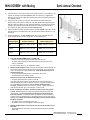
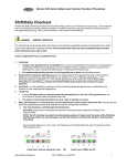
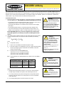
Figure 1. MINI-SCREEN trip test
Verify that the MINI-SCREEN System is in RUN mode
• Green and yellow Light Screen and System status indicators ON.
• The green Light Screen indicator will flash if blanking is programmed. Ensure
muting is not enabled.
See user’s manual, Section 5.1 for Key Reset procedure.
b)
With the guarded machine at rest, slowly pass the test piece downward through the
defined area at three points, perpendicular to the defined area: close to the receiver,
close to the emitter, and midway between them. Verify that while the test piece is
within the defined area:
• The red Light Screen status indicator comes ON and remains ON
• The green System status indicator is OFF
Remove the test piece from the defined area and verify:
• The green Light Screen status indicator comes ON
If the green Light Screen indicator comes ON at any time when the test piece is
within the defined area, check for reflective surfaces, or unguarded areas created by
use of fixed blanking (see Warnings). Do not continue until the situation is
corrected. (See Manual Sections 3.2.2 and 3.2.4.) Perform a System Key Reset to
reset the latch after each pass of the test piece, on latch models.
c)
Ensure that muting is not enabled, and initiate machine motion of the guarded
machine. While the machine is moving, insert the test piece into the defined area
(perpendicular to it). Do not attempt to insert the test piece into the dangerous
parts of the machine. As the test piece enters the defined area at any time during
machine motion, the dangerous parts of the machine should come to a stop with no
apparent delay. Remove the test piece from the defined area and perform a System
Key Reset. Verify that:
• The machine does not automatically restart, and
• The initiation devices must be engaged to restart the machine
d)
With the guarded machine at rest, insert the test piece into the defined area and
verify that:
• The guarded machine cannot be put into motion while the test piece is within the
defined area.
page 2
Banner Engineering Corp. • Minneapolis, U.S.A.
www.bannerengineering.com • Tel: 763.544.3164