1
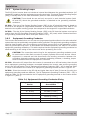
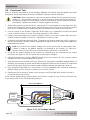
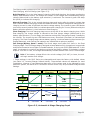
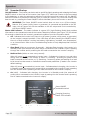
Installation 2.4.1 DC Wire Sizing It is important to use the correct DC wire to achieve maximum efficiency from the system and reduce fire hazards associated with overheating. Always keep your wire runs as short as practical to help prevent low voltage shutdowns and keep the DC breaker from nuisance tripping (or open fuses) because of increased current draw. See Table 2-1 to select the required minimum DC wire size (and corresponding overcurrent device) based on your inverter model. The cable sizes listed in Table 2-1 for your inverter model are required to reduce stress on the inverter, minimize voltage drops, increase system efficiency, and ensure the inverter’s ability to surge heavy loads. If the distance from the inverter to the battery bank is greater than 5 feet (1.5 m), the DC wire size will need to be increased. Longer distances cause an increase in resistance, which affects the performance of the inverter. Continue to use the overcurrent device previously determined from Table 2-1, and then refer to Table 2-2 to determine the minimum DC wire size needed for various distances based on your inverter model. 2.4.2 DC Overcurrent Protection DC overcurrent protection is not included in the inverter, it must be provided as part of the installation. This requirement is needed in order to comply with electrical code regulations and for safety reasons. The DC overcurrent protection device must be installed in the positive DC cable line, it can be a fuse or a circuit breaker, and it must be DC rated. It must be correctly sized according to the size of DC cables being used, which means it is required to open before the cable reaches its maximum current carrying capability, thereby preventing a fire. The NEC requires both overcurrent protection and a disconnect switch. If a circuit breaker is used as the overcurrent protection device, it can also be used as the required DC disconnect. If a fuse is used as an overcurrent device, a Class-T type or equivalent is recommended. This fuse type is rated for DC operation, can handle the high short-circuit currents, and has a time delay that allows for momentary current surges from the inverter without opening the fuse. However, because the fuse can be energized from both directions, if it is accessible to unqualified persons the NEC requires that it be installed in such a manner that the power must be disconnected on both ends of the fuse before servicing. The recommendations in Table 2-1 may not meet all local code requirements. Table 2-1, Recommended DC Wire/Overcurrent Device for Rated Use Using Conduit DC Grounding Electrode Wire Size4 Inverter Model Maximum Continuous Current1 RD2624E 173 amps #4/0 AWG [107.2 mm2] (260 amps) 250 amps #6 AWG (13.3 mm2) RD4024E 267 amps #4/0 AWG [107.2 mm2] (260 amps) 250 amps #6 AWG (13.3 mm2) Minimum DC Wire Size (90°C rating)2 Maximum DC Breaker Size3 Note 1 - Maximum Continuous Current is based on the inverter’s continuous power rating at the lowest input voltage with an inefficiency factor. Note 2 - Wire size is based on the requirements needed to increase efficiency and reduce stress to the inverter. Note 3 - The next larger standard size overcurrent device may be used if the de-rated cable ampacity falls between the standard recommended overcurrent devices. Note 4 - As recommended, the DC grounding electrode conductor can be a #6 AWG (33.6 mm2) conductor if that is the only connection to the grounding electrode and that grounding electrode is a rod, pipe, or plate electrode. Note 5 - May not allow continuous operation at full rated power. Page 15 © 2010 Magnum Energy, Inc