1
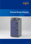
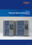
ESPEC offers a compact, but high performance
thermal shock chamber ideal for the requirements of
test standards of small and low-volume specimen.
Equipped with superior temperature recovery performance
capable of answering the requirements of severe test specifications,
this thermal shock model offers a wide test area in a compact, slim design.
1
User-friendly
A high performance compact package to meet severe test
requirements.
A temperature recovery time
of less than 5 minutes is
achieved in 2 zones (+150℃
and −65℃) without auxiliary
cooling.
By realizing a temperature recovery time
of less than 5 minutes for the upstream air
in the 2 zones (+150℃ and −65℃), we
have achieved performance equivalent to
that of a large thermal shock chamber
without having to use auxiliary cooling by
means of liquid carbon dioxide, which
was required in previous compact thermal
shock chamber.
Complies with MIL-STD-883E
and other test standards.
This compact thermal shock chamber
satisfies the temperature cycle test
requirements of MIL-STD-883E and
other test standard (see page 5).
High-temperature exposure
Examples of temperature uniformity
Test conditions
High temperature exposure +150℃ 30 min
Low temperature exposure −65℃ 30 min
Specimen
Plastic molded IC 2kg
●
Vibration shock to samples is
minimized during
movement of the test area.
The soft-move mode is used to reduce
vibration shock when moving from the
high-temperature chamber specimens
are to the low-temperature chamber in
the test area.
Low-temperature exposure
●Temperature uniformity measurement method
Thermocouples were embedded in 10 plastic
molded ICs (16 pin DIPs), which were then
placed on two levels in each of the corners and
in the center of a specimen basket.
Temperature of the sensor
Within ±1.5℃ (Test area: upstream)
Uniform temperature
distribution across specimens.
High temperature uniformity performance
ensures consistent stress on specimens.
Within ±1.0℃
2
Utility
Uses a color LCD interactive
touch-screen system employed
throughout the Thermal Shock
Chamber Series.
A color LCD panel design is employed
that allows easy settings by just touching
the screen in accordance with the display.
The test pattern, test area temperature,
number of temperature cycles, upstream/
downstream control, trend graph display
are all displayed on the visible screen.
Large 10.9-liter-capacity test area
Control panel
Instrument specification
Setting
Interactive key input by touch panel
Display
TFT Color LCD
Number of test
RAM (selected entry): a maximum of 20 patterns can be entered
patterns
ROM (built-in): contains 10 test standard patterns
Auxiliary
functions
・ Test continuity selection
・ Overheat/overcool protection
・ Stable time control
・ Automatic defrost
・ Test halt preset
・ Automatic power shut-off
・ Trend graph display
・ Time signal
・ RS-485
● Test
・ Timer preset
・ Sensor traceability
・ Power failure/recovery operation selection
・ Programmed time display
・ Test completion mode selection
・ Exposure time reduction
・ Alarm history display
・ Program memory
A mechanism to prevent
specimen from dropping.
In addition to the drive unit brake, there is
other protection mechanism to prevent
specimens from dropping in the test area
when the chamber stops operation.
Easy wiring for applying power
or measuring specimens.
A cable port is provided on the side to
allow easy wiring of specimens for
measurement during high and lowtemperature cycle tests.
area
23
0m
m
148mm
320m
m
Features a 10.9-liter test area, twice that
of our previous model. The volume that
can be processed is greatly increased, and
a 210×297mm printed circuit board can
be tested in the horizontal position.
Total safety measures.
Test area drive is automatically halted
when door is opened, and it is automatically locked during operation. Other
redundant safety mechanisms are also
used to ensure user safety.
Equipped with casters for mobility
Cable port
(50mm, shown with cap installed)
3
Eco-friendly
Incorporates many features for environmental protection
(energy conservation, recycling, ozone layer protection)
Small footprint
● Required footprint
2
(Installation space: 2.88 m )
Top view
Unit: mm
600
Rear intake and
ceiling exhaust
1050
Reduced power consumption is an
important issue for our customers. This
compact thermal shock chamber
employs number of measures such as
refrigeration capacity variable control
by electronic auto-expansion valve and
the use of a titanium interior material
aimed specifically at energy savings.
2250
Reduced power consumption
Material indication for recycling
Various environmental protection
measures have been taken such as
indicating materials on plastic molded
parts and employing a structure that makes
it easy to remove recyclable parts to
accommodate future recycling of the unit.
600
Vertical design saves space. Required
installation space is only 26 inch.
300
680
300
1280
Uses HFC to protect the global
environment
The refrigerant used for the refrigerator is
an HFC which causes no damage to the
ozone layer, and thus complies with the
measures for ozone layer protection
specified by the Montreal Protocol.
Paperless Recording (optional)
The paperless recorder makes it easy
record the temperatures of different
components, such as the chamber
temperature, on a memory card (Compact
Flash).
Paperless recorder (optional) *Sample photo
4
TEST STANDARD (TSE-11-A compliant)
Exposure temperature
Test standard
High temp
A
B
MIL-STD-883E
(Method No. C
1010.7)
D
F
JIS C 0025
10
0
+15
+125℃
0
+15
+150℃
0
+15
+200℃
0
+15
+175℃
0
+ 70℃ ±2
+ 85℃ ±2
+100℃ ±2
Ambient
+125℃ ±2
temp
+155℃ ±2
+175℃ ±2
+200℃ ±2
85
+
+
℃
1
+
85℃
JASO D 001 2
+
75℃
3
+
EIAJ ED-2531A
Ambient temp*
Ambient
temp
Low temp
55
60℃ ±2
65℃ ±2
70℃ ±2
75℃ ±2 Ambient
80℃ ±2 temp
85℃ ±2
90℃ ±2
95℃ ±2
100℃ ±2
0
10
− ℃
−
65
0
10
− ℃
−
more than
10 min
Specimen
temp within
15 min.
at worst
condition
Number of
cycles
Minimum
10 cycles
5
Low or high
temp
5℃ ±3
3 hours
10℃ ±3
2 hours
less than 10% 5 cycles if not
25℃ ±3
1 hour
0.5 hour less than 10 sec of exposure
specified Low temp
40℃ ±3
time
3
hours
55℃ ±3
65℃ ±3 if not specified
40℃
−
Less than 0.2 kg
1 hour +150 min
0.2∼0.8 kg
Short
Upstream of
2 hours +150 min
exposure is specimen
0.8∼1.5 kg recommendable
within 5 min.
3 hours +150 min
More than 1.5 kg
4 hours +150 min
6 cycles
High temp
0℃ ±3
5℃ ±3
10℃ ±3
3 hours
15℃ ±3
2 hours
than 10%
20℃ ±3
1 hour less than 10 sec less
of exposure 5 or 10 cycles Low temp
25℃ ±3
0.5
hour
time
30℃ ±3
hours
35℃ ±3 if not3specified
40℃ ±3
45℃ ±3
50℃ ±3
−
−
−
−
−
−
−
−
−
−
The noted specification tests include only those tests applicable to TSE-11-A. For further information, please contact us.
* Ambient temperature at exposure temperature and exposure time represent the temperature and time when moving from high temperature chamber to
low temperature chamber.
■
Test starting
point
−
−
−
−
−
−
120℃
+
+
+
+
+
+
+
+
+
Exposure time
Temp
High/ low temp Ambient temp* recovery time
SPECIFICATIONS
Model
TSE-11-A
Performance*3
Temperature recovery Low temp chamber High temp chamber Test area
performance
System
Operation temperature
High temp. exposure range
Low temp. exposure range
Temperature fluctuation*1
Pre-heat upper limit
2-zone system by means of vertical movement of specimen
0∼+40℃ (+32 to +104。F)
+60∼+200℃ (+140 to +392。
F)
−65∼0℃ (−85 to +32。
F)
±0.5℃ (±0.9。
F)
200℃ (+392。F)
+
Temp. heat-up rate*2
Within 30 min from ambient temp. to +200℃ (+392。F)
Pre-cool lower limit
Temp. pull-down rate*2
Recovery conditions
Refrigerator unit
Construction
Recovery time
Outer shell
Interior
Insulation
Heater
Cooler
Air circulator
Refrigeration sytem
Compressor
Refrigerant
Condenser
Components
Test area load capacity
Specimen basket load capacity
Inside dimensions (W×H×D)
Outside dimensions (W×H×D)*4
Weight
Power supply
(Power supply deviation: rating ±10%)
Full load current
Exhaust heat quantity*3
Noise
80℃ (−112。F)
−
Within 90 min from ambient temp. to −80℃ (−112。F)
・ 2 zones
。
High temperature exposure : +150℃ (+302
F), 30min
Low temperature exposure : −65℃ (−85。F), 30 min
・ Sensor position : Upstream of specimen
・ Specimens: plastic molded IC 2kg
within 5 min
Painted steel
18-8 Cr-Ni stainless steel plate (SUS 304), titanium plate
Glass wool, foamed polyurethane
Stripped wire heater
Plate fin cooler, cold accumulator
Sirocco fan
Mechanical cascade refrigeration system
Rotary 1.5 kW
R508A R404A
Air-cooled condenser
Cable port (1pc, inside diameter 50mm, on right side of chamber), Specimen power supply
control terminal, Time signal (2), Integrating hour meter without reset, power cord
8kg
2kg (equally distributed load)
320×148×230mm (12.6×5.8×9 in)
680×1625×1050mm (26.8×64×41.3 in)
approximately 390kg
200V AC 3φ 3W
220V AC 3φ 3W 380V AC 3φ 4W 400/415V AC 3φ
50/60Hz
60Hz
50Hz
4W 50Hz (EU spec.)
26A
25A
17A
17A
17,585kJ/h
60dB or less
(At 1m from front of chamber, 1.2m from floor. (A-characteristic) depending on environment)
*1 Performance indicators conform to JTM K01-1998 of Japan Testing Machinery Association.
*2 Temperature heat-up/pull-down rate imply performance of each temperature chamber.
*3 At ambient temperature +23℃.
*4 Excluding protrusions.
●Do not use specimens which are explosive or inflammable, or which contain such
substances. To do so could be hazardous, as this may lead to fire or explosion.
DANGER
●Do
not
place
corrosive
materials
in
the
chamber.
If
corrosive
substances
or
humidifying water is used, the life of the unit may be significantly shortened.
●Do not place life forms or substances that exceed allowable heat generation.
Be sure to read the instruction manual before operation.
CAUTION
6
SAFETY DEVICES
●
●
●
●
●
●
●
●
●
●
●
●
●
●
●
●
●
●
●
●
●
●
OPTIONS
Leakage breaker (200, 220, 380, 400/ 415V AC)
Circuit breaker (400V AC)
Electric parts compartment door switch
Temperature switch for overheat protection of high-temperature chamber
Temperature switch for overheat protection of low-temperature chamber
Overheat protector for high-temp. chamber (Built-in controller)
Overheat/ overcool protectors for low temp. chamber. (Built-in controller)
Test area overheat and overcool protectors (Built-in controller)
Test area overheat / overcool protectors
Refrigerator high pressure switch
Thermal relay for compressor
Compressor temperature switch
Air circulator temperature switch
Thermal relay for air circulator
Motor inverter
Motor reverse prevention relay
High-temperature chamber door switch
Low-temperature chamber door switch
Test area hold
Door lock mechanism
Fuse
Specimen power supply control terminal
Paperless recorder
Records temperature inside the
chamber. Additional inputs may also
be recorded
Number of inputs:
PL1S: 1 (5 more but turned OFF*)
Data saving cycle: 1 sec
PL3S: 3 (3 more but turned OFF*)
Data saving cycle: 1 sec
PL3L: 3 (3 more but turned OFF*)
Data saving cycle: 5 sec
Temperature range: −100℃ to +220℃
External recording media :
CF memory card (32 MB)
* Settings may be modified.
Paperless recorder
ACCESSORIES
●
●
●
●
●
Specimen basket (stainless steel, 5 mesh screen)
W320×H35×D230mm
Withstand load: 2kg (equally distributed)
Fuse (glass tube 5 A)
Rubber plug
Wirefisher
User's manual
Temperature recorder (digital)
2
1each
2
1
1
−100 to +220℃/100mm
RK-61: 1pen
RK-63: 3 pens
RK-64: 6 dots
Temperature recorder
Temperature recorder for
future installation
Preparation of a power cable, temperature sensor, and a grounding wire
for additional installation in the future.
7
OPTIONS
Terminal for recorder
External alarm terminal
Specimen basket
Serves to output temperature within
test area, high temp chamber, low temp
chamber.
If the safety device of the chamber
activates, the external alarm terminal
will notify the alarm to distant place.
Equivalent to standard accessory.
・Material: stainless steel (5 mesh)
Emergency stop switch
Stops the chamber immediately.
Terminal for recorder
Specimen basket
Thermocouple
Fixture for securing body
Thermocouple measures the temperature
of specimens.
・T JIS C 1602 with ball attached
Emergency stop switch
Total cycle counter
Power cord
Indicates cycle counts.
・Display range: 1~99999999
(with resetting function)
Used to connect to the primary
power source.
・5, 10m
Auxiliary cooling injector (LCO2)
Used to reduce the temperature
recovery time of low temperature
exposure by injecting liquefied carbon
dioxide at beginning of exposure.
Used to bolt the chamber to the
floor.
Color specifications
Auxiliary cooling injector (LN2)
Chamber can be painted to a desired
color according to a color sample.
Used to reduce the temperature
recovery time of low temperature
exposure by injecting liquefied
nitrogen at beginning of exposure.
Extra overheat protector
Additional preventive measures can
be taken for excessive temperature
rise in the chamber, in addition to the
standard double equipped overheat
protector.
Communication functions
Cable port rubber plug
Prevents air leakage from the cable
port.
Computer interface
・GP−IB
・RS−232C
・E−BUS
*Select one other than standard RS−485.
Communication cable
・RS−485 5, 10m
・GP−IB 2, 4m
・RS−232C 1.5, 3, 5m
1.5, 3, 5m for extension
・E−BUS 5, 10m
Additional overheat
protector
■Some photographs listed in this catalog contain Japanese display.
8