1
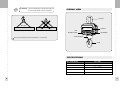
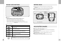
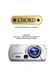
Crane Scale
CASTON
OWNER’S MANUAL (BT Ver.)
9007-CT3-BT33-0
2006. 07
CONTENTS
PRECAUTIONS
OVERALL VIEW
SPECIFICATIONS
DISPLAY & KEY FUNCTIONS
BATTERY USAGE
USE OF BATTERY CHARGER
FUNCTIONS & DESCRIPTIONS
TEST MODE
SET MODE
COMMUNICATION MODE
COMMAND PROTOCOL(ASCLL CODE)
BAUDRATE
DATA FORMAT
PRODUCT NO.(ID) & COUNTER
OPTIONS
PRODUCT SIZE
ERROR MESSAGE
4
7
7
8
9
9
10
11
12
13
15
15
16
17
19
20
22
PRECAUTIONS
Turn power switch off on rear panel when you don't use the scale for
a long time.
Do not stand under the scale while weighing the load, and you
should be careful to provide against a safety accident.
To install, safety pin in hook should be fixed to prevent dropping out
from lift eye bolt.
Attention
Warning
Do not disassemble the scale.
When any damage or
defect occurs, contact
your CAS authorized
dealer immediately for
proper repair.
Do not overload beyond the maximum
weight limit.
Scale must be grounded to minimize
electricity static. This will minimize
defect or electric shock.
For consistent and accurate reading,
maintain periodical check by your
CAS authorized dealer.
Avoid sudden shock to the scale.
Internal mechanism could be damaged.
Do not pull the plug by its cord when
unplugging. Damaged cord could cause
electric shock or fire.
To prevent from fire occurring, Do not
place or use the scale near
flammable or corrosive
gas.
To reduce electric shock or incorrect
reading, Do not spill water on the scale
or place it in humid condition.
Place the scale on firm and temperature
consistent environment.
Keep the scale away from other
electromagnetic generating devices.
This may interfere with accurate
reading.
Avoid placing the scale near heater
or in direct sunlight.
Use proper Adapter. Incorrect adapter
could damage the scale.
Insert plug firmly to wall outlet to
prevent electric shock.
4
Take the battery out when scale is not in
use for long time. Leakage from the
batteries is hazardous.
5
WARNING
WARNING : The load which hang on the hook should be
a vertical load. (Refer to the next features)
OVERALL VIEW
LIFT EYE
DISPLAY
LOAD
LOAD
LOW
BATTERY LAMP
KEYBOARD
LOAD HOUSING
The load which hang on the hook should be a vertical load.
HOOK
SPECIFICATIONS
MAX. TARE WEIGHT
DISPLAY
OPERATION TEMPERATURE
POWER SOURCE
POWER CONSUMPTION
DISPLAY LAMP
6
FULL TARE
L.E.D(1.5 inch)
10
40
DC 12 V Rechargeble Battery / AC Adaptor
1.2 ~ 2.4W
ZERO, TARE, HOLD, LOW BATTERY LAMP
7
DISPLAY & KEY FUNCTIONS
BATTERY USAGE
Open the battery lid located in back of the scale and turn main
switch off.
Separate the battery connector and take out the discharged battery.
Put a charged battery in rear and connect the battery connector.
Turn main power switch on and cover the battery lid.
MAX 5000 kg
MIN. : 200 kg
e = d = 2 kg
LATCH
BATTERY
CONNECTOP
BATTERY
BOLT
POWER S/W
BATTERY
DISPLAY
FUSE
WEIGHT DISPLAY:Displays weight or messages (5 Digit).
ZERO LAMP:Indicates that scale is stable and at zero.
NET LAMP:Indicates that scale is currently using a tare.
HOLD LAMP:Indicates that the HOLD function is activated.
LOW BATTERY LAMP:Indicates that voltage of battery low and should be
changed soon.
FIG 1. CLOSE STATE
FIG 2. OPEN STATE
KEY FUNCTIONS
KEYS
8
FUNCTIONS
OFF
Used to turn the scale ON / OFF or used to released from
TEST/SET mode
ZERO
Used to reset the scale zero
TARE
Used to activate tare function and to clear tare entry
HOLD
HOLD
Used to weigh unstable things (livestock, liquid, etc.) or used to
store the set value in SET mode
SET
Used to check the current AD value and the voltage of battery in
TEST mode
WARNING
WARNING:Do not press the keys with excessive
force, the keys are be pressed with a soft touch.
USE OF BATTERY CHARGER
Check the voltage of battery charger before use.
(It is fixed to 220V before shipping)
Insert charger A.C cord into the power source and connect the discharged
battery to the connector.
Turn ON the switch on the battery charger, charging will start wiht RED lamp
(CHARGE) turn on.
When the charging is completed, GREEN lamp(FULL) turns on.
Estimated time for charging is 15 hours.
(Charging time can be varying according to the battery condition.)
9
FUNCTIONS & DESCRIPTIONS
Press the ON key located in real panel of the scale.
(While the power is off, the ON/OFF key on the remote control wouldn't
operate.)
Press ON/ OFF key for 0.5 second
LED display will be on and then, it will show from 00000 to 99999 continuously
(In the case of BlueTooth model, the LED display will show up the above
message after checking wireless connections between the scale and the remote
contoller)
2. POWER OFF
5. HOLD FUNCTION
There are tow HOLD functions : Average Hold function, Peak Hold function
Average Hold
- Press the HOLD key while weighing an unstable item
- The averaged value of the weight fluctuation will be displayed after few seconds.
Peak Hold
- Press the HOLD key while weighing an unstable item.
Release of Hold Functions
- Press the HOLD key while HOLD functions are activated
- hdoFF will display and then, the scale return to normal weighing mode.
Press ON/OFF key for 2 seconds
LED display will show off message and then power turns off
TEST MODE
3. ZERO FUNCTION
Used to correct drifted zero nalue when the scale is unloaded motion is not
detected
(You can adjust the zero up to 10% of the maximum capacity
The function does not work when weight is fluctuated ort unstable.
4. TARE FUNCTION
Use tare function after removing the weighing material from container being used.
The function does not work when weight is fluctuated ort unstable.
The weight including TARE weight can't exceed the maximum capacity.
Press *key for 1 second after power on, then the scale
enter into TEST mode.
Key Usage
* KEY
Used to display the AD value and the voltage of battery
(1.A/D value Display,
2. Voltage of battery)
Other KEY
Used reyurn the normal weighing mode.
Voltage of battery indication
1
It will display the current voltage down to two places of decimals
2
It will display battery error Er-04 when the voltage of battery is under 10.8V
(The scale is automatically power off when the voltage of battery is under 10.5V
10
11
SET MODE
Communication Type
(Count)
Press TARE key and press ON key while TARE key is pressed, then
you can enter into SET mode.
Key Usage
Used to increase the input value
TARE KEY
Used to decrease the input value
HOLD KEY
Used to memorize the input value
When you press HOLD key for 1 second after saving the input value
ON/OFF KEY
Used to move the next menu without saving the input value
When you press ON/OFF key for 1 second then, you can go to the
next mode
Bluetooth 2 Module
7
-
BT1 : Print Output
Command Mode
Command Mode Type
1
0
Stream (about 1 sec period)
Stable
1)F1,2 is not showed in SET mode of RF type, zero operation time is set
always as 1 sec.
2)Command mode in F9 is always works regardless of RF mode or
Bluetooth mode.
COMMUNICATION MODE
RANGE
DEFAULT
VALUE
F 0 Speed control of weight
1~23
10
1 : fast,
F 1 Zero operation time set
0~9
5
0.5~2.3 sec (Step:0.2)
F 2 Automatic zero range set
0~9
5
0~4.5 digit (Step:0.5)
F 3 Stable interval set
0~9
5
0.5~1.5 sec (Step:0.1)
F 4 Stable range set
0~9
5
0~4.5 digit (Step:0.5)
F 5 Hold type set
0,1
0
0 : Average, 1 : Peak
F 6 LED display On / Off
0,1
0
1 : Off
-
Producct ID can be stored
F 7 Weight Backup
0,1
0
1 : Backup
-
1
-
Bluetooth 1 Module
Functions of CASTON- B can be controlled by PC command such as reading
weight data, time and etc.
2
-
Bluetooth 2 Module
3
-
BT1 : Print Output
NO
F8
12
6
2
Setting Menu
Bluetooth 1 Module
-
0
F9
ZERO KEY
5
FUNCTION
Communication Type
(Product No.)
DESCRIPTION
23 : slow
CASTON BT have 6 communication modes ; RS-232C(RF), Bluetooth
1 channel, and Bluetooth 2 channel equipped with product NO.
function or counter function.
F8 Communication type
-
ID Number ( 0:232(RF), 1 :BT1, 2 :BT2)
-
Counter
( 4:232(RF), 5 :BT1, 6 :BT2)
Function
13
Available module combination (Adjustable in function set F8)
Bluetooth 1 module (F8 : 1, 5)
1)
CASTON -
B + PC (232C BT Module)
2)
CASTON -
B + TW-100 B (1set) + PC (RS - 232C)
Bluetooth 2 module (F8 : 2, 6)
Bluetooth 1 module (F8 : 1, 5)
1) Type
CASTON -
B + TW-100 B(2set) + PC (RS - 232C)
2)Function
CASTON -
B + PC(232C BT Module 2)
2)Function
Functions of CASTON- B can be controlled by PC command such
as reading weight data, time and sending product ID, weight data,
time and etc.
RS - 232C(RF) module (F8:0,4)
RS - 232C (RF) module (F8:0,4)
1) Type
CASTON-
B + PC (RS - 232C RF module)
Command protocol (ASCLL CODE)
-ENQ W (05h 57h)
Weight Data Command (Display)
-ENQ G (05h 47h)
Gross Data Demand (same as W command format)
-ENQ N (05h 4eh)
Net Data Demand (same as W command format)
-ENQ Z (05h 5ah)
Zero set
-ENQ T (05h 54h)
Tare set
-ENQ F (05h 46h)
Display On/Off(toggle)
-ENQ E (05h 45h)
Error Clear
-ENQ H (05h 48h)
Hold On/Off (toggle)
-ENQ S (05h 53h)
Sum (accumulate the current weight data when the
scale received this command)
-ENQ C (05h 43h)
Sum Clear
-ENQ D (05h 44h)
Sum Weight Data Demand (same as W command format)
-ENQ P (05h 50h)
Print(It uses the TW - 100 and it prints)
-ENQ p (05h 70h)
Print (CASTON-
-ENQ y (05h 79h)
Time set
-ENQ Y (05h 59h)
Asking for time data
-ENQ V (05h 56h)
Asking for battery voltage
sends a data with the printer rightly)
BAUDRATE
Bluetooth Module
RF(Japan) Module
14
-9600bps
-1200bps
15
Period
DATA FORMAT
The scale will reply to W , G , N , D Command in below data format.
Weight Format (14 Bytes)
Data
Transfer
A
C
I
I
I
I
W
W
W
W
W
P
S
B
C
O
D
D
D
D
1
2
3
4
5
E
T
C
K
M
1
2
3
4
R
A
C
4
X
0
Example
6
0
0
1
2
0
2
1
6
2
1
H
1) Number
2) COM
No decimal point
0 31
1st place of decimal point
0 32
2nd place of decimal point
0 33
3rd place of decimal point
0 34
4th place of decimal point
If error is occurred, then the scale transmit error code as below Error table
Error
2
X
BIT
D7
D6
H
H
Description Over Memory
Product No.
Weight Data
D3
D2
D1
D0
Bt2
Bt1
Battery
Zero
Load
Cell
Calib
ration
Product No.(ID) & Counter
From COM to STA , Exclusive OR value
In the case of Japan RF module, Dummy Code is transmitted
additionally before this weight format data
These modes are common in all kinds of module in the scale.
Choosing ID mode or Count Mode is done in Set Mode.
Product No.(ID)
- Product No.(ID) is allowed to input in 4 digit.
- If BCC is correct then the scale transmit ACK(06H), otherwise it sends NAK(15H)
- BCC : Exclusive OR value from ID 1 to 4
Dummy Code(Hex) : 55 55 55 55 55 55 55 55 55 55 55 a6
12 e0(14byte)
(Dummy Code is an typical character of codule)
SPECC
D7
D6
D5
D4
D3
D2
D1
D0
CONTENTS
0
+/-
Error
Hold
+/-
Tare
Stable
Zero
ACTIVE
1
-
Error
Hold
-
Tare
Stable
Zero
D6(+/-) : Gloss +/D3(+/-) : Display +/-
ID Format(6 Bytes)
CONTENT
Status
16
D4
W or D or G or N Command Char
4) W
BIT
D5
Each number is travsmitted in ASCII type string
3) ID
5) BCC
0 30
Data Transfer
ENQ
ID1
ID2
ID3
ID4
BCC
Example
05H
0
0
1
3
XXH
Counter
- It shows the number of times of counted weight.
(When the weight goes to 0kg and the weight is stable, then counter is increasing)
- When the power turns on, the number of count is initialized as zero
17
Time Setting Command
OPTIONS
ENQ Y (05h, 79h) : Time Data
SPECC
Please refer to handy terminal TW-100 B manual of CASTONBluetooth Type)
Time Set Format (15 bytes)
B(Crane Scale :
CONTENT
Data
Transfer
E
y
N
Y
Y
M
M
D
D
H
H
m
M
S
S
B
1
2
1
2
1
2
1
2
1
2
1
2
C
Q
0
Example
C
7
5
9
H
H
X
0
4
0
5
1
5
1
2
0
0
0
0
X
H
Number : Each number is transmitted in ASCII type string
If BCC is correct then the scale transmit ACK(06H), otherwise it sends NAK(15H)
BCC : Exclusive OR value from y to S2(Operator should input the value)
ENQ Y (05h, 59h) : Time Data
SPECC
Data
Transfer
Example
Time Demand Format(14 bytes)
Frequency
2400~2483.5 MHz
Channel interval
1 Mhz
Channel
78 channel
Communication Type
A
Y
Y
M
M
D
D
H
H
m
M
S
S
B
C
1
2
1
2
1
2
1
2
1
2
1
2
C
Communication Speed
Actual Communication
Distance
Display
K
C
0
X
Size of letter
X
Display below zero
H
Battery life time
6
0
4
0
5
Fig.2 Charger
1. TW-100 Specification
Time Data Demand Command
CONTENT
Fig.1 TW-100
1
5
1
2
H
0
0
0
0
Battery charging time
Number : Each number is transmitted in ASCII type string
BCC : Exclusive OR value from Y1 to S2
Power
GFSK(Gaussina Frequency Shift Keying)
9600
Maximum. Approximately 50~100M
LCD (5 digit)
12 mm (Height)
- displayed
Approx. 6 hours
Approx. 3~5 hours
TW -100 : Rechargeable DC Battery7.2V750mA
Charger : AC220V/60Hz
Power consumption
Temperature range
Function
18
0.43~0.72 W
-10
~ +40
Printer interface, zero, tare, hold, print,
ID setting, weight sum, peak hold.
19
10 TON 50 TON
PRODUCT SIZE
0.5 TON 5 TON
(UNIT: mm)
20
MODEL
MAX.CAPA
DIVISION
A
WEIGHT
0.5THD
0.5TON
200g
510
26kg
MODEL
1THD
1TON
500g
510
26kg
10THD
10TON
2THD
2TON
1kg
515
28kg
15THD
15TON
3THD
3TON
2kg
515
28kg
20THD
20TON
5THD
5TON
2kg
538
31kg
30THD
50THD
(UNIT: mm)
MAX.CAPA DIVISION
A
B
5kg
667
360
10kg
682
360
10kg
725
360
30TON
20kg
895
50TON
20kg
1400
C
D
E
F
G
WEIGHT
83
845
57.2
42
57.2
44kg
99
886
63.5
50
63.5
53kg
126 990
86
60
86
76kg
440
138 1200
108
92
108
220kg
440
180 1520
146
112.7
146
390kg
21
ERROR MESSAGE
ovEr
Contents
Above the maximum allowable weight reading.
Remark
Check weighed material.
Er - 01
Contents
Calibration problem.
Remark
Perform Calibration.
Er - 02
Contents
Load cell connection failure or error in A/D conversion part.
Remark
Check L/C connection & test A/D conversion test.
Er - 03
Contents
Zero value exceed 10 & of zero range.
Remark
Check conditions of L/C and Hook.
Er - 06
Contents
Error in bluetooth module 2
Remark
Check condition of BT2
Er - 07
Contents
Failure in internal memory.
Remark
Whole configuration is necessary.
An error which is not removed before clearing the cause of the error
ovEr, Er - 02, Er - 04.
Zero value exceed 10 & of zero range.
An error which will be removed automatically after showing error message
Er - 03
An error which can be removed by deleting error message command \
Er - 01, Er - 05, Er - 06, Er - 07
Removal of Error Message
Deleting error message command is works when On/Off key is pressed or
error delete command in command mode from PC.
Er - 04
Contents
Warning of low voltage of battery (Approximately under 10.8V).
Remark
If below 10.4V, caston is shut down.
Er - 05
Contents
Error in bluetooth module 1.
Remark
Check condition of BT1.
22
23
MEM0
24
MEM0
25
MEM0
26