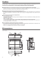
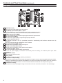
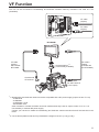
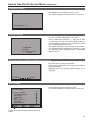
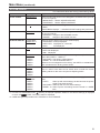
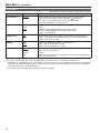
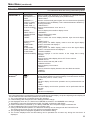
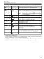
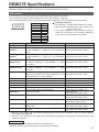
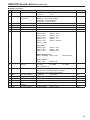
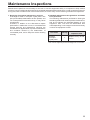
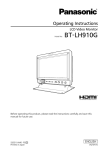
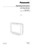
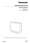
1
Operating Instructions
LCD Video Monitor
Model No.
Model No.
BT-LH80WP
BT-LH80WE
Before operating this product, please read the instructions carefully and save this manual for
future use.
S0507N0 -M
Printed in Japan
ENGLISH
VQT1H75
Read this first! (For BT-LH80WP)
CAUTION
RISK OF ELECTRIC SHOCK
DO NOT OPEN
CAUTION: TO REDUCE THE RISK OF ELECTRIC SHOCK,
DO NOT REMOVE COVER (OR BACK).
NO USER SERVICEABLE PARTS INSIDE.
REFER TO SERVICING TO QUALIFIED SERVICE
PERSONNEL.
The lightning flash with arrowhead
symbol, within an equilateral
triangle, is intended to alert the
user to the presence of uninsulated
“dangerous voltage” within the
product’s enclosure that may be of
sufficient magnitude to constitute a
risk of electric shock to persons.
The exclamation point within an
equilateral triangle is intended
to alert the user to the presence
of
important
operating
and
maintenance (service) instructions
in the literature accompanying the
appliance.
WARNING:
• TO REDUCE THE RISK OF FIRE OR
SHOCK HAZARD, DO NOT EXPOSE THIS
EQUIPMENT TO RAIN OR MOISTURE.
• TO REDUCE THE RISK OF FIRE
OR SHOCK HAZARD, KEEP THIS
EQUIPMENT AWAY FROM ALL LIQUIDS.
USE AND STORE ONLY IN LOCATIONS
WHICH ARE NOT EXPOSED TO THE
RISK OF DRIPPING OR SPLASHING
LIQUIDS, AND DO NOT PLACE ANY
LIQUID CONTAINERS ON TOP OF THE
EQUIPMENT.
CAUTION:
TO REDUCE THE RISK OF FIRE OR
SHOCK
HAZARD AND ANNOYING
INTERFERENCE,
USE
THE
RECOMMENDED ACCESSORIES ONLY.
FCC Note:
This equipment has been tested and
found to comply with the limits for a class
A digital device, pursuant to Part 15 of the
FCC Rules. These limits are designed
to provide reasonable protection against
harmful interference when the equipment is
operated in a commercial environment. This
equipment generates, uses, and can radiate
radio frequency energy, and if not installed
and used in accordance with the instruction
manual, may cause harmful interference
to radio communications. Operation of this
equipment in a residential area is likely to
cause harmful interference in which case the
user will be required to correct the interference
at his own expense.
Warning:
To assure continued FCC emission limit
compliance, the user must use only shielded
interface cables when connecting to external units.
Also, any unauthorized changes or modifications
to this equipment could void the user’s authority
to operate it.
Notice (U.S.A. only):
This product has a fluorescent lamp that
contains mercury. Disposal may be regulated
in your community due to environmental
considerations. For disposal or recycling
information, please contact your local
authorities, or the Electronics Industries
Alliance:
<http://www.eiae.org>
CAUTION:
In order to maintain adequate ventilation, do
not install or place this unit in a bookcase,
built-in cabinet or any other confined space.
To prevent risk of electric shock or fire hazard
due to overheating, ensure that curtains
and any other materials do not obstruct the
ventilation.
CAUTION:
• Keep the temperature inside the rack to
between 5 °C to 40 °C (41 °F to 104 °F).
• Bolt the rack securely to the floor so that it
will not topple over.
indicates safety information.
A rechargeable battery that is recyclable powers the product you have purchased.
2
Read this first! (For BT-LH80WE)
DO NOT REMOVE PANEL COVERS BY
UNSCREWING THEM.
To reduce the risk of electric shock, do not
remove the covers. No user serviceable parts
inside.
Refer servicing to qualified service
personnel.
WARNING:
• TO REDUCE THE RISK OF FIRE OR
SHOCK HAZARD, DO NOT EXPOSE THIS
EQUIPMENT TO RAIN OR MOISTURE.
• TO REDUCE THE RISK OF FIRE
OR SHOCK HAZARD, KEEP THIS
EQUIPMENT AWAY FROM ALL LIQUIDS.
USE AND STORE ONLY IN LOCATIONS
WHICH ARE NOT EXPOSED TO THE
RISK OF DRIPPING OR SPLASHING
LIQUIDS, AND DO NOT PLACE ANY
LIQUID CONTAINERS ON TOP OF THE
EQUIPMENT.
CAUTION:
In order to maintain adequate ventilation, do
not install or place this unit in a bookcase,
built-in cabinet or any other confined space.
To prevent risk of electric shock or fire hazard
due to overheating, ensure that curtains
and any other materials do not obstruct the
ventilation.
CAUTION:
• Keep the temperature inside the rack to
between 5 °C to 40 °C.
• Bolt the rack securely to the floor so that it
will not topple over.
CAUTION:
TO REDUCE THE RISK OF FIRE OR
SHOCK
HAZARD AND ANNOYING
INTERFERENCE,
USE
THE
RECOMMENDED ACCESSORIES ONLY.
indicates safety information.
Attention/Attentie
ENGLISH
• Battery is used for the main power source in the product.
At the end of their useful life, you should not throw them away.
Instead, hand them in as small chemical waste.
NEDERLANDS
• Voor de primaire voeding van het apparaat wordt gebruikgemaakt van een
batterij.
Wanneer de batterij is uitgeput, mag u deze niet gewoon weggooien, maar dient u deze als klein
chemisch afval weg te doen.
TO REMOVE THE BATTERY
Main Power Battery (Ni-Cd / Ni-MH / Li-ion Battery)
• To detach the battery, please proceed in the reverse order of the installation method described in this
manual.
• If a battery made by any other manufacturer is to be used, check the Operating Instructions
accompanying the battery.
3
Contents
Read this first! (For BT-LH80WP) . . . . . . . . . . . . . . . 2
Read this first! (For BT-LH80WE) . . . . . . . . . . . . . . . 3
Standard accessory . . . . . . . . . . . . . . . . . . . . . . . . . 4
Optional unit . . . . . . . . . . . . . . . . . . . . . . . . . . . . . . . 4
Precautions for use . . . . . . . . . . . . . . . . . . . . . . . . . . 5
Outline . . . . . . . . . . . . . . . . . . . . . . . . . . . . . . . . . . . . 6
Dimensions . . . . . . . . . . . . . . . . . . . . . . . . . . . . . . . . 6
Controls and Their Functions . . . . . . . . . . . . . . . . . 7
Front panel . . . . . . . . . . . . . . . . . . . . . . . . . . . . . . . . 7
Rear panel . . . . . . . . . . . . . . . . . . . . . . . . . . . . . . . . 8
Supplying the power . . . . . . . . . . . . . . . . . . . . . . . . . 9
Using the Anton/Bauer type battery pack. . . . . . . . . 9
Using a V-mount type battery pack . . . . . . . . . . . . . 9
Using an external DC power supply. . . . . . . . . . . . 10
VF Function . . . . . . . . . . . . . . . . . . . . . . . . . . . . . . . 11
How to Use the On Screen Menu . . . . . . . . . . . . . . 12
Operating status display . . . . . . . . . . . . . . . . . . . . 12
Picture adjusting knob status . . . . . . . . . . . . . . . . . 12
Sharpness display . . . . . . . . . . . . . . . . . . . . . . . . . 13
Function display . . . . . . . . . . . . . . . . . . . . . . . . . . . 13
DC power supply voltage and battery level display 13
Menu display . . . . . . . . . . . . . . . . . . . . . . . . . . . . . 13
Menu operations . . . . . . . . . . . . . . . . . . . . . . . . . . 14
User Data . . . . . . . . . . . . . . . . . . . . . . . . . . . . . . . . . 15
Saving user data . . . . . . . . . . . . . . . . . . . . . . . . . . 15
Loading user data . . . . . . . . . . . . . . . . . . . . . . . . . 15
Main Menu . . . . . . . . . . . . . . . . . . . . . . . . . . . . . . . . 16
Menu configuration . . . . . . . . . . . . . . . . . . . . . . . . 16
MARKER . . . . . . . . . . . . . . . . . . . . . . . . . . . . . . . . 17
Types of MARKER . . . . . . . . . . . . . . . . . . . . . . . . . 18
VIDEO CONFIG . . . . . . . . . . . . . . . . . . . . . . . . . . . 19
SYSTEM CONFIG . . . . . . . . . . . . . . . . . . . . . . . . . 21
VF CONFIG . . . . . . . . . . . . . . . . . . . . . . . . . . . . . . 22
FUNCTION . . . . . . . . . . . . . . . . . . . . . . . . . . . . . . 23
GPI . . . . . . . . . . . . . . . . . . . . . . . . . . . . . . . . . . . . . 28
INPUT SELECT . . . . . . . . . . . . . . . . . . . . . . . . . . . 29
CONTROL . . . . . . . . . . . . . . . . . . . . . . . . . . . . . . . 30
HOURMETER . . . . . . . . . . . . . . . . . . . . . . . . . . . . 30
REMOTE Specifications . . . . . . . . . . . . . . . . . . . . . 31
GPI terminal . . . . . . . . . . . . . . . . . . . . . . . . . . . . . . 31
RS-232C terminal . . . . . . . . . . . . . . . . . . . . . . . . . 32
RS-232C REMOTE operation method . . . . . . . . . . 32
Maintenance Inspections . . . . . . . . . . . . . . . . . . . . 35
Error/Warning Displays . . . . . . . . . . . . . . . . . . . . . . 36
Maintenance . . . . . . . . . . . . . . . . . . . . . . . . . . . . . . . 36
Specifications . . . . . . . . . . . . . . . . . . . . . . . . . . . . . 36
Standard accessory
• Battery mount terminal block [2 screws (M3 x 4) included] × 1
• Screw spacer (already installed on the unit) × 1
Optional unit
• SDI input unit BT-YA80G
• VF Cable Set BT-CS80G
(DC cable also included → page 11)
4
Precautions for use
This product has been specially designed for commercial use. As such, it should be used and operated
only by persons with related expertise.
The liquid crystal parts are fabricated using high-precision technology. The screen has effective pixels
that cover more than 99.99% of its area, but pixels may be missing or remain permanently lighted (red,
blue and/or green) in less than 0.01% of the area. This is not indicative of malfunctioning.
The panel which protects the liquid crystal display has been specially treated.
Do not wipe it with hard cloths or rub it heavily as this will damage the surface of the panel.
If a still image is displayed continuously for a long period of time, the image may be burnt onto the
screen for some time.
(The shadow of the image will usually disappear after moving images are displayed for while.)
The response speed and brightness of the liquid crystals will vary with the surrounding temperature.
Do not expose the liquid crystal display to strong light, as it could cause a deterioration in the display
characteristics and reduce the display quality.
Do not keep in an environment where the temperature changes suddenly, because condensation could
form on the surface of the liquid crystal or in the internal parts and cause a reduction in the display
quality or a malfunction.
Screen irregularities may be generated when certain images are displayed.
If the unit is left for a long time in a location with a high temperature or humidity, it could change the
characteristics of the liquid crystal panel and cause irregularities.
5
Outline
The BT-LH80W is a thin and lightweight liquid crystal monitor designed especially for broadcasting service and
business use. It is equipped with a 7.9-inch V (effective display area) liquid crystal display panel.
It can be used as a VF (viewfinder) for broadcasting and business cameras made by Panasonic.
Equipped with a new IP conversion circuit, the circuit processing greatly reduces time delays
A new I/P conversion circuit has been introduced that converts and generates SD and HD interlace signals to
high-precision progressive signals without generating time delays per field.
Equipped with a diagonal line correction processing circuit
By detecting correlations in the field in the diagonal direction in addition to the vertical direction, the unit performs
the optimum interpolation to minimize the rough noise occurring in the diagonal direction and create a smooth
image.
New functions that support focus adjustments
• FOCUS-IN-RED function
The section of the image that is being focused is displayed in an easy-to-understand red, making camera focus
adjustments very easy.
• PIXEL TO PIXEL function
The input signal is displayed without being resized, greatly facilitating camera focus adjustments.
If you are not resizing the image, you can check the image by expanding a 1080/60i signal to the equivalent of
an image approximately 19 inches wide.
Thin, lightweight, compact and low energy consumption
The unit has a compact body that makes the most of the thin and lightweight characteristics of LCD panels, with
a depth of 64.7 mm (2-9/16 inches) and a weight of 1.5 kg (3.3 lb).
Further, it is compatible with HD and has low energy consumption.
Dimensions
Unit: mm (inches)
20.2
(13/16)
C
UN
-16
3/8
44 (1-3/4)
3/816U
NC
64.7 (2-9/16)
218 (8-9/16)
52 (2-1/16)
218 (8-9/16)
176 (6-15/16)
13 (1/2)
1.5 (1/16)
C
UN
16
8/
3
6
20.2
(13/16)
3/
816
UN
C
49 (1-15/16)
136 (5-3/8)
166 (6-9/16)
M3
26.5 (1-1/16)
44 (1-3/4)
100 (3-15/16)
93 (3-11/16)
166 (6-9/16)
M3
Controls and Their Functions
Front panel
5
POWER
1
FUNCTION
2
1
2
3
4
5
6
2
3
FOCUS-R
3
ENTER
INPUT MENU
1
6
PEAK/
PHASE
CHROMA
BRIGHT
CONT/
B.LIGHT
4
POWER switch/lamp
This switches the power supply ON/OFF. When the power is ON, the LED (green) lights up.
INPUT SELECT button
This selects the signal input line. Each time the button is pressed, the input changes in the following order:
YPBPR → VF-YPBPR/VF-VIDEO → VIDEO → SDI.
YPBPR
: Analog component input
VF-YPBPR / VF-VIDEO∗1 : Viewfinder input
VIDEO
: Video input
SDI∗2
: Serial digital interface input (compatible with HD/SD)
• The input line when the power supply is switched ON is the one that was selected the last time the power was
switched OFF. The INPUT menu settings can be used to skip input lines that are not used.
• When the control lock is on, input lines cannot be selected.
∗1 The menu is used to set either YPBPR or VIDEO for the viewfinder input.
∗2 Can only be selected when the separately sold BT-YA80G is installed.
MENU and FUNCTION buttons
These are used for menu display, selecting settings and adjustments, and for carrying out the items selected in
the menu.
MENU
: Push to display or exit the menu, or to return to the previous menu screen.
/ FUNCTION1
: Push to move the cursor down and select an item.
In addition, FUNCTION1 carries out the item selected in the menu.
/ FUNCTION2
: Push to move the cursor up and select an item.
In addition, FUNCTION2 carries out the item selected in the menu.
ENTER / FUNCTION3 : Push to confirm a setting, or to display a submenu.
In addition, FUNCTION3 carries out the item selected in the menu.
• When the control lock is on, the key mark appears and FUNCTION operations cannot be executed.
Picture adjusting knobs/lamps
PEAK [PEAKING] 0 - 30(0) / PHASE 0 - 60(30)
CHROMA 0 - 60(30) / FOCUS-R(→page 27) 0 - 30(25)
BRIGHT 0 - 60(30)
CONT [CONTRAST] 0 - 60(50) / B.LIGHT [BACKLIGHT] 0 - 60(60) ( ) denotes factory preset values
A rotating knob that can be pushed to operate. When the picture adjusting knob is pressed, its status is displayed
and adjustment becomes possible. The setting values are saved by pushing the knob again.
When values are changed from the factory preset values, the LEDs to the side of knobs (amber) light.
The setting values are loaded when the monitor’s power is switched ON. The setting values are saved when the
knob is pushed, or when 10 seconds pass after changing the settings. However, operating changes cannot be
made in the following cases.
• When the control lock is on, the key mark appears and setting values cannot be changed.
• Only items selected in the menu can be adjusted for PEAK/PHASE and CONT/B. LIGHT.
• When the MONO function is ON, PHASE and CHROMA operations are disabled.
• FOCUS-R is enabled during operations of the FOCUS-IN-RED function.
• During BLUE ONLY, the PEAK/PHASE knob functions as PHASE.
R-TALLY (red)
Can be lit by a control signal from a GPI/camera.
G-TALLY (green)
Can be lit by a control signal from a GPI/camera.
7
Controls and Their Functions (continued)
Rear panel
7
17
8 9
SDI
(OPTION)
7
VIDEO/
Y
PR
10
PB
VF
GPI
11
RS-232C
12
13
DC IN
18
7
8
9
10
11
12
13
14
15
16
17
18
8
16
15
17
14
18
REAR TALLY (red)
Can be lit by a control signal from a GPI/camera.
SDI (HD/SD) input terminal (BNC) - option
This is the SDI input terminal. (Compatible with HD/SD automatic switching)
• If you want this input, contact the vendor where you purchased the unit.
VIDEO/Y input terminal (BNC)
This is the VIDEO signal (component signal) input terminal/Y input terminal.
PBPR input terminal (BNC)
This is the PBPR signal (analog component signal) input terminal.
VF terminal (D-SUB, 15 pins)
This terminal connects to the VF (viewfinder) terminal of broadcasting and business cameras made by
Panasonic.
The unit can be used as the viewfinder for such a camera.
GPI input terminal (D-SUB, 9 pins)
External control is possible by using a GPI signal.
RS-232C terminal (D-SUB, 9 pins)
External control is possible by using an RS-232C interface.
DC IN terminal (XLR, 4 pins)
This is the external DC power supply input terminal.
When a DC power supply is connected concurrently with the battery, the external power input takes
precedence.
Light control switch
This is not used on this monitor.
Battery holder
This holder is used with a battery made by Anton/Bauer.
Screw holes for tripod fixing
There are two screw holes on both the top and bottom for fixing the unit to a tripod (compatible with 3/8-16UNC).
In addition, removable screw spacers are installed in one of the screw holes on the bottom of the unit, which are
compatible with 1/4-20UNC screws. Use the size that matches the diameter of the tripod’s fixing screw.
Screw holes for fixing
There are four screw holes (M3) for fixing the mounter on the rear of the unit, two each on the left and right.
Supplying the power
An Anton/Bauer or V-mount type of battery pack or an external DC power supply can be used to power this
monitor.
Using the Anton/Bauer type battery pack
1.
Using a V-mount type battery pack
Install the Anton/Bauer type of battery pack.
CAUTION:
These servicing instructions are for use by qualified
service personnel only. To reduce the risk of electric
shock, do not perform any servicing other than that
contained in the operating instructions unless you
are qualified to do so.
Battery pack
1.
2.
Remove the battery holder.
Battery holder
Insert the battery pack and slide it in the direction
of the arrow.
Release
lever
2.
Install the accessory battery mount terminal block.
<Reference>
To remove the battery pack, slide it in the opposite
direction to the one in which it was attached while
keeping the release lever on the battery holder pulled
down all the way.
Battery mount terminal
block
3.
Fix the V-mount type battery holder with four screws
(length 8 mm (5/16 inch)) supplied with the holder,
and then fasten the two screws on the terminal
section.
This connector
is not used.
V-mount type
battery holder
9
Supplying the power (continued)
Using an external DC power supply
1.
Connect the external DC power supply to the DC IN
socket on this unit.
DC IN socket
4
3
DC IN socket
2
1: GND
4: +12 V
1
External DC power supply
2.
Turn “ON” the external DC power supply switch.
(Where the external DC power supply has a power
switch)
3.
Turn “ON” the POWER switch on this unit.
If an external DC power supply is used, then check the
ratings of the external DC power supply so that they
are compatible with those of this unit.
Check the pin arrangements of the DC output terminal
of the external DC power supply and those of the DC
IN socket of this unit so that their polarities are
correctly arranged.
If +12 V are supplied to the unit’s GND terminal by
mistake, this may cause fire or injury.
10
<Notes>
• Use a shield cable with a length of 2 m (6.56 feet) or
less for the DC cable. Use of cords any longer than
2 m (6.56 feet) may result in noise appearing on the
screen.
• If the battery pack and an external DC power supply
are connected simultaneously, then the external DC
power supply will have priority.
If the external DC power supply is used, then the
battery pack may be fitted or removed.
• If an external DC power supply is used, then make
sure that the external DC power supply is first turned
ON, then this unit is turned ON. If they are turned ON
in the reverse order, then this unit may malfunction,
because the output voltage of the external DC power
supply will gradually increase.
• Input voltage that above the specification is not
displayed accurately.
VF Function
The unit can be connected to broadcasting and business cameras made by Panasonic and used as a VF
(viewfinder).
VF cable
(Option)
DC cable
(Option)
BT-LH80W
VF cable
(Option)
Part number:
BT-CS80G
Camera platform ∗2
(commercially available)
Camera side
VF terminal
DC cable∗1
(Option.
Included with
the BT-CS80G.)
Camera side
DC OUT terminal
(1.5 A output)
∗1 Broadcasting and business camera-recorders compatible with a DC power supply (output current of 1.5 A)
AJ-HDC27H
AJ-HDX900
AJ-HPX2000 / 2100
AG-HPX500 / 502
Other cameras or camera-recorders cannot be used because they have an output current of 1 A or 0.1 A.
Use a battery or external DC power supply.
Contact your vendor for details of broadcasting and business camera-recorders that will be launched in the
future.
∗2 Use a camera platform that can fully withstand the weight of the unit (1.5 kg (3.3 lb)).
11
How to Use the On Screen Menu
Six types of information are displayed on the screen: the operating status display, picture adjusting knob status,
sharpness display, function display, DC power supply voltage display, battery level display and menu display.
Operating status display
1
7
6
2
YPBPR 1080/60I
P-P
DC14.0V
5 4
50%
3
1. The selected input line (→ page 7, 2 )
• YPBPR, VF-YPBPR/VF-VIDEO, VIDEO, SDI
2. Signal format
• The display status can be set in “STATUS DISPLAY”
in the “SYSTEM CONFIG” menu (→ page 21).
• If “UNSUPPORT SIGNAL” is displayed, then either
the current input signal is not supported or the “INPUT
SELECT” menu setting needs to be changed.
• When “NO SIGNAL” is displayed, there is no input
signal.
3. Battery level display
• When an Anton/Bauer type digital battery is used,
battery level is displayed using a block count ( )
and percentage.
4. Various displays (PIXEL TO PIXEL mode)
• Displayed when the picture display is PIXEL TO
PIXEL.
5. Various displays (warning of improper operation
status for the camera settings)
• Displayed when there is an improper operation
status relative to the camera settings.
6. DC power supply voltage display
• DC power supply voltage is displayed.
7. Various displays (lock setting)
• Displayed when front operations are locked
(→ page 30).
<Note>
“UNSUPPORT SIGNAL” and “NO SIGNAL” may not be
displayed correctly.
Picture adjusting knob status
[PHASE]
32
Picture adjusting knob (→ page 7, 4 )
• This knob can be rotated and pushed.
• The status display appears when the knob is pushed.
The display disappears when the knob is pushed
again, or if the knob is not operated for 10 seconds.
• The settings can be adjusted while this display is
shown, but the settings cannot be adjusted after the
display disappears.
Status display:
PEAKING or PHASE
CHROMA or FOCUS-IN-RED
BRIGHT
CONTRAST or BACKLIGHT
12
How to Use the On Screen Menu (continued)
Sharpness display
• SHARPNESS H/V is displayed when it is set.
• The display disappears if remains idle for 2 minutes.
SHARPNESS H 30
Function display
F1:MARKER
F2:WFM
F3:PIXEL TO PIXEL
XXXXX
• You can set FUNCTION display in the menu.
• When “FUNCTION DISPLAY” (→ page 23) is ON1
or ON2 and one of the buttons from [FUNCTION1] to
[FUNCTION3] is pressed, the unit displays the status
of the FUNCTION item that is set.
• The display disappears if remains idle for 2 seconds.
• The operational status is displayed in “XXXXX” (→ page
24 “Operation status displayed when a FUNCTION
button is used”).
DC power supply voltage and battery level display
• DC power supply voltage is displayed.
• Battery level is displayed when using an Anton/Bauer
type digital battery.
• Displayed when the operating status display is not
displayed.
DC14.0V
50%
Menu display
[MAIN MENU]
MARKER
VIDEO CONFIG
SYSTEM CONFIG
VF CONFIG
FUNCTION
GPI
INPUT SELECT
CONTROL
HOURMETER
MENU EXIT
• This is displayed when the menu is used.
• The display disappears if remains idle for 2 minutes.
SEL. ENTER ENTER
Displays the operation explanation for the menu
button.
13
How to Use the On Screen Menu (continued)
Menu operations
1. Push [MENU] to display the MAIN menu.
] to select the sub menu, then push
3. Push [ ,
[ENTER].
The setting values in the sub menu change to
green.
FUNCTION
1
INPUT
2. Push [ ,
[ENTER].
MENU
2
3
ENTER
] to select the menu, then push
[MAIN MENU]
MARKER
VIDEO CONFIG
SYSTEM CONFIG
VF CONFIG
FUNCTION
GPI
INPUT SELECT
CONTROL
HOURMETER
MENU EXIT
SEL. ENTER ENTER
To return to the previous screen
Push [MENU].
14
[MARKER]
OFF
MARKER
OFF
16:9
OFF
4:3
BACK
NORMAL
CENTER
OFF
GPI PRESET1
4:3
GPI PRESET2
4:3
MENU EXIT
SEL. ENTER SET
4. Push [ ,
] to select the setting values, then
push [ENTER].
Push [MENU] to cancel.
[MARKER]
ON
MARKER
OFF
16:9
OFF
4:3
BACK
NORMAL
MARKER
OFF
GPI PRESET1
4:3
GPI PRESET2
4:3
MENU EXIT
SEL. ENTER SET
User Data
You can change the menu setting values and picture adjusting knob settings, then save and load up to 5 combinations
of screen adjustment values as user data. You can also return the setting values and adjustment values to the
factory preset settings.
The following settings are included in user data.
• Menu settings except for “SETUP LOAD/SAVE” and “REMOTE of CONTROL” (including the button function
settings on the front of the monitor)
• Screen adjustment values changed in picture adjusting knob
Saving user data
Loading user data
1. Push [MENU] to display the MAIN menu.
2. Push [ ,
] to select the “SYSTEM CONFIG”
menu and push [ENTER].
3. Push [ ,
] to select the “SETUP SAVE” sub
menu and push [ENTER].
The setting values in the sub menu change to
green.
[SYSTEM CONFIG]
CONT./BACK.
BACKLIGHT
PEAKING/PHASE
STATUS DISPLAY
BATTERY REMAIN
SETUP LOAD
SETUP SAVE
PWR ON SETUP
BACKLIGHT
-PEAKING
3SEC OFF
OFF
FACTORY
USER1
LAST
SEL. ENTER ENTER
MENU EXIT
1. Push [MENU] to display the MAIN menu.
] to select the “SYSTEM CONFIG”
2. Push [ ,
menu and push [ENTER].
3. Push [ ,
] to select the “SETUP LOAD” sub
menu and push [ENTER].
The setting values in the sub menu change to
green.
[SYSTEM CONFIG]
CONT./BACK.
BACKLIGHT
PEAKING/PHASE
STATUS DISPLAY
BATTERY REMAIN
SETUP LOAD
SETUP SAVE
PWR ON SETUP
SEL. ENTER ENTER
MENU EXIT
Changes to green
4. Push [ , ] to select the file you wish to save to
from “USER1” – “USER5”, then push [ENTER].
The following screen appears.
BACKLIGHT
-PEAKING
3SEC OFF
OFF
FACTORY
USER1
LAST
Changes to green
] to select the file you wish to load to
4. Push [ ,
from “USER1” – “USER5”, then push [ENTER].
The following screen appears.
To return to the factory preset setting values, select
“FACTORY”.
[SETUP SAVE]
USER1
YES
NO
MENU EXIT
[SETUP LOAD]
USER1
YES
NO
SEL. ENTER SET
5. Select “YES”, and push [ENTER].
The user data is saved.
MENU EXIT
SEL. ENTER SET
5. Select “YES”, and push [ENTER].
The user data is loaded.
To return to the previous screen
Push [MENU].
15
Main Menu
Menu configuration
MAIN MENU
MARKER
MARKER
16:9
VIDEO CONFIG
SYSTEM CONFIG
COLOR TEMP.
4:3
CONT./BACK.
SHARPNESS MODE
BACK
BACKLIGHT
SHARPNESS H
CENTER
PEAKING/PHASE
SHARPNESS V
GPI PRESET1
STATUS DISPLAY
I-P MODE
GPI PRESET2
BATTERY REMAIN
MONO
SETUP LOAD
SD ASPECT
D93
SETUP SAVE
D65
PWR ON SETUP
VF CONFIG
USER 63
D56
VF CONTROL
VAR1
[WHITE BALANCE VAR1]*
CROSS HATCH
VAR2
[WHITE BALANCE VAR2]*
REAR TALLY
VAR3
[WHITE BALANCE VAR3]*
ZEBRA
RETURN CH
FUNCTION
FUNCTION1
COLOR TEMP.
FUNCTION2
GAIN RED
FUNCTION3
GAIN GREEN
FUNCTION DISPLAY
GAIN BLUE
*[WHITE BALANCE VAR1-3]
BIAS RED
BIAS GREEN
BIAS BLUE
RESET
GPI
INPUT SELECT
GPI CONTROL
YPBPR
ON
COMPONENT LEVEL
VF
ON
VIDEO/YPBPR
SIGNAL TYPE
VIDEO
ON
FORMAT
NTSC SETUP
SDI
CONTROL
HOURMETER
16
ON
CONTROL
LOCAL ENABLE
OPERATION
LCD
GPI1
GPI2
GPI3
GPI4
GPI5
GPI6
GPI7
GPI8
Main Menu (continued)
MARKER
The underlined values are factory preset setting values.
Sub menu
MARKER
Settings
OFF∗1
ON
Explanation
Used to make MARKER settings effective.
16:9∗2∗3
OFF
4:3
13:9
14:9
CNSCO
VISTA
95%
93%
90%
88%
80%
Used to select/display the type of marker when the aspect ratio setting
is 16:9.
<OFF>
Marker not displayed.
<4:3>
4:3 marker
<13:9>
13:9 marker
<14:9>
14:9 marker
<CNSCO> CNSCO marker
<VISTA> VISTA marker
<95%>
95% Area marker
<93%>
93% Area marker <90%>
90% Area marker
<88%>
88% Area marker <80%>
80% Area marker
4:3∗2
OFF
95%
93%
90%
88%
80%
Used to select/display the type of 4:3 marker.
<OFF> Marker not displayed.
<95%> 95% Area marker
<93%> 93% Area marker
<90%> 90% Area marker
<88%> 88% Area marker
<80%> 80% Area marker
BACK∗2
NORMAL
HALF
BLACK
Used to select the background brightness excluding the marker.
<NORMAL> Normal background
<HALF>
Background brightness 50%
<BLACK> Background brightness 0% (Black)
CENTER∗2
OFF
ON
Used to display the center marker.
<OFF>
Not displayed
<ON>
Displayed
GPI PRESET1∗4
4:3
13:9
14:9
CNSCO
VISTA
95% (16:9)
93% (16:9)
90% (16:9)
88% (16:9)
80% (16:9)
95% (4:3)
93% (4:3)
90% (4:3)
88% (4:3)
80% (4:3)
GPI PRESET1: Used to select the marker to be displayed using the
GPI terminal “MARKER1 ON/OFF” operation (→ page 31).
GPI PRESET2: Used to select the marker to be displayed using the
GPI terminal “MARKER2 ON/OFF” operation (→ page 31).
<4:3>
4:3 marker
<13:9>
13:9 marker
<14:9>
14:9 marker
<CNSCO> CNSCO marker
<VISTA>
VISTA marker
<95% (16:9)> 95% Area marker when the aspect ratio is 16:9.
<93% (16:9)> 93% Area marker when the aspect ratio is 16:9.
<90% (16:9)> 90% Area marker when the aspect ratio is 16:9.
<88% (16:9)> 88% Area marker when the aspect ratio is 16:9.
<80% (16:9)> 80% Area marker when the aspect ratio is 16:9.
<95% (4:3)> 95% Area marker when the aspect ratio is 4:3.
<93% (4:3)> 93% Area marker when the aspect ratio is 4:3.
<90% (4:3)> 90% Area marker when the aspect ratio is 4:3.
<88% (4:3)> 88% Area marker when the aspect ratio is 4:3.
<80% (4:3)> 80% Area marker when the aspect ratio is 4:3.
GPI PRESET2∗4
• The marker is not displayed during VF line operation.
• The marker display size is the display size of a camera-recorder, and so is smaller than the previous model (BTLH900A).
∗1 The setting becomes “ON” when the unit receives marker-related control during REMOTE operation. (Priority
goes to GPI when GPI settings exist.)
∗2 When controlling the marker settings using the GPI function (→ page 31), these settings become disabled.
∗3 These are only enabled when the HD signal and SD signal aspect ratio settings are 16:9.
∗4 When the HD signal and SD signal aspect ratio setting is 16:9, a 4:3 marker is displayed in the center 4:3
area.
17
Main Menu (continued)
Types of MARKER
16:9 marker
(Displayed when using HD, or when using SD
with a 16:9 aspect ratio)
The marker is only displayed as a vertical bar. In
section becomes the “MARKER
addition, the
BACK” item.
4:3 marker
4:3 marker
(Displayed when using SD with a 4:3 aspect ratio)
A dotted line is displayed as the marker.
95% Area marker
93% Area marker
90% Area marker
88% Area marker
13:9 marker
14:9 marker
VISTA marker, CNSCO marker
A horizontal dotted line is displayed as the marker.
80% Area marker
(Displayed when using HD, or when using SD
with a 16:9 aspect ratio)
A dotted line is displayed as the marker.
VISTA marker
CNSCO marker
Area marker
A dotted line is displayed as the marker.
95% Area marker
90% Area marker
80% Area marker
95% Area marker
93% Area marker
90% Area marker
88% Area marker
93% Area marker
88% Area marker
80% Area marker
∗ You can display 4:3 marker at the same time as
16:9 marker.
Simultaneously display example
The
section becomes the “MARKER BACK” item. The
background selected with the 16:9 marker is controlled.
16:9 marker:
95% Area marker
80% Area marker 4:3 marker:
80% Area marker
95% Area marker
Center marker
Center marker
The marker is displayed in
the center of the picture.
18
Main Menu (continued)
VIDEO CONFIG
The underlined values are factory preset setting values.
Sub menu
Settings
Explanation
COLOR TEMP.
USER 63∗1
D93
D65
D56
VAR1
VAR2
VAR3
Used to select the color temperature.
<USER 0 - 63>Adjustable settings 0 - 63
(color temperature around 3000K - 9300K)
<D93>
Color temperature around 9300K
<D65>
Color temperature around 6500K
<D56>
Color temperature around 5600K
<VAR1>
WB adjustment mode∗2
<VAR2>
WB adjustment mode∗2
<VAR3>
WB adjustment mode∗2
SHARPNESS
MODE
HIGH∗3
LOW
Used to select the width of the sharpness edge.
<HIGH> Thin edge
<LOW> Thick edge
SHARPNESS H
0 - 30∗3
Used to set the sharpness in the horizontal direction.
When adjusting, the item display moves to the lower part of the
screen.
SHARPNESS V
0 - 30∗3
Used to set the sharpness in the vertical direction.
When adjusting, the item display moves to the lower part of the
screen.
I-P MODE
MODE2
MODE1
Used to select IP conversion mode. (→ page 20 “About IP Mode”)
<MODE2> Field Interpolation
<MODE1> Frame Interpolation
MONO∗4
OFF
ON
Used to switch between color and monochrome (MONO).
<OFF> Color
<ON> Monochrome
∗ When this is ON, the picture adjusting knob [CHROMA] setting is
fixed at 0.
SD ASPECT∗4
4:3
16:9
Used for setting the aspect ratio settings when using SD signal
input.
<4:3> 4:3 display
<16:9> 16:9 display
∗1 When selecting USER 0 - 63
], and push [ENTER].
1) Push [ENTER] (USER changes to blue).
2) Select 0 - 63 with [ ,
∗2 When “VAR1”, “VAR2” or “VAR3” is selected, the monitor switches to WB adjustment mode (→ page 20).
∗3 The following sharpness values can each be set,
1) VIDEO system input line (VIDEO)(Factory settings are SHARPNESS MODE: LOW, SHARPNESS H/V: 0)
2) any other input line’s HD (Factory settings are SHARPNESS MODE: HIGH, SHARPNESS H/V: 0)
3) any other input line’s SD (Factory settings are SHARPNESS MODE: LOW, SHARPNESS H/V: 0)
and the setting values for the selected input signal from within this group is displayed. The adjustment status is
displayed in the bottom right when selected.
∗4 During GPI control, the setting items are displayed in gray and the display changes in accordance with the GPI
control.
19
Main Menu (continued)
About IP Mode
By selecting “MODE1”, you can convert IP through Frame Interpolation.
This unit has reduced the Frame Interpolation delay to 1 field or less, compared to our old models having caused
1 frame delay or more.
Factory preset setting value is “MODE1” recommended for normal use. Depending on images, in very rare
cases, noise may occur on the screen. In such a case, “MODE 2” is recommended.
By selecting “MODE2”, you can convert IP through Field Interpolation.
Since MODE2 interpolates only within each Field, it is suitable to confirm interlace condition.
Depending on still images, etc., flickers may occur on the screen. In such a case, “MODE1” is recommended.
WB adjustment mode
You can adjust “WHITE BALANCE VAR1” - “WHITE BALANCE VAR3” (WB) by selecting “VAR1” - “VAR3” in
“COLOR TEMP.” in the “VIDEO CONFIG” menu.
The underlined values are factory preset setting values.
Explanation
Sub menu
Settings
COLOR TEMP.∗1
USER 0 - 63
D93
D65
D56
Used to select the color temperature that will become the
basis for adjustments.
<USER 0 - 63>Adjustable settings 0 - 63
(color temperature around 3000K - 9300K)
<D93>
Color temperature around 9300K
<D65>
Color temperature around 6500K
<D56>
Color temperature around 5600K
GAIN RED
0 - 511
(Factory presets
are values for color
temperature <D65>.)
∗ The presets are
values adjusted
before shipment from
factories.
GAIN elements for RED are adjusted.∗2
–512 - 511
(Factory preset settings:
0)
BIAS elements for RED are adjusted.∗2
GAIN GREEN
GAIN BLUE
BIAS RED
BIAS GREEN
BIAS BLUE
RESET
GAIN elements for GREEN are adjusted.∗2
GAIN elements for BLUE are adjusted.∗2
BIAS elements for GREEN are adjusted.∗2
BIAS elements for BLUE are adjusted.∗2
“GAIN RED” - “BIAS BLUE” values are reset to color temperatures
values selected in “COLOR TEMP.”.
∗1 When “COLOR TEMP.” is selected and [ENTER] is pressed following item change, the display changes to the
confirmation screen. Selecting “YES” and pressing [ENTER] on this screen return GAIN and BIAS values to the
selected color temperature values.
∗2 When adjusting, the item display moves to the lower part of the screen.
20
Main Menu (continued)
SYSTEM CONFIG
The underlined values are factory preset setting values.
Sub menu
Settings
Explanation
CONT. /BACK.
BACKLIGHT
CONTRAST
Used to select the function to be assigned to CONT/B.LIGHT (a knob
on the front panel).
<BACKLIGHT> Used to adjust BACKLIGHT.
<CONTRAST> Used to adjust CONTRAST.
BACKLIGHT
0 - 60
Used to adjust the LCD backlight level.
<Note>
CONT./BACK displays “-” while BACKLIGHT settings are performed.
PEAKING/PHASE
PEAKING
PHASE
Used to select the function to be assigned to PEAK/PHASE (a knob
on the front panel).
<PEAKING> Assigns to the PEAKING function.
<PHASE>
Assigns to the PHASE function.
STATUS DISPLAY
CONTINUE
3SEC OFF∗1
OFF
Used to set the display time for the status display.
<CONTINUE> Always displayed.
<3SEC OFF> Displayed for 3 seconds.
<OFF>
Not displayed.
BATTERY REMAIN
OFF
ON
Used to select whether or not to display the battery level.
<OFF> Not displayed.
<ON> Displayed.
SETUP LOAD
FACTORY
USER1
USER2
USER3
USER4
USER5
Used to load the saved factory preset setting values (FACTORY) or
user data (USER 1 - USER 5).
<FACTORY> The factory preset settings.
<USER1 - 5> The saved USER data ∗2.
When the unit is shipped from the factory, the USER 1 to 5 data items
are the same as the factory preset values.
SETUP SAVE
USER1
USER2
USER3
USER4
USER5
Used to save user data.
Up to 5 sets of user data can be saved, which include the current
setting values for the menu and picture adjusting knobs.
PWR ON SETUP
LAST
FACTORY
USER1
USER2
USER3
USER4
USER5
Used to select the settings for when the power supply is switched
ON.
<LAST>
Starts up with same settings as the last time the power
supply was switched OFF.
<FACTORY> Starts up with the FACTORY settings.
<USER1 - 5> Starts up with the settings that are saved in a USER
item.
∗1 Functions as CONTINUE when
(warning of improper operation status for the camera settings) is displayed
or when the P-P (PIXEL TO PIXEL) status is displayed.
∗2 USER saving is not possible when CONTROL is set to REMOTE.
21
Main Menu (continued)
VF CONFIG
The underlined values are factory preset setting values.
Sub menu
Settings
Explanation
VF CONTROL
VF-CH
ALL-CH
Used to select the input line for the VF function of the monitor.
(VF function: tally lamp lit, zebra displayed,
displayed)
<VF-CH> Only enabled when the VF line is selected.
<ALL-CH> Enabled with all input lines.
CROSS HATCH
HIGH
LOW
OFF
Used to set whether to display a cross hatch and select its density
level.
<HIGH> 70/256 (displays with a dense cross hatch)
<LOW> 20/256 (displays with a light cross hatch)
<OFF> Not displayed.
REAR TALLY
ON
OFF
Used to allow control of the tally lamp on the rear of the monitor.
<ON> Lamp lights when TALLY control from a GPI/camera is ON.
<OFF> Lamp does not light.
ZEBRA
ON
OFF
Used to set ZEBRA information in the camera.
<ON> Sets the information to ON.
<OFF> Sets the information to OFF.
RETURN CH∗1∗2
YPBPR
VF
VIDEO
SDI
Used to select the signal input line by operating the RETURN (RET)
button of the camera lens.
<Note>
When there is no SDI input unit (option), the SDI item is displayed in
gray and cannot be set.
• The priority sequence for GPI control and RS-232C is as follows: GPI > VF CONFIG > RS-232C.
∗1 RETURN CH operates when VF CONTROL is set to ALL-CH. It is not affected by the various line ON/OFF
settings in the INPUT SELECT menu (→ page 29). (Input lines that are set with RETURN CH are enabled even
if they are set to OFF in INPUT SELECT.)
∗2 A function to be used with future Panasonic camera-recorders.
22
Main Menu (continued)
FUNCTION
The underlined values are factory preset setting values.
Sub menu
Settings
Explanation
FUNCTION1 - 3
BLUE ONLY
SD ASPECT∗1∗2
WFM
MARKER∗1∗3
PIXEL TO PIXEL∗4
PIXEL POS.+∗5
PIXEL POS.–∗5
FOCUS-IN-RED
∗4∗7
ZEBRA
REAR TALLY∗6
CROSS HATCH
MONO∗1
UNDEF
Used to select the functions to be assigned to individual buttons
[FUNCTION1] to [FUNCTION3] (front-panel buttons).
<BLUE ONLY>
Used to cut the red and green signals. You can check the hue (PHASE)
and depth of color (CHROMA). This is switched between ON/OFF by
pushing the button.
<SD ASPECT>
Used to switch between “16:9” and “4:3”.
<WFM>
Used to display the waveform display screen.
<MARKER>
Used to display the marker.
<PIXEL TO PIXEL>
Used to switch the screen display between input size and display
size.
<PIXEL POS.+>
During PIXEL TO PIXEL display, used to move the signal display
position clockwise and display it.
<PIXEL POS.–>
During PIXEL TO PIXEL display, used to move the signal display
position counterclockwise and display it.
<FOCUS-IN-RED>
Used to highlight in red the section of the image that is being
focused.
<ZEBRA>
Used to set the zebra display ON or OFF for the camera.
<REAR TALLY>
Used to set the rear tally ON or OFF.
<CROSS HATCH>
Used to display a cross hatch.
<MONO>
Used to switch the display between color and black-and-white.
<UNDEF>
Undefined.
(Factory preset
setting→
FUNCTION1:
WFM
FUNCTION2:
PIXEL TO PIXEL
FUNCTION3:
FOCUS-IN-RED)
FUNCTION
DISPLAY∗8
ON1
ON2∗9
OFF
Used to display the functions assigned from [FUNCTION1] to
[FUNCTION3] (buttons on the front panel). The button action can also
be selected (1-touch, 2-touch, OFF).
<ON1>
Function display and function operation can be performed with one
touch.
<ON2>
Function display and function operation can be performed with two
touches.
<OFF>
Function not displayed.
• If a FUNCTION button is pushed during the picture adjusting knobs display, the picture adjusting knobs display will
be cancelled and the FUNCTION operation cannot be executed.
∗1 The control settings do not operate during GPI operation.
∗2 If these settings are changed, the menu settings will also change.
∗3 Not displayed when 16:9, 4:3, BACK and CENTER are all OFF in the MARKER menu settings.
∗4 SD ASPECT cannot be switched when PIXEL TO PIXEL is ON during SD display.
∗5 PIXEL POSITION is not backed up. It is always CENTER when the power supply is switched ON.
∗6 Only enabled when TALLY control from the camera is ON.
∗7 During FOCUS-IN-RED operation, the detection sensitivity can be changed with the FOCUS-R knob.
The setting range is from 0 to 30, with 30 the most sensitive detection.
∗8 The operating status is displayed regardless of the ON/OFF setting.
∗9 The function displayed with the ON2 setting can be operated with a button only during the time that it is
displayed.
23
Main Menu (continued)
Restrictions on various FUNCTION settings
Under the following conditions, various settings are disabled.
Setting
Disabling condition
SD ASPECT
Does not operate while GPI items are being set. Does not operate during PIXEL TO PIXEL
operation.
Does not operate during HD display.
If operated during the conditions described above, “INVALID FUNCTION” is displayed.
WFM
Does not operate during PIXEL TO PIXEL or FOCUS-IN-RED mode.
If operated during the conditions described above, “INVALID FUNCTION” is displayed.
MARKER
Does not operate while GPI items are being set.
Does not operate when the VF line is selected for the input.
Does not operate during PIXEL TO PIXEL or FOCUS-IN-RED mode.
If operated during the conditions described above, “INVALID FUNCTION” is displayed.
PIXEL TO PIXEL
Does not operate while WFM is ON or GPI items are being set.
If operated during the conditions described above, “INVALID FUNCTION” is displayed.
FOCUS-IN-RED
Does not operate while WFM is ON or GPI items are being set.
If operated during the conditions described above, “INVALID FUNCTION” is displayed.
MONO
Does not operate while GPI items are being set.
If operated during the conditions described above, “INVALID FUNCTION” is displayed.
Operation status displayed when a FUNCTION button is used
When one of the buttons from [FUNCTION1] to [FUNCTION3] is pushed, one of the following displays is shown
depending on the operation assigned to the button.
• MARKER
MARKER OFF, 4:3 MARKER, 13:9 MARKER, 14:9 MARKER, VISTA MARKER, CNSCO MARKER,
95% MARKER, 93% MARKER, 90% MARKER, 88% MARKER, 80% MARKER
• PIXEL TO PIXEL / PIXEL POSITION
CENTER, LEFT TOP, LEFT MID, LEFT BOTTOM, MID TOP, MID BOTTOM, RIGHT TOP, RIGHT MID, RIGHT
BOTTOM
• FOCUS-IN-RED
FOCUS-IN-RED OFF, FOCUS-IN-RED ON
• ZEBRA
ZEBRA OFF, ZEBRA ON
• REAR TALLY
REAR TALLY OFF, REAR TALLY ON
24
Main Menu (continued)
About WFM
You can display the wave form monitor using the “WFM” function.
The display changes each time you press one of the buttons, [FUNCTION1] to [FUNCTION3] (→ page 23),
assigned with the [WFM] function (To use the “WFM” function, you must assign it to one of the [FUNCTION1] to
[FUNCTION3] buttons).
Press the FUNCTION button assigned
with the WFM function once.
Normal window
WFM display
Press the
same button
again.
WFM (Wave Form Monitor)
The window is displayed in 16:9 aspect.
Restrictions on WFM
WFM is not displayed while using the PIXEL TO PIXEL or FOCUS-IN-RED function.
About PIXEL TO PIXEL and PIXEL POS. +/–
Using the “PIXEL TO PIXEL” function, you can confirm a picture with the actual pixel count (only when the input
is an HD signal).
First, press one of the buttons, [FUNCTION1] to [FUNCTION3] (→ page 23), assigned with the “PIXEL TO PIXEL”
function to turn it “ON”. With the function on, press another one of the buttons, [FUNCTION1] to [FUNCTION3]
(→ page 23), assigned with “PIXEL POS. +” or “PIXEL POS. –”. Each time the button assigned with “PIXEL POS.
+/–” is pressed, the signal display position switches.
Sub menu
Settings
The underlined values are factory preset setting values.
Explanation
PIXEL TO PIXEL
OFF
ON
Used to set the display of the screen size to the input signal
size.
PIXEL POS.+∗1
PIXEL POS.–∗1
CENTER
LEFT TOP
LEFT MID
LEFT BOTTOM
MID TOP
MID BOTTOM
RIGHT TOP
RIGHT MID
RIGHT BOTTOM
Used to set the signal display position when PIXEL TO PIXEL
is on.
HD signal 1080i
<CENTER>
center
<LEFT TOP>
top left
<LEFT MID>
Screen left center*2
<LEFT BOTTOM> bottom left
<MID TOP>
Screen top center*2
<MID BOTTOM>
Screen bottom center*2
<RIGHT TOP>
top right
<RIGHT MID>
Screen right center*2
<RIGHT BOTTOM> bottom right
HD signal 720P
<CENTER>
center
<LEFT TOP>
top left
<RIGHT TOP>
top right
<RIGHT BOTTOM> bottom right
<LEFT BOTTOM> bottom left
SD signal
<CENTER>
center
∗1 PIXEL POS. + and – operate as follows.
∗2 Refer to the next page.
25
Main Menu (continued)
Display position sequence during an HD signal 1080i input
PIXEL POS.+: 1)→2)→3)→4)→5)→6)→7)→8)→9)→1) · · · · ·
PIXEL POS.–: 1)→9)→8)→7)→6)→5)→4)→3)→2)→1) · · · · ·
1) CENTER
2) LEFT TOP
3) MID TOP
4) RIGHT TOP
5) RIGHT MID
6) RIGHT BOTTOM
7) MID BOTTOM
8) LEFT BOTTOM
9) LEFT MID
Display position sequence during an HD signal 720P input
PIXEL POS.+: 1)→2)→3)→4)→5)→1) · · · · ·
PIXEL POS.–: 1)→5)→4)→3)→2)→1) · · · · ·
1) CENTER
2) LEFT TOP
4) RIGHT BOTTOM
5) LEFT BOTTOM
3) RIGHT TOP
Display position sequence during an SD signal input
The input signal is displayed in the same size but POSITION selections are not possible.∗3
Displayed in the same size even when the aspect is 16:9.
∗2 The following display positions are used after the input signal format is switched from 1080i to 720P.
9) LEFT MID
→ 2) LEFT TOP
3) MID TOP
→ 1) CENTER
7) MID BOTTOM → 1) CENTER
5) RIGHT MID
→ 3) RIGHT TOP
∗3 Displayed in the same size in the horizontal direction. The vertical direction is resized by taking into account the
vertical and horizontal balance of the displayed image.
26
Main Menu (continued)
About FOCUS-IN-RED
When the FOCUS-IN-RED function is used, the section that is being focused is displayed in an easy-to-understand
red, making camera focus adjustments easy.
Each time the button from [FUNCTION1] to [FUNCTION3] to which the FOCUS-IN-RED function is assigned
is pushed, the display is switched (the FOCUS-IN-RED function must be assigned to one of the buttons from
[FUNCTION1] to [FUNCTION3] in order to be able to use the FOCUS-IN-RED function).
When the FOCUS-IN-RED function is displayed, the detection sensitivity level (0 - 30) can be changed with the
FOCUS-R knob. 30 is the most sensitive detection.
Push once the FUNCTION button to
which the FOCUS-IN-RED function is
assigned.
Normal screen
FOCUS-IN-RED display
Push the
same button
once more
Displays in red the section of the
image that is being focused
The aspect of 16:9 in the screen example.
About CROSS HATCH
When the CROSS HATCH function is used, markers are displayed at constant vertical and horizontal intervals
in order to make it easier to decide the picture composition. The marker values are fixed at 1 dot or 1 line for the
line width and 50 dots or 50 lines for the interval.
Each time the button from [FUNCTION1] to [FUNCTION3] to which the CROSS HATCH function is assigned is
pushed, the display is switched.
Each time the FUNCTION button to which the CROSS HATCH function
is assigned is pushed, the display is switched as follows
With HD/SD (16:9) images
Push
once
With SD (4:3) images
Push
twice
Displays a light cross
hatch
Displays a dense cross
hatch
Push 3 times (returns to cross hatch display off)
27
Main Menu (continued)
GPI
The “GPI CONTROL” item is used to set enable/disable of all GPI functions, and assigns functions to each of the
GPI terminal pins (→ page 31).
The underlined values are factory preset setting values.
Sub menu
Settings
Explanation
GPI CONTROL
DISABLE
ENABLE
GPI functions enable/disable settings
<DISABLE> Deactivate
<ENABLE> Activate
GPI1 - GPI8
UNDEF
MARKER1 ON/OFF
MARKER2 ON/OFF
MARKER BACK HALF
MARKER BACK BLACK
CENTER MARKER
INPUT SEL. YPBPR
INPUT SEL. VF
INPUT SEL. VIDEO
INPUT SEL. SDI
SD ASPECT
RED TALLY
GREEN TALLY
MONO
PIXEL TO PIXEL
FOCUS IN RED
Used to set the GPI control terminal pin assign.
You can set the same items for each terminal
(→ page 31).
28
Main Menu (continued)
INPUT SELECT
The underlined values are factory preset setting values.
Sub menu
Settings
Explanation
YPBPR
ON
OFF
Used to set the YPBPR line to the INPUT SELECT button.∗1
COMPONENT
LEVEL
SMPTE
B75
B00
Used to select the input level for the YPBPR (component) signal.
<SMPTE> When the signal level specified in SMPTE is Chroma 100
IRE, PB, PR=0.7Vp-p
<B75>
Select this when connecting a betacam or similar devices
with a 7.5 IRE setup level.
<B00>
Select this when connecting a betacam or similar devices
with a 0 IRE setup level.
VF
ON
OFF
Used to set the VF line to the INPUT SELECT button.∗1
VIDEO/YPBPR
VIDEO
YPBPR
Used to select the VF input mode.
<VIDEO> Selects the VIDEO signal.
<YPBPR> Selects the YPBPR (component) signal.
SIGNAL TYPE
HD
SD
Used to select the signal output from the camera.
<HD> Selects the HD signal.
<SD> Selects the SD signal.
VIDEO
ON
OFF
Used to set the VIDEO line to the INPUT SELECT button.∗1
FORMAT
AUTO
NTSC
PAL
Used to select the format for VIDEO input.∗2
<AUTO> NTSC or PAL is selected automatically.
<NTSC> NTSC
<PAL> PAL
NTSC SETUP
00
75
Used to set the setup level for NTSC.
<75> Select this when the signal is at a 7.5 IRE setup level.
<00> Select this when the signal is at a 0 IRE setup level.
SDI
ON
OFF
Used to set the SDI line to the INPUT SELECT button.∗1∗3
∗1 When an SDI input unit (option) is installed, it is not possible to switch OFF all the 4 input lines. An OFF setting
cannot be made for the 4th input line.
When there is no SDI input unit (option), it is not possible to switch OFF all the following 3 input lines: YPBPR,
VIDEO or VF. An OFF setting cannot be made for the 3rd input line.
∗2 Although the factory preset setting is AUTO, we recommend specifying a format because there is a risk of the
input signal being affected by external noise.
∗3 When there is no SDI input unit (option), the SDI item is displayed in gray and cannot be set.
29
Main Menu (continued)
CONTROL
The underlined values are factory preset setting values.
Sub menu
Settings
Explanation
CONTROL
LOCAL
REMOTE
Used to select the operation. (Combined control lock)
<LOCAL> Front operation enabled
<REMOTE> Remote operation enabled
(The front controls become locked)∗1
LOCAL
ENABLE
DISABLE
INPUT
When “REMOTE” is selected in “CONTROL”, this selects whether
front controls are enabled/disabled.
<DISABLE> All front operations are disabled.
<INPUT>
Operations other than those with the [INPUT SELECT]
button are disabled.
∗1 The menu can be displayed when the lock is engaged.
The only menu setting that can be changed when the lock is engaged is the “CONTROL/LOCAL ENABLE”
item.
When the lock is engaged, the picture adjusting knob is disabled.
Operations when the lock is engaged follow the settings in “LOCAL ENABLE”.
When the lock is engaged, the key mark is displayed on the screen.
[MAIN MENU]
MARKER
Key mark
HOURMETER
The underlined values are factory preset setting values.
Sub menu
Settings
Explanation
OPERATION
XXXXXXH∗1
Used to display the power distribution time.
LCD
XXXXXXH∗1
Used to display the backlight activation time.
∗1 Time is displayed in “XXXXXX”.
“XXXXXX”: 0 to 262,800 hours (about 30 years), “OVER” is displayed when the time exceeds 262,800 hours.
30
REMOTE Specifications
REMOTE operation is possible on this monitor using the GPI/RS-232C terminal.
GPI terminal
Each of the items in the GPI screen are compatible with the following terminals.
You can assign functions to each terminal in the menu GPI screen (→ page 28).
The functions assigned to each terminal operate when the GND (Pin 5) is connected (ON) or open (OFF).
GPI Terminal (9P)
Pin number Signal
1
GPI1
2
GPI2
3
GPI3
4
GPI4
5
GND
6
GPI5
7
GPI6
8
GPI7
9
GPI8
Operating conditions
Level operation: operates when GND is connected.
Edge operation: operates when GND changes from
open to connected.
∗ If you have assigned a level operation function to
more than one terminal, the function operates as
long as one of the terminals is connected.
Assignment items
UNDEF
MARKER1
ON/OFF∗1
Function
No settings (no terminal assignment functions)
Switches the marker display of the marker decided
in “GPI PRESET1” (→ page 17) in the “MARKER”
menu.
MARKER2
Switches the marker display of the marker decided
ON/OFF∗1
in “GPI PRESET2” (→ page 17) in the “MARKER”
menu.
MARKER
Reduces the brightness of the background outside
BACK HALF∗2
the marker displayed in “GPI PRESET1” (→ page
17) by 50%.
MARKER
Reduces the brightness of the background outside
BACK BLACK∗2
the marker displayed in “GPI PRESET1” (→ page
17) to 0%.
CENTER MARKER Switches the center marker display ON/OFF.
(When other markers are being displayed, this is
superimposed on the other markers)
INPUT SEL. VIDEO Switches the input line to VIDEO.
INPUT SEL. YPBPR Switches the input line to YPBPR.
INPUT SEL. VF
Switches the input line to VF.
INPUT SEL. SDI
Switches the input line to SDI.
SD ASPECT
Sets the aspect ratio settings when using SD signal
input. (Disabled when using HD signal)
RED TALLY
Lights the red tally.
GREEN TALLY
MONO
PIXEL TO PIXEL
FOCUS-IN-RED
Operating conditions
—
Level operation
(Connected: ON, Open: OFF)
Level operation
(Connected: ON, Open: OFF)
Level operation
(Connected: ON, Open: OFF)
Level operation
(Connected: ON, Open: OFF)
Level operation
(Connected: ON, Open: OFF)
Edge operation
Edge operation
Edge operation
Edge operation
Level operation
(Connected: 16:9, Open: 4:3)
Level operation
(Connected: ON, Open: OFF)
Lights the green tally.
Level operation
(Connected: ON, Open: OFF)
Switches between color and monochrome (MONO). Level operation (Connected:
Monochrome, Open: Color)
Switches the screen display between input size and Level operation
display size.
(Connected: ON, Open: OFF)
Displays in red the section of the image that is being Level operation
focused.
(Connected: ON, Open: OFF)
∗1 When the 16:9 marker and 4:3 marker are simultaneously selected and activated on the 16:9 aspect display,
both markers are displayed.
∗2 When the 16:9 marker and 4:3 marker are simultaneously displayed, the background selected with the 16:9
marker is controlled.
Restrictions
• SD ASPECT does not operate when the input signal is HD.
• MARKER items do not operate when the VF input line is selected.
31
REMOTE Specifications (continued)
Assignment of item priority levels
• When both “MARKER1” and “MARKER2” are ON at the same time, “MARKER1” has priority. However, when
the display aspect is 4:3, the “MARKER1” aspect is 16:9, and the “MARKER2” aspect is 4:3, “MARKER2” is
displayed. In this case, the “MARKER2” background is controlled.
• When “MARKER BACK HALF” and “MARKER BACK BLACK” are simultaneously activated, priority goes to
“MARKER BACK BLACK”.
• When two or more of the following items - “INPUT SEL. VIDEO”, “INPUT SEL. VF”, “INPUT SEL. SDI” and
“INPUT SEL. YPBPR” - are simultaneously activated, priority goes to the last item activated.
RS-232C terminal
Refer to the following diagram and lower right table for the RS-232C terminal pin arrangement and connections.
Please contact the vendor for information about detailed systems which used the RS-232C.
RS-232C Terminal (9P)
PC Side
Pin number Signal
1
N.C.
2
RXD
3
TXD
4
DTR
5
GND
6
DSR
7
RTS
8
CTS
9
N.C.
(Straight)
BT-LH80W Side
Pin number Signal
1
N.C.
2
TXD
3
RXD
4
DSR
5
GND
6
DTR
7
CTS
8
RTS
9
N.C.
RS-232C REMOTE operation method
Connectors and signal names
Connector: D-SUB 9-pin (female)
Signal name
Pin
Signal
Explanation
number name
1
N.C.
Not connected
2
TXD
Transmission data
3
RXD
Reception data
4
DSR
Connected inside.
5
GND
Ground
6
DTR
Connected inside.
7
CTS
Connected inside.
8
RTS
Connected inside.
9
N.C.
Not connected
Communication Conditions
Signal level
Conforms to RS-232C
Synchro system
Tone pace synchro system
Transfer rate
9600 bps
Parity
None
Data length
8 bit
Stop bit
1 bit
Flow control
None
32
Command format
STX(02h)
Command :
Data
ETX(03h)
• Commands are 3 characters following STX, finally
adding ETX.
• Add a : (colon) after the command as required, and
add the data.
Response formats
1. Setting command response
STX(02h)
Command
ETX(03h)
2. Query command response
STX(02h)
Data
ETX(03h)
3. Error response
STX(02h)
Error code
ETX(03h)
Error code
ER001: Invalid command
ER002: Parameter error
REMOTE Specifications (continued)
Setting command
No. Command
Explanation
IIS
Input switch
1
VPC
Image quality
adjustment
OBO
VBL
DCH
DSD
DMK
Blue only
Backlight settings
Cross hatch display
Status display
Marker settings
2
3
4
5
6
Data
0: SDI
2: VIDEO
5: VF
3: YPBPR
CON00-60 : Contrast settings
BRI00-60 : Brightness settings
CRO00-60 : Chroma settings
PHA00-60 : Phase settings
0: OFF
1: ON
00-60
0: OFF
1: LOW
2: HIGH
0: CONTINUE
1: 3SEC OFF
2: OFF
16:9 marker
MK100 : OFF
MK101 : 80%
MK102 : 88%
MK103 : 93%
MK104 : 95%
MK105 : 14:9
MK106 : 13:9
MK107 : 4:3
MK108 : 90%
MK109 : CNSCO
MK110 : VISTA
4:3 marker
MK200 : OFF
MK202 : 88%
MK204 : 95%
7
MCT
Color temperature
settings
VPC
Sharpness settings
MIP
OMO
MAS
MCO
MLE
IP mode settings
Monochrome settings
SD aspect settings
Remote settings
Remote operation
settings
VF mode settings
9
10
11
12
13
14
15 ISM
OBO
VBL
DCH
DSD
DMK
BAK2: BLACK
Center marker
CMK0 : OFF
CMK1: ON
00: D56
01: D65
02: D93
03: VAR1
04: VAR2
05: VAR3
10-73:USER0 - 63
SHP0: LOW
SHP1: HIGH
SHH00-30: Horizontal sharpness settings
SHV00-30: Vertical sharpness settings
0: MODE1
1: MODE2
1: OFF
2: ON
0: 16:9
1: 4 :3
0: LOCAL
1: REMOTE
0: DISABLE
1: INPUT
VFM0: VIDEO
VPC
MK201 : 80%
MK203 : 93%
MK208 : 90%
Marker background
BAK0 : NORMAL BAK1: HALF
8
Response
IIS
VFM1: YPBPR
MCT
VPC
MIP
OMO
MAS
MCO
MLE
ISM
33
REMOTE Specifications (continued)
Query command
No. Command Explanation
QIS
Input selection
1
QPC
Image quality
adjustment
QBO
QMK∗1
Blue only
Marker
2
3
Data
CON:
BRI:
CRO:
PHA:
MAK:
4
BAK:
CMK:
QCT
Color
temperature
QPC
Sharpness
QPC
QMO
QAS
QFR
IP mode
Monochrome
Aspect
Format
QBL
QCH
QVF
Backlight
Cross hatch
VF mode
5
6
7
8
9
10
11
12
13
SHP:
SHH:
SHV:
Response
0: SDI
2: YPBPR
4: VIDEO
7: VF-YPBPR
8: VF-VIDEO
Contrast setting value
00-60
Brightness setting value
00-60
Chroma setting value
00-60
Phase setting value
00-60
0: OFF
1: ON
Area marker
00: OFF
01: 80%
02: 88%
03: 93%
04: 95%
05: 14:9
06: 13:9
07: 4:3
08: 90%
09: CNSCO
10: VISTA
Background
0: NORMAL
1: HALF
2: BLACK
Center marker
0: OFF
1: ON
00: D56
01: D65
02: D93
03: VAR1
04: VAR2
05: VAR3
10-73: USER0 - 63
Sharpness mode
0: LOW
1: HIGH
Horizontal sharpness value 00-30
Vertical sharpness value
00-30
0: MODE1
1: MODE2
1: OFF
2: ON
0: 16:9
1: 4:3
00: NO SIGNAL
01: 1080/60i
02: 1080/59i
03: 1080/50i
09: 1080/24PsF
10: 1080/23PsF
13: 720/60P
14: 720/59P
15: 576/50i
16: 480/60P
17: 480/60i
18: 576/50P
23: 720/50P
FF: UNSUPPORT SIGNAL
00-60
0: OFF
1: LOW
2: HIGH
0: VIDEO
1: YPBPR
∗1 When the aspect ratio is 16:9, the state of 16:9 markers is returned, and when 4:3, the state of 4:3 markers is
returned.
34
Maintenance Inspections
Maintenance inspections are necessary for the user to use this equipment safely. It is important to keep monitor
functions in good condition at all times through periodical and appropriate maintenance. In order to use this monitor for
a long time, and to make full use of all of its functions, be sure to carry out the following maintenance inspections.
1. Necessity of periodical maintenance services
A backlight is used in the liquid crystal panel. This
part (consumable) deteriorates as time passes, and
can cause performance levels to drop, or may cause
a malfunction.
Therefore, in addition to the after-service repairs
performed if a malfunction occurs, it is essential that
general servicing and maintenance servicing are
conducted on a regular basis, to prevent malfunctions
and accidents caused by the deterioration of
consumable parts, and to keep the monitor working
normally.
2. Standard maintenance time guidelines and items
to be performed
The following maintenance performance times give
standard guidelines for when to perform maintenance,
and do not indicate the individual lifespan of your
equipment. Also, note that the deterioration time
varies depending on the usage environment and way
in which the equipment is used.
Part name
Backlight
and liquid
crystal panel
Quantity
Periodic maintenance
inspection time
1
Replace every 10,000
hours∗
∗ You cannot replace just the backlight unit on its own.
35
Error/Warning Displays
If for any reason an error occurs in the unit, the user is alerted of error or warning with the following displays.
Error/Warning
Display
Solution
Inverter error
All the lamps on the side of
picture adjusting knobs flash at
1-second intervals.
Switch the power supply OFF once, then switch it
back ON again. If an error is still displayed, contact
the vendor where you purchased the unit.
Warning of improper
operation status for the
camera settings
is displayed.
Check the setting values of the camera.
Battery level warning
The voltage display flashes.
Replace with a fully charged battery.
Battery level error
“END BATTERY” is displayed for
approximately 3 seconds before
the power supply switches OFF.
Replace with a fully charged battery.
Maintenance
• To clean the cabinet or surface of the liquid crystal protection panel, gently wipe with a soft, dry cloth.
If the surfaces are extremely dirty, use a soft cloth dipped in a weak detergent solution and then wrung-out to clean
the surfaces, then use a dry cloth to finish. Water or similar substances getting inside the monitor can cause a
malfunction.
• Never use thinner or benzene to clean this unit.
Doing so would cause the surface of the monitor to become discolored, and cause paint to peel.
• Do not spray cleansers directly onto the monitor.
Water or similar substances getting inside the monitor can cause a malfunction.
Specifications
GENERAL
Power supply: DC 12 V (11.0 V to 17.0 V)
Input current: 1.5 A
indicates safety information.
Dimensions (W × H × D):
Weight:
Operating temperature:
Operating humidity:
Storage temperature:
218 mm × 166 mm × 64.7 mm
(8-9/16 inches × 6-9/16 inches × 2-9/16 inches)
1.5 kg (3.3 lb)
0 °C to 40 °C (32 °F to 104 °F)
10 % to 85 % (no condensation)
–20 °C to +60 °C (–4 °F to +140 °F)
Panel
Size:
Aspect ratio:
Number of pixels:
Display colors:
Angle of view:
7.9-inch V (Effective display area)
Panel: 16:9 (Effective display area)
Panel: 800 × 450 (Effective display area)
Approx. 16.77 million colors
Top-bottom direction: 110 ° Left-right direction: 120 °
Input connectors
VIDEO:
Analog component (YPBPR):
SDI:
VF:
GPI:
RS-232C:
36
1 line, BNC × 1 (Shared with the analog component Y input terminal)
1 line, BNC × 3
(Of these, the Y input terminal is shared with the VIDEO input terminal)
1 line, BNC × 1 (Optional)
D-sub, 15 pins × 1
D-sub, 9 pins × 1
D-sub, 9 pins × 1
Specifications (continued)
List of compatible signal formats ( : Compatible,
Input signal
formats
VIDEO
VF-VIDEO
: Limited compatibility)
VF-YPBPR
YPBPR
SDI∗3
NTSC
PAL
480/59.94i
480/59.94P
576/50i
576/50P
720/50P
720/59.94P
720/60P
1035/59.94i
∗1
∗1
∗1
1035/60i
∗2
∗2
∗2
1080/23.98PsF
1080/24PsF
1080/50i
1080/59.94i
1080/60i
∗1 When 1035/59.94i signal is input, displayed as 1080/59.94i. Other various marker displays will use the
1080/59.94i marker.
∗2 When 1035/60i signal is input, displayed as 1080/60i. Other various marker displays will use the 1080/60i
marker.
∗3 Enabled when the separately sold BT-YA80G is installed.
Weight and dimensions are approximate.
Specifications are subject to change without notice.
Information on Disposal for Users of Waste Electrical & Electronic Equipment
(private households)
This symbol on the products and/or accompanying documents means that used
electrical and electronic products should not be mixed with general household
waste.
For proper treatment, recovery and recycling, please take these products to
designated collection points, where they will be accepted on a free of charge basis.
Alternatively, in some countries you may be able to return your products to your
local retailer upon the purchase of an equivalent new product.
Disposing of this product correctly will help to save valuable resources and prevent any
potential negative effects on human health and the environment which could otherwise arise
from inappropriate waste handling. Please contact your local authority for further details of
your nearest designated collection point.
Penalties may be applicable for incorrect disposal of this waste, in accordance with national
legislation.
For business users in the European Union
If you wish to discard electrical and electronic equipment, please contact your dealer or
supplier for further information.
Information on Disposal in other Countries outside the European Union
This symbol is only valid in the European Union.
If you wish to discard this product, please contact your local authorities or dealer and ask for
the correct method of disposal.
37
This manual was printed
with soy based ink.
Panasonic Broadcast & Television Systems Company
Unit Company of Panasonic Corporation of North America
Executive Office:
One Panasonic Way 4E-7, Secaucus, NJ 07094 (201) 348-7000
EASTERN ZONE:
One Panasonic Way 4E-7, Secaucus, NJ 07094 (201) 348-7196
Southeast Region: (201) 348-7162
WESTERN ZONE:
3330 Cahuenga Blvd W., Los Angeles, CA 90068 (323) 436-3500
Government Marketing Department:
One Panasonic Way 2E-10, Secaucus, NJ 07094 (201) 348-7587
Broadcast PARTS INFORMATION & ORDERING:
9:00 a.m. – 5:00 p.m. (EST) (800) 334-4881/24 Hr. Fax (800) 334-4880
Emergency after hour parts orders (800) 334-4881
TECHNICAL SUPPORT:
Emergency 24 Hour Service (800) 222-0741
Panasonic Canada Inc.
5770 Ambler Drive, Mississauga, Ontario L4W 2T3 (905) 624-5010
Panasonic de Mexico S.A. de C.V.
Av angel Urraza Num. 1209 Col. de Valle 03100 Mexico, D.F. (52) 1 951 2127
Panasonic Puerto Rico Inc.
San Gabriel Industrial Park, 65th Infantry Ave., Km. 9.5, Carolina, Puerto Rico 00630 (787) 750-4300
Professional & Broadcast IT Systems Business Unit Europe
Panasonic AVC Systems Europe a Division of Panasonic Marketing Europe GmbH
Hagenauer Str. 43, 65203 Wiesbaden-Biebrich Deutschland Tel: 49-611-235-481
© 2007 Matsushita Electric Industrial Co., Ltd. All Rights Reserved.
P E