1
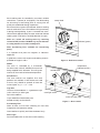
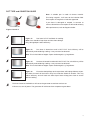
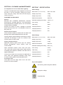
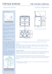
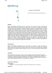
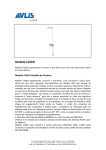
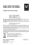
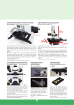
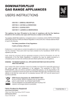
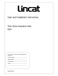
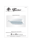
E3913i / E3914i Induction Ranges USER INSTRUCTIONS CAUTION - READ THESE INSTRUCTIONS BEFORE USING THIS APPLIANCE! Section 1 – GENERAL DESCRIPTION Section 2 – SAFETY and OPERATION Section 3 – COOKING HINTS Section 4 – INDUCTION ERROR CODES Section 5 – CLEANING and MAINTENANCE Section 6 – TROUBLESHOOTING Section 7 – SPECIFICATION This appliance has been CE-marked on the basis of compliance with the Low Voltage and EMC Directives for the voltages stated on the data plate. The appliance MUST BE installed by a competent person in compliance with the INSTALLATION AND SERVICING INSTRUCTIONS and National Regulations in force at the time. UK regulations are listed on the front of the Installation and Servicing Instructions. Regular servicing by a qualified person is recommended to ensure the continued safe and efficient performance of the appliance. WARNING - THE APPLIANCE MUST BE EARTHED. WARNING - PERSONS WITH PACEMAKERS SHOULD CONSULT THEIR G.P. BEFORE OPERATING THIS APPLIANCE. THIS UNIT OPERATES AT 18 - 22KHz AND THIS MAY AFFECT OLDER TYPES OF PACEMAKER. ENSURE ALL POT/PAN BASES ARE FLAT AND CLEAN PRIOR TO USE. THE AIR INTAKE FILTER MUST BE CLEANED REGULARLY TO REMOVE POTENTIAL OBSTRUCTIONS. THIS APPLIANCE CAN BE USED BY PERSONS WITH REDUCED PHYSICAL, SENSORY OR MENTAL CAPABILITIES OR LACK OF EXPERIENCE/KNOWLEDGE. PROVIDED SUCH INDIVIDUALS HAVE BEEN GIVEN INSTRUCTION CONCERNING USE OF THE APPLIANCE IN A SAFE WAY AND THAT THEY UNDERSTAND THE HAZARDS INVOLVED. CHILDREN SHALL NOT PLAY WITH THE APPLIANCE AND CLEANING/USER MAINTENANCE WILL NOT BE CARRIED OUT BY CHILDREN WITHOUT SUPERVISION. Upon receipt of the User's Instruction manual, the installer should instruct the responsible person(s) of the correct operation and maintenance of the unit. WEEE Directive Registration No. WEE/DC0059TT/PRO At end of unit life, dispose of appliance and any replacement parts in a safe manner, via a licenced waste handler. Units are designed to be dismantled easily and recycling of all material is encouraged whenever practicable. Falcon Foodservice Equipment HEAD OFFICE AND WORKS Wallace View, Hillfoots Road, Stirling. FK9 5PY. Scotland. SERVICELINE CONTACT Phone: 01438 363 000 Fax: 01438 369 900 T100767 Ref. 2 SECTION 1 - GENERAL DESCRIPTION SECTION 2 - SAFETY and OPERATION 4 x 5kW, individually controlled, marked cooking zones on a glass-ceramic cooktop. Mounted upon 6.4kW twin-fan convection oven with 5 shelf positions. WARNING - IF GLASS-CERAMIC TOP IS CRACKED OR BROKEN, IMMEDIATELY DISCONNECT APPLIANCE FROM POWER SUPPLY AND CONTACT YOUR SERVICE AGENT. WARNING - PERSONS WITH PACEMAKERS SHOULD CONSULT THEIR G.P. BEFORE OPERATING THIS APPLIANCE. THIS UNIT OPERATES AT 18 - 22KHz AND THIS MAY AFFECT OLDER TYPES OF PACEMAKER. The air intake filter MUST be in position during operation and MUST be cleaned regularly. DO NOT obstruct air filter entry below front of appliance or flue exit at top/ rear. This unit must be installed by a suitably qualified person. A mains input connecting cable is not supplied with unit. A suitable cable should be provided by the installer, conforming to at least 6mm², type H07RN-F. Figure 1 Use of proper pan type is essential for correct induction hob operation (Refer to Section 3). Do not place any metal objects, such as kitchen utensils, cutlery, aluminium foil or plastic vessels upon the glass-ceramic hob. Items such as rings, watches, bracelets, etc. worn by the user could become hot when in close proximity to cooking zone. Do not place credit cards, etc. on glass-ceramic top as data could be wiped. Never leave induction hob unsupervised when in use. The glass-ceramic top must NOT be used for storage. Do not place cloths etc. over appliance rear. This may impede flue outlet and cause overheating of appliance. SECTION 3 - OPERATION INDUCTION HOB Use of correct pan type is essential for proper operation. Suitable pans are those made with ferrous materials, ie, ferrous stainless steel, steel. Use a magnet to check, if magnet sticks to base, the pan should be OK to use. Warning – this only tests function – not quality! Poor quality will reduce efficiency and performance. Always place pans centrally upon cooking zone for optimum performance and safety. Optimum pan diameter is 270mm. Do not use pans of less than 120mm diameter. If a pan base is damaged or warped, ie concave or convex, discontinue use as this will seriously affect performance. 2 Each cooking zone is controlled by a marked, variable control from 1 (lowest) to 10 (highest). The ideal setting for simmering or fast boiling pans of varying size will quickly be established through experience. control knob Each control has a green LED indicator. When a cooking zone is switched on, the LED indicator will light and stay lit during heating/cooking. If pan is removed from zone, LED will flash approximately once per second to indicate cooking zone is still active, awaiting detection of a pan. After use, switch off cooking zones by returning control to OFF position. DO NOT rely on pan detector or safety features to isolate cooking zone. LED indicator (green) Note: Positioning lines available for centralising pot(s). It is important that pots are magnetic or inductionapproved. A guide to the correct use of pans and cooking zones is provided on Pages 4 and 5. Figure 2 - Hob zone control OVEN temperature indicator (amber) The oven is controlled by a thermostat. An amber neon, when lit, indicates that current is being supplied to the elements. This will go out when oven has reached selected temperature. control knob Grid Shelves Two oven shelves are supplied. Five shelf positions are available. If two shelves are used at once, they should be spaced at least two runners apart, e.g. 1 – 3, 3 – 5 etc. Tray Size The oven accommodates 1 x 1 gastronorm trays (530 x 325mm) or other types up to 530 x 500mm. oven light switch Trays and dishes should always be located centrally on the shelves. mains on neon (red) Figure 3 - Oven control Pre-Heating Time Allow at least 45 mins from switching on from cold, irrespective of temperature setting. Insert food items quickly and close the doors firmly. Oven Light Push and hold switch to view items while cooking. 3 Figure 4 Zone will not Operate Ø110mm pan - If inner circle markings can be seen, pan is too small. Detection will prevent cooking using this size of pan. Figure 5 Zone will Operate Ø120mm pan - Ideal, positioned centrally. Inner circle markings cannot be seen. Note: Positioning lines are available for central positioning of pan. Figure 6 Zone will not Operate Important Note: Ø120mm pan - Ideal but positioned incorrectly. Only half the pan contents will cook as outer circle markings have been compromised. Figure 7 Zone will Operate however: Ø180mm pan - Ideal for cooking. Although pot is positioned incorrectly, whole pan area will cook. Outer circle markings have not been compromised. (THIS IS NOT RECOMMENDED PRACTICE) Figure 8 Zone will Operate Ø270mm pan - Ideal for cooking, positioned centrally. Note: Positioning lines available to centralise pot. Figure 9 Zone will Operate - however: Ø270mm pan - Ideal for cooking but positioned incorrectly. Only three-quarters of pan will cook as outer circle markings have been compromised. 4 Using pans of less than Ø270mm will reduce the power output of the coils. POT TYPE and CONDITION GUIDE Note: A suitable pan is made of ferrous material. This being magnetic, it will react to the induction field. Ensure pots are magnetic or induction approved. If pan base is damaged or warped, ie concave or convex, discontinue use or replace as this could seriously affect performance, refer to diagrams below. Figures 10 and 11 Figure 12 Pan base is FLAT and ideal for cooking. Note: Pans should be kept clean and free from damage. Dirty, damaged pans effect efficiency. Figure 13 Pan base is bowed out and is NOT FLAT. Unit efficiency will be dramatically reduced during cooking. It may not even be detected. Note: This is also liable to happen if pans are damaged, e.g. large dents. Figure 14 Pot base is bowed inward and is NOT FLAT; The unit efficiency will be dramatically reduced during cooking. It may not even be detected. Note: This is also liable to happen if pans are damaged, e.g. large dents. Figure 15 Excessive food spillage stuck to pan base will impinge balance of pan. One side of utensil will be further away from induction field than another. This may reduce efficiency and will cook one side of pan faster. Keep pans clean to ensure efficient cooking. The three instances marked thus will cause the generator to overheat and cut out. If this occurs, turn off power. The generator will self-reset when temperature goes down. 5 SECTION 3 - COOKING HINTS SECTION 4 - INDUCTION ERROR CODES 1. Before use, ensure hob surface is clean, dry and free of grease. Remove any burnt on food debris. DO NOT remove or attempt to repair/replace ANY component or part of this unit other than the air filter. 2. Familiarise yourself with cooking area and control settings. If an error occurs, the control panel LEDs will flash to indicate an error code. 3. Each cooking zone has a power capacity of 5kW. One LONG flash will be followed by a series of shorter flashes. The number of “short” flashes corresponds to a value in the “code” column of the following table. 4. Each zone is governed by individual energy regulator. 5. Control setting is from 1 to 10. (1 - lowest setting, 10 - highest). 6. Boiling, steaming, poaching, stewing, pot roasting, deep and shallow frying can be achieved on the hob. ie. 5 short flashes corresponds to Error Code: 05 - Control Unit Failure 7. Ferritic cooking vessels must be used. SECTION 5 - TROUBLESHOOTING 8. To boil liquid, follow this procedure: Fill and position pan centrally within cooking zone. Turn appropriate switch dial to 10. When boiling occurs, reduce setting and continue to cook by simmering. If a fault occurs during use, an error code will be displayed in a series of flashes. These correspond to the numbers in code column of the table on Page 7. 9. The lower setting is dependent on amount and density of liquid and also starch content. For example, 6 short flashes followed by an extended flash indicates error code 06 (Generator internal temperature too high). 10. Skill is required to control simmering and the ability to select a corresponding temperature setting will improve with practice. The codes are provided to diagnose possible faults and the action required to remedy any such condition. 11. Any spillage should be cleaned from hob surface as soon as practically possible. Note: Most faults can be rectified by simply switching the unit off for 10 seconds. After this time, turn power back on at mains supply. Failure to clean filter regularly may cause problems that will not be covered by warranty. The air intake filter MUST ALWAYS be in place during operation. Wipe glass-ceramic hob clean using a damp cloth and warm, soapy water. For heavy stains, use a scraper while cooking zone is still warm. Wipe down with a damp cloth when zone is cool. Chef's Tips Always pre-heat oven to desired temperature. Use appropriate trays and NEVER overload oven. Place food centrally upon the shelves. Avoid opening oven doors during cooking process. If removing food from oven, ensure doors are fully open. Cooking times are dependant upon the following: Pre-heat temperature Food temperature (e.g. frozen, chilled or ambient) Shelf load / Oven load / Size and weight of food 6 If fault continues to occur after this action then please refer to the table. It will provide the solution to rectify the condition. SUPPLY PROTECTION DEVICE The appliance is fitted with a miniature circuit breaker (MCB) as additional protection against over current. If unit fails to operate or show any operational indicators, Follow details in Error Code Table before calling a service engineer. The symptoms may indicate a failed induction generator. ERROR CODE TABLE Code Error Cause Action by user Unsuitable pan material Use suitable pan Wrong or defective coil Call Service Engineer. No inductor current Inductor connection failure Call Service Engineer. 03 Heat sink temperature too high Air routes blocked. Fan filter clogged. Generator temperature sensor defective Clear air routes. Clean fan air intake filter. If still faulty, call Service Engineer. 04 Cooking zone temperature too high or too low 05 Control unit failure Control / switch assembly is faulty or wired incorrectly Call Service Engineer. 06 Internal temperature too high Air routes blocked. Fan filter clogged. Temperature sensor faulty, external heat sources too close Clear air routes. Clean fan filter. Remove any external heat source. If still faulty, call Service Engineer. 07 Cooking zone temperature sensor Short circuit at temperature sensor Call Service Engineer. 08 Mains phase failure Fault in mains supply Call Service Engineer. 10 Communication error Failure in LIN or CAN-Bus No connection between keyboard and generator Disconnect from mains. Reconnect and test again. Call Service Engineer. 11 Initialisation error Failure while initialising hardware Wait. Generator will reset every 30 seconds. Try switching off and on. Call Service Engineer. 12 Mains current failure Failure while generator measures mains current Call Service Engineer. 13 Mains connection error Mains voltage too high or too low Call Service Engineer. 14 Mains adaptor error Mains voltage too high or too low Call Service Engineer. 15 Protective electrical circuit Pan empty, 01 Hardware over coil 02 Pan empty Remove pan, check pan base. Switch Pan base distorted off, allow zone to cool and try again. Coil temperature sensor faulty If still faulty, call Service Engineer. faulty sensor Remove pan, switch off and allow cooking zone to cool. Call Service Engineer. 7 SECTION 6 - CLEANING and MAINTENANCE It is important to clean air intake filter regularly. The filter is located below body of appliance at front and RH side. It can be removed by sliding out of front. Clean using hot, soapy water and re-fit after drying. (Refer to Figure 5). SECTION 7 - SPECIFICATION E3913i Range Dimensions (w x d x h mm) 900 x 770 x 890 Weight (unpacked) 140kg Weight (unpacked) 159kg Electrical connection 400V 3N~ Individual cooking zone rating 3.5kW ( x 4) Oven rating 6kW Total rating 20kW Amps per phase L1 29A Amps per phase L2 29A Amps per phase L3 29A CLEANING THE APPLIANCE General BEFORE ANY CLEANING OPERATION, ISOLATE ELECTRICITY AT MAIN SWITCH. THE APPLIANCE MUST NEVER BE CLEANED WITH A JET OF WATER OR BE STEAM CLEANED. Surfaces are easier to clean if spillage is removed before it becomes burnt on. It is advisable to clean unit daily, after use. Stainless Steel Surfaces These surfaces should be cleaned with hot water and detergent then dried and polished with a soft cloth. Cleaning agents containing bleach, abrasives or caustic chemicals will damage or stain the stainless steel surfaces and must not be used. E3914i Range Dimensions (w x d x d mm) 900 x 770 x 890 Weight (unpacked) 140kg Weight (unpacked) 159kg Electrical connection 400V 3N~ Individual cooking zone rating 5kW ( x 4) Wipe enamelled surfaces clean while still warm. Use a soft cloth and hot soapy water. Badly stained, removable parts should be soaked in hot water with an approved detergent. Oven rating 6.4kW Total rating 26.4kW Amps per phase L1 29A If parts are not able to be removed, the application of warm water with approved detergent using nylon or scotch cleaning pads will provide good results. Amps per phase L2 43A Amps per phase L3 43A Vitreous Enamel Surfaces Approved cleaning agents which bear the Vitreous Enamel Development Centre (VEDC) mark are recommended. Ceran-glass Hob Clean glass with hot soapy water and a soft cloth. Do NOT use metal scrapers. Key to unit symbols Non-ionizing, electro-magnetic radiation. Dangerous voltage Equipotentiality 8 9