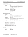
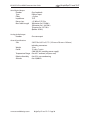
1
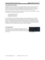
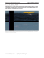
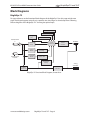
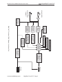
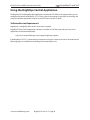
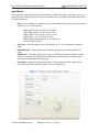
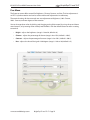
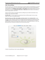
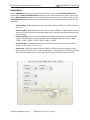
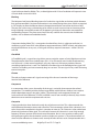
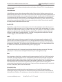
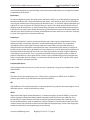
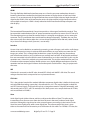
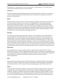
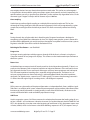
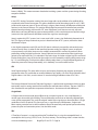
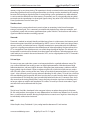
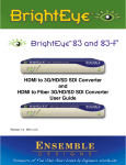
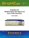
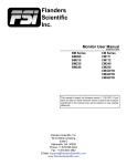
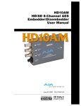
3G/HD/SD SDI to HDMI Converter User Guide
BrightEye 72 and 72-F
TM
72 and 72-F
3G/HD/SD SDI
to HDMI Converter
User Guide
Revision 1.4 SW v1.2.6
www.ensembledesigns.com
BrightEye 72 and 72-F - Page 1
3G/HD/SD SDI to HDMI Converter User Guide
BrightEye 72 and 72-F
TM
Contents
Product Overview and Functional Description
4
Use with Any HDMI Monitor
4
SDI Input
4
Optical Input with the 72-F
4
Test Signal Generator
4
Video Proc Amp and Color Corrector
4
Audio Metering Overlay and Disembedding
5
Graticule Overlay
5
Closed Caption Decoding
6
Timecode Reader
6
Horizontal and Vertical Shift
7
Block Diagrams
8
BrightEye 72
8
BrightEye 72-F
10
Applications12
Rear Connectors
13
Power Connection
13
USB Connector
13
HDMI Out
13
Audio Out
13
3G/HD/SD SDI Out
14
3G/HD/SD SDI In
14
Optical Input (BrightEye 72-F)
14
Module Configuration and Control
15
Front Panel Controls and Indicators
15
Status Indicators
15
Adjusting Parameters from the Front Panel
16
Front Panel Control and On-Screen Display
16
Examples of Using the Front Panel in Conjunction with On-Screen Display
17
www.ensembledesigns.com
BrightEye 72 and 72-F - Page 2
3G/HD/SD SDI to HDMI Converter User Guide
Using the BrightEye Control Application
BrightEye 72 and 72-F
TM
20
Software Version Requirement
20
Input Menu
21
Proc Menu
22
Color Correct Menu
23
Audio Menu
24
Config Menu
25
Captions Menu
26
Timecode Menu
27
Software Updating
28
Warranty28
Factory Service
28
Specifications29
Glossary31
www.ensembledesigns.com
BrightEye 72 and 72-F - Page 3
3G/HD/SD SDI to HDMI Converter User Guide
BrightEye 72 and 72-F
TM
Product Overview and Functional Description
The BrightEye 72/72-F turns any High Definition Multimedia Interface (HDMI) display into a monitoring
solution with professional monitoring features. With the BrightEye 72/72-F, you can monitor any type
of digital video signal, including 3 Gb/s signals.
Use with Any HDMI Monitor
The BrightEye 72/72-F can be used with any HDMI monitor. Because there is a wide range of HDMI
monitors available, you have a lot of choices when it comes to selecting which particular HDMI
monitor you want to use.
SDI Input
The BrightEye 72 has an SDI input and a reclocked loopback SDI output. The input can be 1.5 or
3 Gb/s HD SDI or SD SDI. The loopback SDI output is a copy of the SDI input. The key features, such as
on-screen display of audio and open captions, are accessed through the HDMI output.
Optical Input with the 72-F
The BrightEye 72-F offers an optical input instead of the SDI input of the BrightEye 72.
Test Signal Generator
The built-in test signal generator, useful for troubleshooting, inserts the signal at the front of the
signal path, so its behavior is functionally the same as cabling a test signal generator into a BNC input.
Use the test signal generator and adjust the BrightEye 72 as needed to set up your particular HDMI
monitor.
The test signal generator provides a number of test patterns including SMPTE bars with PLUGE, which
is useful for monitor alignment.
Video Proc Amp and Color Corrector
The Proc Amp and Color Corrector functions provide precise control over the output video levels. A
variety of controls are provided for making exact adjustments to produce correct luminance and color
rendition on the monitor and can be used with the built-in test signals. Adjustments are performed at
full 10-bit SDI resolution.
www.ensembledesigns.com
BrightEye 72 and 72-F - Page 4
BrightEye 72 and 72-F
3G/HD/SD SDI to HDMI Converter User Guide
TM
HDMI monitor output example illustrating audio metering overlay, graticule overlay, closed caption
decoding, and timecode reader.
Graticule
Open Captions
Timecode
Audio Meters
Audio Metering Overlay and Disembedding
The BrightEye 72/72-F has a sophisticated audio metering overlay capability
that uses four groups of four-channel on-screen VU meters. It includes a hanging
peak level indicator and a user-adjustable peak (headroom) indicator. You can
disembed and visually monitor up to sixteen channels of audio. Up to eight
channels of audio can be passed through the HDMI output.
Audio metering
overlay
Graticule Overlay
A built-in graticule generator puts up Safe Title and Safe Action reference markers as well as SD Safe
markers on HD signals. There are thin lines running from top to bottom that indicate the SD protect
area. These graticule reference markers aid in seeing how content is aligned, facilitating film transfer,
post production and quality control measurements relating to picture location for both the 4:3 and
16:9 aspect ratios. Safe Title displays the safe title boxes. SD Protect Only displays only the SD Protect
area without displaying the safe title boxes. You can adjust the color and intensity of the graticules or
turn graticules off.
www.ensembledesigns.com
BrightEye 72 and 72-F - Page 5
3G/HD/SD SDI to HDMI Converter User Guide
BrightEye 72 and 72-F
TM
Closed Caption Decoding
The BrightEye 72/72-F has a caption reader in the video path that decodes caption data. After being
decoded, a character generator system in the BrightEye 72/72-F overlays the captions onto the
video. The video is then sent through the HDMI output to be displayed on screen. This is useful for
compliance monitoring to be sure that all the captions are present in the broadcast signal.
The CEA-608 and CEA-708 standards for closed captions are specific to NTSC-based television systems.
Accordingly, they are supported for these input signals:
Standard Definition 525/59.94
High Definition 1080i/59.94
High Definition 720p/59.94
Under U.S. federal law, all consumer television receivers above a certain display size sold in the U.S.
must include decoding and display of closed caption data. However, that requirement is only for
over the air (or cable) broadcast signals received through the tuner input. The HDMI input of these
displays is not required to support closed captions. In fact, the HDMI standard provides no support
for captions in closed form. BrightEye 72/72-F is able to deliver open captions to an HDMI display by
rendering them as actual image content with its built-in character generator.
Timecode Reader
The video path includes a timecode reader. BrightEye 72/72-F can
read and display running timecode from either DVITC (Digital Vertical
Interval Time Code) on SD SDI inputs, or ATC (Ancillary Time Code) on
HD SDI inputs.
www.ensembledesigns.com
BrightEye 72 and 72-F - Page 6
Timecode display
3G/HD/SD SDI to HDMI Converter User Guide
BrightEye 72 and 72-F
TM
Horizontal and Vertical Shift
The BrightEye 72/72-F can shift images horizontally and/or vertically to enable inspection of content
in the horizontal and vertical intervals outside of the picture itself, such as embedded audio, closed
caption data blocks, and blanking edges of the signal.
HDMI monitor output example illustrating Horizontal shift. H and V shift enables inspection of content in
the horizontal and vertical intervals.
www.ensembledesigns.com
BrightEye 72 and 72-F - Page 7
BrightEye 72 and 72-F
3G/HD/SD SDI to HDMI Converter User Guide
TM
Block Diagrams
BrightEye 72
For your reference, see the functional block diagram of the BrightEye 72 on this page and the next
page. The diagram appears twice, first in a portrait view, then larger as a landscape view. Following
that are diagrams of the BrightEye 72-F showing the optical input.
Graticule Gen
Input Status Display
Test Signal
Gen
On Screen Controls
3G/HD/SD SDI
In
3G/HD/SD SDI
Loopback
Video Proc
& Color
Corrector
Overlay
Combiner
H&V
Delay
Caption
Reader
Open Caption
Decoding
Timecode
Reader
Timecode
Window Gen
Audio Meter
Overlay
Analog
Audio Out
Audio Out
Selection
16 Chan
Audio Demux
BrightEye 72 Functional Block Diagram, Portrait View
www.ensembledesigns.com
BrightEye 72 and 72-F - Page 8
HDMI Out
3G/HD/SD SDI
In
3G/HD/SD SDI
Loopback
16 Chan
Audio Demux
Test Signal
Gen
Graticule Gen
Overlay
Combiner
Input Status Display
Open Caption
Decoding
On Screen Controls
Caption
Reader
Timecode
Window Gen
H&V
Delay
Timecode
Reader
Audio Meter
Overlay
Audio Out
Selection
BrightEye 72 Functional Block Diagram, Landscape View
Video Proc
& Color
Corrector
HDMI Out
Analog
Audio Out
BrightEye 72 and 72-F - Page 9
www.ensembledesigns.com
BrightEye 72 and 72-F
TM
3G/HD/SD SDI to HDMI Converter User Guide
BrightEye 72 and 72-F
3G/HD/SD SDI to HDMI Converter User Guide
TM
BrightEye 72-F
For your reference, see the functional block diagram of the BrightEye 72-F on this page and the next
page showing the optical input. The diagram appears twice, first in a portrait view, then larger as a
landscape view.
Graticule Gen
Input Status Display
Test Signal
Gen
On Screen Controls
Optical In
3G/HD/SD SDI
Loopback
Video Proc
& Color
Corrector
Overlay
Combiner
H&V
Delay
Caption
Reader
Open Caption
Decoding
Timecode
Reader
Timecode
Window Gen
Audio Meter
Overlay
16 Chan
Audio Demux
Analog
Audio Out
Audio Out
Selection
BrightEye 72-F Functional Block Diagram, Portrait View
www.ensembledesigns.com
HDMI Out
BrightEye 72 and 72-F - Page 10
Optical In
3G/HD/SD SDI
Loopback
16 Chan
Audio Demux
Test Signal
Gen
Graticule Gen
Overlay
Combiner
Input Status Display
Open Caption
Decoding
On Screen Controls
Caption
Reader
Timecode
Window Gen
H&V
Delay
Timecode
Reader
Audio Meter
Overlay
Audio Out
Selection
BrightEye 72-F Functional Block Diagram, Landscape View
Video Proc
& Color
Corrector
HDMI Out
Analog
Audio Out
BrightEye 72 and 72-F - Page 11
www.ensembledesigns.com
BrightEye 72 and 72-F
TM
3G/HD/SD SDI to HDMI Converter User Guide
BrightEye 72 and 72-F
3G/HD/SD SDI to HDMI Converter User Guide
TM
Applications
Use BrightEye 72/72-F with any HDMI monitor in broadcast production and distribution, QC,
engineering, post production, and the control room. In addition to video, you can also monitor
ancillary data such as closed captions, timecode, and audio. Graticules are available to align titles. Use
the BrightEye 72/72-F in studio applications where you need to adjust the color temperature of on-set
monitors so they look right on camera.
The BrightEye 72/72-F converts 3G/HD/SD SDI video signals to HDMI to provide professional
monitoring capabilities using an HDMI display. In the example below, the program feed from a server
goes into the SDI Input BNC connector of the BrightEye 72 and loops back out through the 3G/HD/
SD SDI Output BNC connector to the router. The input SDI signal is converted to HDMI and sent out
through the HDMI Out connector to an HDMI monitor.
Video
Server
3G/HD/SD
SDI input
BrightEye 72
HDMI
output
HDMI
monitor
Reclocked
loopback
SDI output
Routing
Switcher
www.ensembledesigns.com
BrightEye 72 and 72-F - Page 12
3G/HD/SD SDI to HDMI Converter User Guide
BrightEye 72 and 72-F
TM
Rear Connectors
All connections to the BrightEye 72/72-F are made on the rear of the unit. Refer to the illustration
below as a reference for the rear connectors. A more detailed explanation of the rear connectors
follows immediately below.
Power Connection
Connect the modular power supply to the 12-volt DC power input connection on the far left of the
unit. Use the locking ring to secure it. If you don’t have a power supply, contact Ensemble Designs to
purchase one.
USB Connector
Connect the USB port to a PC or Mac running BrightEye software for more comprehensive control,
diagnostics, and upgrades to the unit. The BrightEye PC/Mac Control software is included on the CD
that came with your unit. You can also download the software from this URL:
http://www.ensembledesigns.com/support/brighteye-support/
HDMI Out
The High Definition Multimedia Interface (HDMI) is an uncompressed, all-digital interface that
transmits digital video and eight channels of digital audio. The mapping of the first 8 channels of
audio on the incoming SDI signal will pass through the HDMI output. HDMI is a bit-serial interface that
carries the video content in digital component form over multiple twisted-pairs. The HDMI interface
standard supports limited cable length as compared to SD and HD SDI. The use of cables over 10m (30
feet) is not recommended. Connect the HDMI output to your video monitor.
Audio Out
The Audio Out connector provides two channels of balanced analog audio. This connector is fitted
with a pluggable terminal block that accepts bare wire leads. Wires can be inserted into the small
round holes. Depress the orange tab to release them.
Follow the legend to connect the Ground (G), Positive (+), and Negative (-) connections for each signal.
Ch 1 corresponds to the left channel in a stereo system, and Ch 2 corresponds to the right channel.
If connecting to an unbalanced (single-ended) destination, such as a consumer speaker amplifier, with
shielded coaxial style audio cable, connect the center conductor to the Positive (+) terminal. Then
connect the outer conductor to both the Ground (G) and Negative (-) terminals. Analog reference
levels can be configured from the BrightEye Control application.
www.ensembledesigns.com
BrightEye 72 and 72-F - Page 13
3G/HD/SD SDI to HDMI Converter User Guide
BrightEye 72 and 72-F
TM
3G/HD/SD SDI Out
The SDI Out BNC provides reclocked loopback output of the input video signal. Connect this BNC to a
video destination such as a router, production switcher, or broadcast monitor.
3G/HD/SD SDI In
This BNC input accepts SD SDI, HD SDI, or 3 Gb/s HD SDI video signals with or without embedded
audio. The mapping of the first 8 channels of audio on the incoming SDI signal will pass through the
HDMI output.
Optical Input (BrightEye 72-F)
The BrightEye 72-F offers an optical input instead of the SDI input of the BrightEye 72. The optical
input accepts SD SDI, HD SDI, or 3 Gb/s HD SDI video signals with or without embedded audio. The
mapping of the first 8 channels of audio on the incoming optical signal will pass through the HDMI
output.
www.ensembledesigns.com
BrightEye 72 and 72-F - Page 14
3G/HD/SD SDI to HDMI Converter User Guide
BrightEye 72 and 72-F
TM
Module Configuration and Control
There are two methods for controlling and operating the BrightEye 72/72-F:
1. From the front panel (with or without on-screen display on the HDMI out);
2. With the BrightEye PC or Mac Control application.
When controlling the module from the front panel, most, but not all of the control settings and
parameter choices will be available. For more comprehensive control, use the BrightEye PC or Mac
Control application.
Front Panel Controls and Indicators
The front panel shown in the figure below provides status indicators and control over video and audio
output.
Status Indicators
The following status indicators are provided on the front panel:
•
In – Illuminates green when there is a valid input signal detected.
•
Adjust – Choices include Bright, Contrast, Chroma, and Hue. The LED will be green when the
parameter is set to its nominal setting. The LED will turn red when the parameter is adjusted
away from the nominal setting.
•
Display – Choices include CC (closed caption), Aud VU (Audio VU), TC (timecode), and
Graticule. The LED will be green if the parameter is turned on. The LED will extinguish if the
parameter is turned off.
•
Enable – Choices include Test (test signals) and H/V (horizontal and/or vertical shift). The LED
will be green if the parameter is turned on. The LED will extinguish if the parameter is turned
off.
•
Audio – Choices include Gain and VU.
The Gain LED will be green when the parameter is set to its nominal setting. The LED will turn
red when the parameter is adjusted away from the nominal setting.
The VU LED indicates the output audio level of the sum of channels 1 and 2. The LED will be
green when the audio level is at or below the digital reference level. The LED lights yellow
www.ensembledesigns.com
BrightEye 72 and 72-F - Page 15
3G/HD/SD SDI to HDMI Converter User Guide
BrightEye 72 and 72-F
TM
when the audio level is between the digital reference level and the peak threshold. The LED
lights red when the peak threshold is reached. Note that the digital reference level (sometimes
referred to as 0 VU) may be set by the user to -20 dBFS or -18 dBFS. Similarly, the user may set
the peak headroom to -2 dBFS or -10 dBFS. These two parameters are adjustable using the
BrightEye PC or Mac Control application.
•
Pwr (Power) – Illuminates green when the BrightEye unit has power and the internal voltage
regulator is functioning correctly.
Adjusting Parameters from the Front Panel
From the front panel, use the Mode, Left Arrow, and Right Arrow buttons to select and adjust
parameters.
Pressing the Mode button cycles through the parameters that can be modified from the front panel.
The LED of the currently selected parameter will blink. A quick press of the Mode button advances to
the next editable parameter. A longer press of the Mode button will back up to the previous editable
parameter.
Pressing the Right Arrow or Left Arrow advances or backs up through the choices for the currently
selected parameter, or increases (Right Arrow) or decreases (Left Arrow) the value of the selected
parameter.
Pressing the Right Arrow and Left Arrow simultaneously restores the selected parameter to its
default value.
Front Panel Control and On-Screen Display
By default, on-screen display is enabled. There are two controls in the BrightEye PC or Mac Control
application that enable aspects of the on-screen display.
1. The first control is the OSD Enable drop-down control in the Config menu in the BrightEye PC or
Mac Control application. The available selections for this control are the following:
•
Off – Turns off the on-screen display.
•
Input Status – Displays the input status only. Input status is shown near the upper left
corner of the monitor. Input status shows the input format, frequency, and embedded
audio presence in terms of group 1 (G1), group 2 (G2), group 3 (G3) and group 4 (G4).
•
Control Adjust – Displays the value of the currently selected front panel control at the
lower center portion of the monitor. For example, when the Chroma control is selected on
the front panel, the on-screen display (on the HDMI output) might read “Chroma 100 pcnt”
indicating it is set to 100%.
•
All – (Default selection) Displays both the input status and the current control value.
2. The second control relating to on-screen display is Include in OSD in the Color Correct menu in
the BrightEye PC or Mac Control application. If you want to be able to adjust the Red, Green and
Blue Offset and Gain controls from the front panel, you must turn on Include in OSD.
NOTE: There are no LEDs on the front panel to blink to indicate that any of these six Color
Correction controls are selected, but the on-screen display will show each of these controls as you
move through them by pressing the Mode button on the front panel.
www.ensembledesigns.com
BrightEye 72 and 72-F - Page 16
3G/HD/SD SDI to HDMI Converter User Guide
BrightEye 72 and 72-F
TM
Examples of Using the Front Panel in Conjunction with On-Screen Display
Example 1
The image below is showing the Chroma control. This example shows what you would see if you
pressed the Mode button on the front panel until the Chroma LED started blinking. The Chroma
control is indicated in the blue box. To the right of that is the specific parameter setting that you can
adjust. Pressing the Left Arrow decreases the value while pressing the Right Arrow increases the
value.
Notice also that the input status is displaying in the upper left area of the monitor image, indicating
input format, frequency, and the presence of embedded audio. This example also includes graticule
lines and audio meters.
Example of on-screen display while adjusting the Chroma control from the front panel
www.ensembledesigns.com
BrightEye 72 and 72-F - Page 17
3G/HD/SD SDI to HDMI Converter User Guide
BrightEye 72 and 72-F
TM
Example 2
The image below is showing the Caption Display control. This example shows what you would see if
you pressed the Mode button on the front panel until the CC LED started blinking.
Note: If the control Include in OSD in the Color Correct menu has been turned on,
you will need to press the Mode button an additional six times to move from the
Hue control to the Caption Display control. These additional six presses will step
through the six Color Correction adjustments in the on-screen display, although no
LEDs will blink on the front panel for these six controls.
Just like in the previous example, the editable parameter section is indicated in the blue box. To the
right of that is the specific value that you can adjust. Pressing the Left Arrow decreases the value
while pressing the Right Arrow increases the value.
Again, this example is displaying the input status in the upper left area of the monitor, indicating input
format, frequency, and the presence of embedded audio. This example also includes graticule lines
and audio meters.
Example of on-screen display while adjusting the Caption Display control from the front panel
www.ensembledesigns.com
BrightEye 72 and 72-F - Page 18
3G/HD/SD SDI to HDMI Converter User Guide
BrightEye 72 and 72-F
TM
Example 3
The image below is showing the Graticule control. This example shows what you would see if you
pressed the Mode button on the front panel until the Graticule LED started blinking. Graticule lines
are overlayed on top of the video. White graticule is shown below.
Note:
If the control Include in OSD in the Color Correct menu has been turned on,
you will need to press the Mode button an additional six times to move from the
Hue control to the Caption Display control. These additional six presses will step
through the six Color Correction adjustments in the on-screen display, although no
LEDs will blink on the front panel for these six controls.
Just like in the previous examples, the editable parameter section is indicated in the blue box. To the
right of that is the specific value that you can adjust. Pressing the Left Arrow decreases the value
while pressing the Right Arrow increases the value.
Again, this example is displaying the input status in the upper left area of the monitor, indicating input
format, frequency, and the presence of embedded audio. This example also includes audio meters.
Graticule
Example of on-screen display while adjusting the Graticule control from the front panel
www.ensembledesigns.com
BrightEye 72 and 72-F - Page 19
3G/HD/SD SDI to HDMI Converter User Guide
BrightEye 72 and 72-F
TM
Using the BrightEye Control Application
The BrightEye PC and BrightEye Mac applications included on CD-ROM are designed to allow you to
configure and control the BrightEye 72/72-F from a personal computer. Instructions for installing and
using this software application are given in the PDF manual on the CD-ROM.
Software Version Requirement
BrightEye PC or BrightEye Mac version 2.0 or later is required.
BrightEye PC/Mac Control application software is included on CD that came with your unit, or the
application can be downloaded here:
http://www.ensembledesigns.com/support/brighteye-support/
If the BrightEye 72/72-F is connected to a computer running this software, the menus described in the
following pages are available for controlling and monitoring the unit.
www.ensembledesigns.com
BrightEye 72 and 72-F - Page 20
3G/HD/SD SDI to HDMI Converter User Guide
BrightEye 72 and 72-F
TM
Input Menu
The Input menu indicates whether an input is detected and whether there is sync lock. It also shows
which groups of audio channels are being used, whether there is an HDMI monitor detected and the
Test Pattern selected.
•
Input – shows whether or not there is an input signal detected. Types of input signals that the
BrightEye 72/72-F will accept are:
1080i (SMPTE 274M -4,5,6) 50, 59.94 or 60 Hz
720p (SMPTE 296M -1,2,3) 50, 59.94 or 60 Hz
1080p (SMPTE 274M -9,10,11) 23.98, 24, 25 Hz
1080sF (RP211 -14,15,16) 23.98, 24, 25 Hz
1080p (SMPTE 424M, 425M), 50, 59.94, 60, Level A
525i, 625i (SMPTE 259M)
•
Sync Lock – indicates whether or not the BrightEye 72/72-F is sync locked to a reference
signal.
•
Embedded Aud – shows which groups of audio channels, if any, are embedded in the
input.
•
HDMI Status – indicates whether or not there is an HDMI monitor present. When an HDMI
monitor is connected, this field will show “HDMI Native.” When there is no HDMI monitor
connected, this field will show “No Display.”
•
Test Pattern – reflects the selected Test Pattern. Choices include: Off, Bars, Black, Flat 20,
Flat 80, Window 20/80, 10 Step, Bars Blue Only, and Dig Blanking.
www.ensembledesigns.com
BrightEye 72 and 72-F - Page 21
3G/HD/SD SDI to HDMI Converter User Guide
BrightEye 72 and 72-F
TM
Proc Menu
The Processor menu offers controls for Brightness, Chroma, Contrast, and Hue. The Hue adjustment is
an NTSC-style Hue rotation and can be used to make small adjustments in colorimetry.
The nominal settings for these controls are: zero adjustment to Brightness, 100% Chroma,
100% Contrast, and zero degrees of Hue rotation.
You can change these values by clicking and dragging on the slider control, by using the up and down
arrow buttons, or by entering values directly into the fields. Click the default button to return a setting
to nominal.
•
Bright – adjusts the brightness (range is -30 to 30, default is 0).
•
Chroma – adjusts the percentage of chroma (range is 0 to 150%, default is 100%).
•
Contrast – adjusts the percentage of contrast (range is 0 to 150%, default is 100%).
•
Hue – adjusts the hue of the signal ±180 degrees (range is -180 to 180, default is 0°).
www.ensembledesigns.com
BrightEye 72 and 72-F - Page 22
3G/HD/SD SDI to HDMI Converter User Guide
BrightEye 72 and 72-F
TM
Color Correct Menu
The Color Correct menu provides fine adjust for the red, green and blue in the HDMI output so that the
monitor matches other sources. The gain and offset controls enable you to correct for white balance
and black balance. The Red Offset, Green Offset and Blue Offset controls affect the blacks and can be
adjusted from -50 to 50. The Red Gain, Green Gain and Blue Gain controls affect the white balance
and can be adjusted from 50 to 185%.
Adjust the values of the gain and offset controls by clicking the up and down arrow buttons or by
entering values directly into the fields.
Include in OSD – Turn this control on to include these Gain and Offset controls in the on-screen
display. This control is turned off by default.
Note about front panel LEDs and the Offset and Gain controls: When Include in OSD is turned
on, these six Color Correction controls will be included among those that can be selected by pressing
the Mode button on the front panel. These six additional controls will fall between the Hue and CC
(closed caption) controls and will display their values on the on-screen display; however, no LEDs will
blink when they are selected, since they have no LED on the front panel.
Contact us if you’d like our Color Correction White Paper.
www.ensembledesigns.com
BrightEye 72 and 72-F - Page 23
3G/HD/SD SDI to HDMI Converter User Guide
BrightEye 72 and 72-F
TM
Audio Menu
Use the Audio Menu to select audio levels and audio channels. Use the Audio Digital Reference
control and the Audio Analog Reference control to set the audio reference level used in your facility.
Use the Peak Headroom control to adjust when the peak indicator turns from yellow to red. Use the
Analog Audio Out control to choose a pair of audio channels for output through the rear Audio Out
connector.
•
Audio Dig Ref – Audio Digital Reference Level. Choose either -20 dBFS or -18 dBFS, relative to
full scale.
•
Audio Anlg Ref – Analog Reference Level. Choose either -10 dBu or +4 dBu. Use this control to
select the nominal reference level for the analog inputs. Select the appropriate reference level
for your facility.
•
Peak Headroom – Use this control to determine how close to the maximum level the audio
signal can reach before turning from yellow to red. Available choices are: -2 dBFS, -3 dBFS,
-4 dBFS, -5 dBFS, -6 dBFS, -7 dBFS, -8 dBFS, -9 dBFS, -10 dBFS.
•
Anlg Audio Out – Select the channels you want to use for analog audio output. Available
choices are: Channels 1/2, 3/4, 5/6, 7/8.
•
Audio Level – Adjust the Audio Level from -30dB to 12dB by clicking and dragging on the
slider control, by using the up and down arrow buttons, or by entering a value directly into the
field. Click the default button to return the Audio Level to the default setting of zero dB.
www.ensembledesigns.com
BrightEye 72 and 72-F - Page 24
3G/HD/SD SDI to HDMI Converter User Guide
BrightEye 72 and 72-F
TM
Config Menu
•
Audio Meters – The BrightEye 72/72-F’s audio metering overlay capability uses four groups
of four-channel on-screen VU meters. It includes a hanging peak level indicator and a useradjustable peak (headroom) indicator. You can disembed and visually monitor up to sixteen
channels of audio. Available choices are: Off, Group 1, Groups 1/2, All Groups.
•
Colorspace Out – Choose either RGB 0 - 255 or RGB 16 - 235.
•
Graticule – The graticule generator puts up Safe Title and Safe Action reference markers as
well as SD Safe markers on HD signals. The graticule reference markers aid in seeing how
content is aligned, facilitating film transfer, post production, and quality control measurements
relating to picture location for both 4:3 and 16:9 aspect ratios. Safe Title displays the safe
title boxes. SD Protect Only displays only the SD Protect area without displaying the safe
title boxes. You can adjust the color and transparency of the graticules or turn graticules off.
Available choices are: Off, Safe Title, SD Protect Only.
•
Transparency – Adjusts the transparency of the graticule from 0 to 100%.
•
Color – Available graticule color choices are: White, Gray, Black, Red, Blue, Green.
•
HV Shift – The BrightEye 72/72-F can shift images horizontally and/or vertically to enable
inspection of content in the horizontal and vertical intervals outside of the picture itself, such
as embedded audio, closed caption data blocks, and blanking edges of the signal. Available
choices are: Off, Shift H, Shift V, Shift H V.
•
Mirror Mode –Use this control to turn Mirror Mode on or off. Mirror Mode flips the picture left
to right as if looking in a mirror. This mode is commonly used for reference monitors for on-air
talent, such as weather presenters, so they can view themselves in a mirrored image. Open
captions are displayed correctly when Mirror Mode is selected.
www.ensembledesigns.com
BrightEye 72 and 72-F - Page 25
3G/HD/SD SDI to HDMI Converter User Guide
•
BrightEye 72 and 72-F
TM
OSD Enable – Use this control to enable the on-screen display of the BrightEye 72/72-F
software controls. When enabled, the software controls display on the HDMI monitor. Available
choices are: Off, Input Status, Control Adjust, All. Input Status displays in the upper left corner
of the HDMI monitor. It shows the input format, frequency, and indicates if embedded audio
is present. Control Adjust displays in the lower center area of the HDMI monitor. It displays the
value of the control currently selected by the Mode button on the front panel.
Captions Menu
A caption decoder in the video path will read closed captions for an SD or HD signal. The captions
will be overlayed onto the video (open captions) and sent through the HDMI output to display on the
screen. This is useful for compliance to be sure that all the captions are present in the broadcast signal.
Caption Display – Available choices are: Off, CC1, CC2.
Caption Demo – This control is a demonstration mode of the caption capabilities of the BrightEye
72/72-F. In normal operation this control should be turned off.
www.ensembledesigns.com
BrightEye 72 and 72-F - Page 26
3G/HD/SD SDI to HDMI Converter User Guide
BrightEye 72 and 72-F
TM
Timecode Menu
The video path includes a timecode reader. BrightEye 72/72-F can read and display running timecode
from either DVITC (Digital Vertical Interval Time Code) on SD SDI inputs, or ATC (Ancillary Time Code)
on HD SDI inputs.
TC Display – Available choices are: On, Off.
VITC Select – Use this control to select the line on which VITC is present. Available choices are
Line 13, Line 14, Line 15, Line 16, Line 17, Line 18, Line 19, Line 20, Line 21.
www.ensembledesigns.com
BrightEye 72 and 72-F - Page 27
3G/HD/SD SDI to HDMI Converter User Guide
BrightEye 72 and 72-F
TM
Software Updating
Software upgrades for BrightEyes are available at:
http://www.ensembledesigns.com/support/brighteye-support/
Use BrightEye Mac or PC software to install the software update into your BrightEye.
Warranty
This unit is covered by a five-year limited warranty. If you require service (under warranty or not),
please contact Ensemble Designs and ask for customer service before you return the unit. This will
allow the service technician an opportunity to provide any other suggestions for identifying the
problem and to recommend possible solutions.
Factory Service
If you return equipment for repair, please get a Return Material Authorization Number (RMA) from the
factory first.
Ship the product and a written description of the problem to:
Ensemble Designs, Inc.
Attention: Customer Service RMA #####
870 Gold Flat Rd.
Nevada City, CA. 95959 USA
(530) 478-1830
Fax: (530) 478-1832
[email protected]
http://www.ensembledesigns.com
Be sure to put your RMA number on the outside of the box.
www.ensembledesigns.com
BrightEye 72 and 72-F - Page 28
3G/HD/SD SDI to HDMI Converter User Guide
BrightEye 72 and 72-F
TM
Specifications
Serial Digital Input for BrightEye 72
Number One
Type 1.485 Gb/s HD Serial Digital (SMPTE 274M, 292M or 296M)
2.97 Gb/s HD Serial Digital (SMPTE 424M, 425M), Level A
SD Serial Digital (270 Mb/s SMPTE 259M)
Impedance 75 Ω
Return Loss >15 dB to 2.97 GHz
Max Cable Length 300 meters for 270 Mb/s
100 meters for 1.485 Gb/s
70 meters for 2.97 Gb/s
(Belden 1694A)
Automatic Input Cable Equalization
Optical Input for BrightEye 72-F
Number One
ConnectorLC/UPC
Type 270 Mb/s (SMPTE 297M, optical equivalent of 259M)
1.485 Gb/s HD Serial Digital (SMPTE 274M, 272M or 296M)
2.97 Gb/s HD Serial Digital (SMPTE 424M, 425M)
Wavelength
830 to 1610 nm
Receiver Sensitivity -18 dBm
Max Cable Length 20 km (For greater distances, or higher power and larger loss
budgets, please contact the factory)
Fiber TypeSingle Mode
Multi-mode compatible with 8dB attenuation at transmit end
SDI Standards Supported
1080i (SMPTE 274M -4,5,6) 50, 59.94 or 60 Hz
720p (SMPTE 296M -1,2,3) 50, 59.94 or 60 Hz
1080p (SMPTE 274M -9,10,11) 23.98, 24, 25 Hz
1080sF (RP211 -14,15,16) 23.98, 24, 25 Hz
1080p (SMPTE 424M, 425M), 50, 59.94, 60, Level A
525i, 625i (SMPTE 259M)
HDMI Output
NumberOne
TypeHDMI 1.3
FormatFollows input
www.ensembledesigns.com
BrightEye 72 and 72-F - Page 29
3G/HD/SD SDI to HDMI Converter User Guide
BrightEye 72 and 72-F
TM
Serial Digital Output
Number One, loopback
Type Follows input
Delay< 5 μSec
Impedance 75 Ω
Return Loss >15 dB to 2.97 GHz
Max Cable Length 300 meters for 270 Mb/s
100 meters for 1.485 Gb/s
70 meters for 2.97 Gb/s
(Belden 1694A)
Analog Audio Output
Number
One stereo pair
General Specifications
Size
5.625” W x 0.8” H x 5.5” D (143 mm x 20 mm x 140 mm)
including connectors
Weight14 oz
Power
12 volts, 7 watts
(100-230 VAC modular power supply)
Temperature Range 0 to 40° C ambient (all specs met)
Relative Humidity 0 to 95%, non-condensing
Altitude
0 to 10,000 ft.
www.ensembledesigns.com
BrightEye 72 and 72-F - Page 30
3G/HD/SD SDI to HDMI Converter User Guide
BrightEye 72 and 72-F
TM
Glossary
AES/EBU
The digital audio standard defined as a joint effort of the Audio Engineering Society and the European
Broadcast Union. AES/EBU or AES3 describes a serial bitstream that carries two audio channels,
thus an AES stream is a stereo pair. The AES/EBU standard covers a wide range of sample rates and
quantizations (bit depths). In television systems, these will generally be 48 kHz and either 20 or 24 bits.
AFD
Active Format Description is a method to carry information regarding the aspect ratio of the video
content. The specification of AFD was standardized by SMPTE in 2007 and is now beginning to appear
in the marketplace. AFD can be included in both SD and HD SDI transport systems. There is no legacy
analog implementation. (See WSS).
ASI
A commonly used transport method for MPEG video streams, ASI or Asynchronous Serial Interface,
operates at the same 270 Mb/s data rate as SD SDI. This makes it easy to carry an ASI stream through
existing digital television infrastructure. Known more formally as DVB-ASI, this transport mechanism
can be used to carry multiple program channels.
Aspect Ratio
The ratio of the vertical and horizontal measurements of an image. 4:3 is the aspect ratio for standard
definition video formats and television and 16:9 for high definition. Converting formats of unequal
ratios is done by letterboxing (horizontal bars) or pillar boxing (vertical pillars) in order to keep the
original format’s aspect ratio.
Bandwidth
Strictly speaking, this refers to the range of frequencies (i.e. the width of the band of frequency) used
by a signal, or carried by a transmission channel. Generally, wider bandwidth will carry and reproduce
a signal with greater fidelity and accuracy.
Beta
Sony Beta SP video tape machines use an analog component format that is similar to SMPTE, but
differs in the amplitude of the color difference signals. It may also carry setup on the luminance
channel.
Bit
A binary digit, or bit, is the smallest amount of information that can be stored or transmitted digitally
by electrical, optical, magnetic, or other means. A single bit can take on one of two states: On/Off,
Low/High, Asserted/ Deasserted, etc. It is represented numerically by the numerals 1 (one) and 0
(zero). A byte, containing 8 bits, can represent 256 different states. The binary number 11010111, for
example, has the value of 215 in our base 10 numbering system. When a value is carried digitally, each
additional bit of resolution will double the number of different states that can be represented. Systems
that operate with a greater number of bits of resolution, or quantization, will be able to capture a
www.ensembledesigns.com
BrightEye 72 and 72-F - Page 31
3G/HD/SD SDI to HDMI Converter User Guide
BrightEye 72 and 72-F
TM
signal with more detail or fidelity. Thus, a video digitizer with 12 bits of resolution will capture 4 times
as much detail as one with 10 bits.
Blanking
The Horizontal and Vertical blanking intervals of a television signal refer to the time periods between
lines and between fields. No picture information is transmitted during these times, which are required
in CRT displays to allow the electron beam to be repositioned for the start of the next line or field.
They are also used to carry synchronizing pulses which are used in transmission and recovery of the
image. Although some of these needs are disappearing, the intervals themselves are retained for
compatibility purposes. They have turned out to be very useful for the transmission of additional
content, such as teletext and embedded audio.
CAV
Component Analog Video. This is a convenient shorthand form, but it is subject to confusion. It is
sometimes used to mean ONLY color difference component formats (SMPTE or Beta), and other times
to include RGB format. In any case, a CAV signal will always require 3 connectors – either Y/R-Y/B-Y,
or R/G/B.
Checkfield
A Checkfield signal is a special test signal that stresses particular aspects of serial digital transmission.
The performance of the Phase Locked-Loops (PLLs) in an SDI receiver must be able to tolerate long
runs of 0s and 1s. Under normal conditions, only very short runs of these are produced due to a
scrambling algorithm that is used. The Checkfield, also referred to as the Pathological test signal, will
“undo” the scrambling and cause extremely long runs to occur. This test signal is very useful for testing
transmission paths.
Chroma
The color or chroma content of a signal, consisting of the hue and saturation of the image.
See also Color Difference.
Component
In a component video system, the totality of the image is carried by three separate but related
components. This method provides the best image fidelity with the fewest artifacts, but it requires
three independent transmission paths (cables). The commonly used component formats are
Luminance and Color Difference (Y/Pr/Pb), and RGB. It was far too unwieldy in the early days of color
television to even consider component transmission.
Composite
Composite television dates back to the early days of color transmission. This scheme encodes the
color difference information onto a color subcarrier. The instantaneous phase of the subcarrier is the
color’s hue, and the amplitude is the color’s saturation or intensity. This subcarrier is then added onto
the existing luminance video signal. This trick works because the subcarrier is set at a high enough
frequency to leave spectrum for the luminance information. But it is not a seamless matter to pull
the signal apart again at the destination in order to display it or process it. The resultant artifacts of
dot crawl (also referred to as chroma crawl) are only the most obvious result. Composite television is
www.ensembledesigns.com
BrightEye 72 and 72-F - Page 32
3G/HD/SD SDI to HDMI Converter User Guide
BrightEye 72 and 72-F
TM
the most commonly used format throughout the world, either as PAL or NTSC. It is also referred to as
Encoded video.
Color Difference
Color Difference systems take advantage of the details of human vision. We have more acuity in our
black and white vision than we do in color. This means that we need only the luminance information to
be carried at full bandwidth, we can scrimp on the color channels. In order to do this, RGB information
is converted to carry all of the luminance (Y is the black and white of the scene) in a single channel.
The other two channels are used to carry the “color difference”. Noted as B-Y and R-Y, these two signals
describe how a particular pixel “differs” from being purely black and white. These channels typically
have only half the bandwidth of the luminance.
Decibel (dB)
The decibel is a unit of measure used to express the ratio in the amplitude or power of two signals. A
difference of 20 dB corresponds to a 10:1 ratio between two signals, 6 dB is approximately a 2:1 ration.
Decibels add while the ratios multiply, so 26 dB is a 20:1 ratio, and 14 dB is a 5:1 ratio. There are several
special cases of the dB scale, where the reference is implied. Thus, dBm refers to power relative to 1
milliwatt, and dBu refers to voltage relative to .775V RMS. The original unit of measure was the Bel
(10 times bigger), named after Alexander Graham Bell.
dBFS
In Digital Audio systems, the largest numerical value that can be represented is referred to as Full
Scale. No values or audio levels greater than FS can be reproduced because they would be clipped.
The nominal operating point (roughly corresponding to 0 VU) must be set below FS in order to have
headroom for audio peaks. This operating point is described relative to FS, so a digital reference level
of -20 dBFS has 20 dB of headroom before hitting the FS clipping point.
DVI
Digital Visual Interface. DVI-I (integrated) provides both digital and analog connectivity. The larger
group of pins on the connector are digital while the four pins on the right are analog.
EDH
Error Detection and Handling is a method to verify proper reception of an SDI or HD SDI signal at the
destination. The originating device inserts a data packet in the vertical interval of the SDI signal and
every line of the HD signal which contains a checksum of the entire video frame. This checksum is
formed by adding up the numerical values of all of the samples in the frame, using a complex formula.
At the destination this same formula is applied to the incoming video and the resulting value is
compared to the one included in the transmission. If they match, then the content has all arrived with
no errors. If they don’t, then an error has occurred.
Embedded Audio
Digital Audio can be carried along in the same bitstream as an SDI or HD SDI signal by taking
advantage of the gaps in the transmission which correspond to the horizontal and vertical intervals
of the television waveform. This technique can be very cost effective in transmission and routing, but
www.ensembledesigns.com
BrightEye 72 and 72-F - Page 33
3G/HD/SD SDI to HDMI Converter User Guide
BrightEye 72 and 72-F
TM
can also add complexity to signal handling issues because the audio content can no longer be treated
independently of the video.
Eye Pattern
To analyze a digital bitstream, the signal can be displayed visually on an oscilloscope by triggering the
horizontal timebase with a clock extracted from the stream. Since the bit positions in the stream form
a very regular cadence, the resulting display will look like an eye – an oval with slightly pointed left and
right ends. It is easy to see from this display if the eye is “open”, with a large central area that is free of
negative or positive transitions, or “closed” where those transitions are encroaching toward the center.
In the first case, the open eye indicates that recovery of data from the stream can be made reliably and
with few errors. But in the closed case data will be difficult to extract and bit errors will occur. Generally
it is jitter in the signal that is the enemy of the eye.
Frame Sync
A Frame Synchronizer is used to synchronize the timing of a video signal to coincide with a timing
reference (usually a color black signal that is distributed throughout a facility). The synchronizer
accomplishes this by writing the incoming video into a frame buffer memory under the timing
direction of the sync information contained in that video. Simultaneously the memory is being read
back by a timing system that is genlocked to a house reference. As a result, the timing or alignment of
the video frame can be adjusted so that the scan of the upper left corner of the image is happening
simultaneously on all sources. This is a requirement for both analog and digital systems in order to
perform video effects or switch glitch-free in a router. Frame synchronization can only be performed
within a single television line standard. A synchronizer will not convert an NTSC signal to a PAL signal,
it takes a standards converter to do that.
Frequency Response
A measurement of the accuracy of a system to carry or reproduce a range of signal frequencies. Similar
to Bandwidth.
H.264
The latest salvo in the compression wars is H.264 which is also known as MPEG-4 Part 10. MPEG-4
promises good results at just half the bit rate required by MPEG-2.
HD
High Definition. This two letter acronym has certainly become very popular. Here we thought it was all
about the pictures – and the radio industry stole it.
HDCP
(High-bandwidth Digital Content Protection) is a content encryption system for HDMI. It is meant to
prevent copyright content from being copied. Protected content, like a movie on a Blu-Ray disc is
encrypted by its creator. Devices that want to display the protected content, like a television, must
have an authorized key in order to decode the signal and display it. The entity that controls the HDCP
standard strictly limits the kinds of devices that are allowed decryption keys. Devices that decrypt the
content and provide an unencrypted copy are not allowed.
www.ensembledesigns.com
BrightEye 72 and 72-F - Page 34
3G/HD/SD SDI to HDMI Converter User Guide
BrightEye 72 and 72-F
TM
HDMI
The High Definition Multimedia Interface comes to us from the consumer marketplace where it is
becoming the de facto standard for the digital interconnect of display devices to audio and video
sources. It is an uncompressed, all-digital interface that transmits digital video and eight channels of
digital audio. HDMI is a bit serial interface that carries the video content in digital component form
over multiple twisted-pairs. HDMI is closely related to the DVI interface for desktop computers and
their displays.
IEC
The International Electrotechnical Commission provides a wide range of worldwide standards. They
have provided standardization of the AC power connection to products by means of an IEC line cord.
The connection point uses three flat contact blades in a triangular arrangement, set in a rectangular
connector. The IEC specification does not dictate line voltage or frequency. Therefore, the user must
take care to verify that a device either has a universal input (capable of 90 to 230 volts, either 50 or 60
Hz), or that a line voltage switch, if present, is set correctly.
Interlace
Human vision can be fooled to see motion by presenting a series of images, each with a small change
relative to the previous image. In order to eliminate the flicker, our eyes need to see more than 30
images per second. This is accomplished in television systems by dividing the lines that make up
each video frame (which run at 25 or 30 frames per second) into two fields. All of the odd-numbered
lines are transmitted in the first field, the even-numbered lines are in the second field. In this way, the
repetition rate is 50 or 60 Hz, without using more bandwidth. This trick has worked well for years, but
it introduces other temporal artifacts. Motion pictures use a slightly different technique to raise the
repetition rate from the original 24 frames that make up each second of film—they just project each
one twice.
IRE
Video level is measured on the IRE scale, where 0 IRE is black, and 100 IRE is full white. The actual
voltages that these levels correspond to can vary between formats.
ITU-R 601
This is the principal standard for standard definition component digital video. It defines the luminance
and color difference coding system that is also referred to as 4:2:2. The standard applies to both PAL
and NTSC derived signals. They both will result in an image that contains 720 pixels horizontally, with
486 vertical pixels in NTSC, and 576 vertically in PAL. Both systems use a sample clock rate of 27 MHz,
and are serialized at 270 Mb/s.
Jitter
Serial digital signals (either video or audio) are subject to the effects of jitter. This refers to the
instantaneous error that can occur from one bit to the next in the exact position of each digital
transition. Although the signal may be at the correct frequency on average, in the interim it varies.
Some bits come slightly early, others come slightly late. The measurement of this jitter is given
either as the amount of time uncertainty or as the fraction of a bit width. For 270 Mb/s SD video, the
www.ensembledesigns.com
BrightEye 72 and 72-F - Page 35
3G/HD/SD SDI to HDMI Converter User Guide
BrightEye 72 and 72-F
TM
allowable jitter is 740 picoseconds, or 0.2 UI (Unit Interval – one bit width). For 1.485 Gb/s HD, the
same 0.2UI spec corresponds to just 135 pico seconds.
Luminance
The “black & white” content of the image. Human vision had more acuity in luminance, so television
systems generally devote more bandwidth to the luminance content. In component systems, the
luminance is referred to as Y.
MPEG
The Moving Picture Experts Group is an industry group that develops standards for the compression
of moving pictures for television. Their work is an on-going effort. The understanding of image
processing and information theory is constantly expanding. And the raw bandwidth of both the
hardware and software used for this work is ever increasing. Accordingly, the compression methods
available today are far superior to the algorithms that originally made the real-time compression and
decompression of television possible. Today, there are many variations of these techniques, and the
term MPEG has to some extent become a broad generic label.
Metadata
This word comes from the Greek. Meta means “beyond” or “after.” When used as a prefix to “data,” it
can be thought of as “data about the data.” In other words, the metadata in a data stream tells you
about that data – but it is not the data itself. In the television industry, this word is sometimes used
correctly when, for example, we label as metadata the timecode which accompanies a video signal.
That timecode tells you something about the video, i.e., when it was shot, but the timecode in and of
itself is of no interest. But in our industry’s usual slovenly way in matters linguistic, the term metadata
has also come to be used to describe data that is associated with the primary video in a datastream. So
embedded audio will (incorrectly) be called metadata when it tells us nothing at all about the pictures.
Multi-mode
Multi-mode fibers have a larger diameter core than single mode fibers (either 50 or 62.5 microns
compared to 9 microns), and a correspondingly larger aperture. It is much easier to couple light energy
into a multi-mode fiber, but internal reflections will cause multiple “modes” of the signal to propagate
down the fiber. This will degrade the ability of the fiber to be used over long distances.
See also Single Mode.
NTSC
The color television encoding system used in North America was originally defined by the National
Television Standards Committee. This American standard has also been adopted by Canada, Mexico,
Japan, Korea, and Taiwan. (This standard is referred to disparagingly as Never Twice Same Color.)
Optical
An optical interface between two devices carries data by modulating a light source. This light source
is typically a laser or laser diode (similar to an LED) which is turned on and off at the bitrate of the
datastream. The light is carried from one device to another through a glass fiber. The fiber’s core acts
as a waveguide or lightpipe to carry the light energy from one end to another. Optical transmission
has two very significant advantages over metallic copper cables. Firstly, it does not require that the
www.ensembledesigns.com
BrightEye 72 and 72-F - Page 36
3G/HD/SD SDI to HDMI Converter User Guide
BrightEye 72 and 72-F
TM
two endpoint devices have any electrical connection to each other. This can be very advantageous
in large facilities where problems with ground loops appear. And secondly, and most importantly, an
optical interface can carry a signal for many kilometers or miles without any degradation or loss in the
recovered signal. Copper is barely useful at distances of just 1000 feet.
Oversampling
A technique to perform digital sampling at a multiple of the required sample rate. This has the
advantage of raising the Nyquist Rate (the maximum frequency which can be reproduced by a given
sample rate) much higher than the desired passband. This allows more easily realized anti-aliasing
filters.
PAL
During the early days of color television in North America, European broadcasters developed a
competing system called Phase Alternation by Line. This slightly more complex system is better able
to withstand the differential gain and phase errors that appear in amplifiers and transmission systems.
Engineers at the BBC claim that it stands for Perfection At Last.
Pathological Test Pattern – see Checkfield
Progressive
An image scanning technique which progresses through all of the lines in a frame in a single pass.
Computer monitors all use progressive displays. This contrasts to the interlace technique common to
television systems.
Return Loss
An idealized input or output circuit will exactly match its desired impedance (generally 75 ohms) as a
purely resistive element, with no reactive (capacitive or inductive) elements. In the real world, we can
only approach the ideal. So, our real inputs and outputs will have some capacitance and inductance.
This will create impedance matching errors, especially at higher frequencies. The Return Loss of
an input or output measures how much energy is returned (reflected back due to the impedance
mismatch). For digital circuits, a return loss of 15 dB is typical. This means that the energy returned is
15 dB less than the original signal. In analog circuits, a 40 dB figure is expected.
RGB
RGB systems carry the totality of the picture information as independent Red, Green, and Blue signals.
Television is an additive color system, where all three components add to produce white. Because the
luminance (or detail) information is carried partially in each of the RGB channels, all three must be
carried at full bandwidth in order to faithfully reproduce an image.
ScH Phase
Used in composite systems, ScH Phase measures the relative phase between the leading edge of sync
on line 1 of field 1 and a continuous subcarrier sinewave. Due to the arithmetic details of both PAL and
NTSC, this relationship is not the same at the beginning of each frame. In PAL, the pattern repeats ever
4 frames (8 fields) which is also known as the Bruch Blanking sequence. In NTSC, the repeat is every 2
www.ensembledesigns.com
BrightEye 72 and 72-F - Page 37
3G/HD/SD SDI to HDMI Converter User Guide
BrightEye 72 and 72-F
TM
frames (4 fields). This creates enormous headaches in editing systems and the system timing of analog
composite facilities.
Setup
In the NTSC Analog Composite standard, the term Setup refers to the addition of an artificial offset
or pedestal to the luminance content. This places the Black Level of the analog signal 54 mV (7.5 IRE)
positive with respect to ground. The use of Setup is a legacy from the early development of television
receivers in the vacuum tube era. This positive offset helped to prevent the horizontal retrace of the
electron beam from being visible on the CRT, even if Brightness and Contrast were mis-adjusted.
While the use of Setup did help to prevent retrace artifacts, it did so at the expense of dynamic range
(contrast) in the signal because the White Level of the signal was not changed.
Setup is optional in NTSC systems, but is never used in PAL systems (see ‘Perfection’ characteristic of
PAL). This legacy of Setup continues to persist in North American NTSC systems, while it has been
abandoned in Japan.
In the digital component world (SD and HD SDI) there is obviously no need for, and certainly every
reason to avoid, Setup. In order for the interfaces between analog and digital systems to operate
as transparently as possible, Setup must be carefully accounted for in conversion products. When
performing analog to digital conversion, Setup (if present) must be removed and the signal range
gained up to account for the 7.5% reduction in dynamic range. And when a digital signal is converted
back to analog form, Setup (if desired on the output) must be created by reducing the dynamic range
by 7.5% and adding the 54 mV positive offset. Unfortunately, there is no truly foolproof algorithm to
detect the presence of Setup automatically, so it’s definitely a case of installer beware.
SDI
Serial Digital Interface. This term refers to inputs and outputs of devices that support serial digital
component video. This could refer to standard definition at 270 Mb/s, HD SDI or High Definition Serial
Digital video at 1.485 Gb/s, or to the newer 3G standard of High Definition video at 2.97 Gb/s.
SMPTE
The Society of Motion Picture and Television Engineers is a professional organization which has done
tremendous work in setting standards for both the film and television industries. The term “SMPTE” is
also shorthand for one particular component video format - luminance and color difference.
Single Mode
A Single mode (or mono mode) optical fiber carries an optical signal on a very small diameter (9
micron) core surrounded with cladding. The small diameter means that no internally reflected light
waves will be propagated. Thus, only the original “mode” of the signal passes down the fiber. A single
mode fiber used in an optical SDI system can carry a signal for up to 20 kilometers. Single mode
fibers require particular care in their installation due to the extremely small optical aperture that they
present at splice and connection points. See also Multi-mode.
TBC
A Time Base Corrector is a system to reduce the Time Base Error in a signal to acceptable levels. It
accomplishes this by using a FIFO (First In, First Out) memory. The incoming video is written into the
www.ensembledesigns.com
BrightEye 72 and 72-F - Page 38
3G/HD/SD SDI to HDMI Converter User Guide
BrightEye 72 and 72-F
TM
memory using its own jittery timing. This operation is closely associated with the actual digitization of
the analog signal because the varying position of the sync timing must be mimicked by the sampling
function of the analog to digital converter. A second timing system, genlocked to a stable reference,
is used to read the video back out of the memory. The memory acts as a dynamically adjusting delay
to smooth out the imperfections in the original signal’s timing. Very often a TBC will also function as a
Frame Synchronizer. See also Frame Sync.
Time Base Error
Time base error is present when there is excessive jitter or uncertainty in the line to line output
timing of a video signal. This is commonly associated with playback from video tape recorders, and
is particularly severe with consumer type heterodyne systems like VHS. Time base error will render a
signal unusable for broadcast or editing purposes.
Timecode
Timecode, a method to uniquely identify and label every frame in a video stream, has become one of
the most recognized standards ever developed by SMPTE. It uses a 24 hour clock, consisting of hours,
minutes, seconds, and television frames. Originally recorded on a spare audio track, this 2400 baud
signal was a significant contributor to the development of video tape editing. We now refer to this as
LTC or Longitudinal Time Code because it was carried along the edge of the tape. This allowed it to
be recovered in rewind and fast forward when the picture itself could not. Timecode continues to be
useful today and is carried in the vertical interval as VITC, and as a digital packet as DVITC. Timecode is
the true metadata.
Tri-Level Sync
For many, many years, television systems used composite black as a genlock reference source. This
was a natural evolution from analog systems to digital implementations. With the advent of High
Definition television, with even higher data rates and tighter jitter requirements, problems with this
legacy genlock signal surfaced. Further, a reference signal with a 50 or 60 Hz frame rate was useless
with 24 Hz HD systems running at film rates. Today we can think of composite black as a bi-level sync
signal – it has two levels, one at sync tip and one at blanking. For HD systems, Tri-Level Sync, which has
the same blanking level (at ground) of bi-level sync, but the sync pulse now has both a negative and
a positive element. This keeps the signal symmetrically balanced so that its DC content is zero. And it
also means that the timing pickoff point is now at the point where the signal crosses blanking and is
no longer subject to variation with amplitude. This makes Tri-Level Sync a much more robust signal
and one which can be delivered with less jitter.
USB
The Universal Serial Bus, developed in the computer industry to replace the previously ubiquitous
RS-232 serial interface, now appears in many different forms and with many different uses. It actually
forms a small local area network, allowing multiple devices to coexist on a single bus where they can
be individually addressed and accessed.
VGA
Video Graphics Array. Traditional 15-pin, analog interface between a PC and monitor.
www.ensembledesigns.com
BrightEye 72 and 72-F - Page 39
3G/HD/SD SDI to HDMI Converter User Guide
BrightEye 72 and 72-F
TM
Word Clock
Use of Word Clock to genlock digital audio devices developed in the audio recording industry. Early
digital audio products were interconnected with a massive parallel connector carrying a twisted pair
for every bit in the digital audio word. A clock signal, which is a square wave at the audio sampling
frequency, is carried on a 75 ohm coaxial cable. Early systems would daisy chain this 44.1 or 48
kilohertz clock from one device to another with coax cable and Tee connectors. On the rising edge
of this Work Clock these twisted pairs would carry the left channel, while on the falling edge, they
would carry the right channel. In most television systems using digital audio, the audio sample clock
frequency (and hence the ‘genlock’ between the audio and video worlds) is derived from the video
genlock signal. But products that are purely audio, with no video reference capability, may still require
Word Clock.
WSS
Wide Screen Signaling is used in the PAL/625 video standards, both in analog and digital form, to
convey information about the aspect ratio and format of the transmitted signal. Carried in the vertical
interval, much like closed captioning, it can be used to signal a television receiver to adjust its vertical
or horizontal sizing to reflect incoming material. Although an NTSC specification for WSS exists, it
never achieved any traction in the marketplace.
YUV
Strictly speaking, YUV does not apply to component video. The letters refer to the Luminance (Y), and
the U and V encoding axes using in the PAL composite system. Since the U axis is very close to the B-Y
axis, and the V axis is very close to the R-Y axis, YUV is often used as a sort of shorthand for the more
long-winded “Y/R-Y/B-Y”.
Y/Cr/Cb
In digital component video, the luminance component is Y, and the two color difference signals are Cr
(R-Y) and Cb (B-Y).
Y/Pr/Pb
In analog component video, the image is carried in three components. The luminance is Y, the R-Y
color difference signal is Pr, and the B-Y color difference signal is Pb.
www.ensembledesigns.com
BrightEye 72 and 72-F - Page 40