1
TWR-KL46Z Tower Module
User’s Manual
TWR-KL46Z-UM
Rev. 1.1
Freescale
Table of Contents
1 TWR-KL46Z ...............................................................................................................................................3
2 Contents ......................................................................................................................................................4
3 TWR-KL46Z Features .............................................................................................................................4
4 Get to Know the TWR-KL46Z ...............................................................................................................5
5 Reference Documents ............................................................................................................................5
6 Hardware description............................................................................................................................6
6.1 Block Diagram ......................................................................................................................................................................6
6.2 Microcontroller ....................................................................................................................................................................7
6.3 Clocking...................................................................................................................................................................................9
6.4 System Power .......................................................................................................................................................................9
6.5 Real Time Clock (RTC) ......................................................................................................................................................9
6.6 Debug Interface ...................................................................................................................................................................9
6.7 UART ..................................................................................................................................................................................... 10
6.8 Infrared Port ...................................................................................................................................................................... 10
6.9 Accelerometer ................................................................................................................................................................... 11
6.10 General Purpose Tower Plug-in (TWRPI) Socket ............................................................................................ 12
6.11 Potentiometer, Pushbuttons, LEDs ........................................................................................................................ 13
6.12 Touch Interface TWRPI/sLCD.................................................................................................................................. 13
6.13 USB ...................................................................................................................................................................................... 14
7 TWR-KL46Z Jumper options............................................................................................................. 14
8 Useful links ............................................................................................................................................. 16
TWR-KL46Z48M User’s Manual
Page 2 of 17
1
TWR-KL46Z
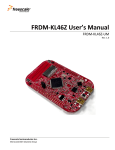
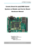
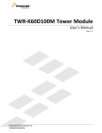
The TWR-KL46Z microcontroller module is designed to work either in standalone mode or as part of the
Freescale Tower System, a modular development platform that enables rapid prototyping and tool re-use
through reconfigurable hardware. Take your design to the next level and begin constructing your Tower
System today by visiting www.freescale.com/tower for additional Tower System microcontroller modules
and compatible peripherals. For TWR-KL46Z specific information and updates visit
www.freescale.com/TWR-KL46Z
Figure 1 Freescale Tower System Overview
TWR-KL46Z48M User’s Manual
Page 3 of 17
2
Contents
The TWR-KL46Z contents include:
TWR-KL46Z board assembly
3ft A to mini-B USB cable for debug interface and power
3ft A to micro-B USB cable for MKL46Z256VLL4 USB interface
Micro-B to A adapter for MKL46Z256VLL4 USB Host applications
Quick Start Guide
TWRPI-sLCD
TWR-KL46Z Features
3
Tower compatible microcontroller module
MKL46Z256VLL4 MCU (48 MHz, 256KB Flash, 32 KB RAM, segment LCD Low power, 100 LQFP package)
Dual role USB interface with Micro-AB USB connector
Touch Tower Plug-in/sLCD Socket
General purpose Tower Plug-in (TWRPI) socket
On-board debug circuit MK20 openSDA serial debug interface with virtual serial port and mass storage device
bootloader
Three axis accelerometer (MMA8451Q)
Four user-controllable LEDs
Two capacitive touch pads
Two (2) user pushbutton switch
Infrared transmit and receive
Potentiometer
GPIO header for prototyping
Potentiometer for ADC measurements
32.768 clock for RTC operation
Power selectable 3.3V/1.8V
TWR-KL46Z48M User’s Manual
Page 4 of 17
4
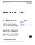
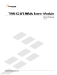
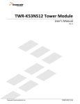
Get to Know the TWR-KL46Z
Touch/sLCD
TWRPI socket
General Purpose
TWRPI
Socket
Reset push
button
VREG input selector
OpenSDA USB
3.3/1.8 VDD select
UART selection
General purpose
GPIO
Touch Sensing
Electrodes and
user’s LEDs
User’s push button
SW3
IR port
KL46 USB Port
Potentiometer
User’s push
button
SW4
User LEDs
5
Reference Documents
KL46 S JTAG
connector
The documents listed below should be referenced for more information on the Kinetis family, Tower System,
and MCU Modules. These can be found in the documentation section of http://www.freescale.com/TWR-KL46Z
or http://www.freescale.com/kinetis
TWR-KL46Z48M_QSG: Quick Start Guide
TWR- KL46Z48M_SCH: Schematics
TWR KL46Z48M_PWB: Design Package
MKL46Z256VLL4 Reference Manual
Tower Configuration Tool
Tower Mechanical Drawing
TWR-KL46Z48M User’s Manual
Page 5 of 17
6
Hardware description
The TWR-KL46Z is a Tower MCU Module featuring the MKL46Z256VLL4—a Kinetis microcontroller with USB 2.0
full-speed OTG controllers in a 64 LQFP package. It is intended for use in the Freescale Tower System but can
operate stand-alone. An on-board debug circuit, OSJTAG, provides a JTAG interface and a power supply input
through a single USB mini-AB connector.
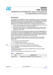
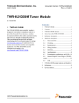
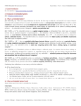
The block diagram of the TWR-KL46Z board is presented in the following figure:
6.1 Block Diagram
Figure 2 Block Diagram of TWR-KL46Z
TWR-KL46Z48M User’s Manual
Page 6 of 17
6.2 Microcontroller
The TWR-KL46Z is a Tower MCU Module featuring the MKL46Z256VLL4 —a Kinetis microcontroller with USB 2.0
full-speed OTG controllers, and segment LCD controller in a 100 LQFP package. It is intended for use in the
Freescale Tower System but can operate stand-alone. An on-board debug circuit, openSDA, provides a SWD
interface and a power supply input through a single USB mini-AB connector, as well as a serial to USB, and CDC
class compliant UART interface.
Table 1 Features of MKL46Z256VLL4
Feature
Description
Ultra low power
-10 low-power modes with power and clock gating for optimal peripheral
activity and recovery times. Stop currents of <190 nA (VLLS0), run currents of
<280 uA/MHz, 4 µs wake-up from Stop mode
-Full memory and analog operation down to 1.71V for extended battery life
-Low-leakage wake-up unit with up to eight internal modules and sixteen pins
as wake-up sources in low-leakage stop (LLS)/very low-leakage stop (VLLS)
modes
-Low-power timer for continual system operation in reduced power states
Flash, SRAM
-256 KB flash featuring fast access times, high reliability, and four levels of
security protection. No user or system intervention to complete programming
and erase functions and full operation down to 1.71V.
-32 KB of SRAM
Mixed-signal capability
- High-speed 12/16-bit analog-to-digital converter (ADC)
- Comparator (CMP) with internal 6-bit digital-to-analog converter (DAC)
- 12-bit digital-to-analog converter (DAC)
TWR-KL46Z48M User’s Manual
Page 7 of 17
Feature
Description
Performance
- 48 MHz ARM Cortex-M0+ core
- Up to four channel DMA for peripheral and memory servicing with reduced
CPU loading and faster system throughput - Cross bar switch enables
concurrent multi-master bus accesses, increasing bus bandwidth Independent flash banks allowing concurrent code execution and firmware
updating with no performance degradation or complex coding routines
- Bit manipulation engine (BME) allows execution of single-instruction atomic
bit-modify-write operations on the peripheral address space
Timing and Control
Human-Machine
Interface
Connectivity and
Communications
Reliability, Safety and
Security
- Low power timers.
- Four-channel 32-bit periodic interrupt timer provides time base for RTOS
task scheduler or trigger source for ADC conversion
-Hardware touch-sensing interface (TSI) with up to 16 inputs
-TSI operates in low power modes (minimum current adder when enabled)
-TSI hardware implementation avoids software polling methods
-High sensitivity level allows use of overlay surfaces up to 5 mm thick.
-segment LCD controller up to 8X47 or 4x51 segments
- Full-Speed USB Device/Host/On-The-Go with device charge detect capability
- Optimized charging current/time for portable USB devices, enabling longer
battery life
- USB low-voltage regulator supplies up to 120 mA off chip at 3.3 volts to
power external components from 5-volt input
- Three UARTs (one UART supports RS232 with flow control, RS485, ISO7816
and IrDA while the other two UARTS support RS232 with flow control and
RS485)
- One Inter-IC Sound (I2S) serial interface for audio system interfacing
- two SPI module
-two I2C module
- Memory protection unit provides memory protection for all masters on the
cross bar switch, increasing software reliability
- Independent-clocked computer operating properly (COP) guards against
clock skew or code runaway for fail-safe applications such as the IEC 60730
safety standard for household appliances
TWR-KL46Z48M User’s Manual
Page 8 of 17
6.3 Clocking
The Kinetis MCUs start up from an internal digitally controlled oscillator (DCO). Software can enable the main
external oscillator (EXTAL0/XTAL0) if desired. The external oscillator/resonator can range from 32.768 KHz up to
a 32 MHz. An 8 MHz crystal is the default external source for the MCG oscillator inputs (XTAL/EXTAL).
A 32.768 KHz oscillato is connected to the RTC clock in input.
6.4 System Power
When installed into a Tower System, the TWR-KL46Z can be powered from either an on-board source or
from another source in the assembled Tower System.
In stand-alone operation, the main power source (5.0V ) for the TWR-KL46Z48Mmodule is derived from
either the openSDA USB mini-B connector or the KL46 USB micro-AB connector (J5). Two low-dropout
regulators provide 3.3V and 1.8V supplies from the 5.0V input voltage. Additionally, the 3.3V regulator built
into the KL46 can be selected to power the 3.3V bus. All the user selectable options can be configured using
two headers, J7 and J3.
6.5 Real Time Clock (RTC)
Y500 is a 32.768 kHz oscillator connected to RTC_CLKIN. By enabling the external clock input option in the
RTC, it can be used as a highly precise time reference..
6.6 Debug Interface
There are two debug interface options provided: the on-board openSDA circuit and an external ARM SWD
connector.
6.6.1 OpenSDA
An on-board MK20-OpenSDA circuit provides an SWD debug interface to the MKL46Z256. A standard USB
A male to mini-B male cable (provided) can be used for debugging via the USB connector, J5. The OpenSDA
interface also provides a USB to serial bridge.
6.6.2 Cortex Debug SWD Connector
The Cortex Debug SWD connector is a standard 2x5-pin (0.05") connector providing an external debugger cable
with access to the SWD interface of the MKL46Z256.
TWR-KL46Z48M User’s Manual
Page 9 of 17
Table 2 Cortex Debug connector
Pin
Function
TWR-KL46Z Connection
1
2
3
4
5
6
7
8
9
10
VTref
SWDIO
GND
SWCLK
GND
NC
NC
NC
NC
nRESET
3.3V MCU supply (MCU_PWR)
PTA3/SCI0_RTS_b/FTM0_CH0/SWD_DIO
GND
PTA0/SCI0_CTS_b/FTM0_CH5 /SWD_CLK
GND
RESET_b
6.7 UART
UART2 can be connected to OpenSDA ot TWR-Elevators through jumpers J10 and J11
J10 UART2_TX_TGTMCU - PTE16/UART2_TX
J11 UART2_RX_TGTMCU - PTE17UART2_RX
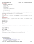
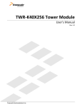
6.8 Infrared Port
An infrared transmit and receive interface is implemented as shown in Figure 5. The UART2_TX pin directly
drives an infrared diode. The receiver uses an infrared phototransistor connected to UART2_RX through a low-
TWR-KL46Z48M User’s Manual
Page 10 of 17
pass filter.
Figure 3 Infrared circuit
6.9 Accelerometer
TWR-KL46Z48M User’s Manual
Page 11 of 17
An MMA8451Q digital accelerometer is connected to the MKL46Z256VLL4 MCU through I2C module, I2C1, and
GPIO/IRQ signals, PTC10 and PTC11. The MMA8451Q is a smart low-power, three-axis capacitive micromachined
accelerometer with 14 bits of resolution. The device can be configured to generate inertial wake-up interrupt
signals from any combination of the configurable embedded functions allowing the MMA8451Q to monitor
events and remain in a low-power mode during periods of inactivity. For more information on the MMA8451Q,
please visit the MMA8451Q Product Summary Page.
6.10 General Purpose Tower Plug-in (TWRPI) Socket
The TWR-KL46Z features a socket (J6 and J1) that can accept a variety of different Tower Plug-in modules
featuring sensors, RF transceivers, and more. The General Purpose TWRPI socket provides access to I2C, SPI,
IRQs, GPIOs, timers, analog conversion signals, TWRPI ID signals, reset, and voltage supplies. The pinout for the
TWRPI Socket is defined Table 1Table 3
Table 3 General Purpose TWRPI socket pinout
J6
Pin
1
2
3
4
5
6
7
8
9
10
11
12
13
14
15
16
17
18
19
20
J1
Pin
Description
5V VCC
3.3 V VCC
GND
3.3V VDDA
VSS (Analog GND)
VSS (Analog GND)
VSS (Analog GND)
ADC: Analog 0
ADC: Analog 1
VSS (Analog GND)
VSS (Analog GND)
ADC: Analog 2
VSS (Analog GND)
VSS (Analog GND)
GND
GND
ADC: TWRPI ID 0
ADC: TWRPI ID 1
GND
Reset
1
2
3
4
5
6
7
8
9
10
11
12
13
14
15
16
17
18
19
20
Description
GND
GND
I2C: SCL
I2C: SDA
GND
GND
GND
GND
SPI: MISO
SPI: MOSI
SPI: SS
SPI: CLK
GND
GND
GPIO: GPIO0/IRQ
GPIO: GPIO1/IRQ
GPIO: GPIO2
GPIO: GPIO3
GPIO: GPIO4/Timer
GPIO: GPIO5/Timer
.
TWR-KL46Z48M User’s Manual
Page 12 of 17
6.11 Potentiometer, Pushbuttons, LEDs
The TWR-KL46Z features two pushbutton switches connected to GPIO/interrupt signals, one pushbutton
connected to the master reset signal, two capacitive touch pad electrodes, four user-controllable LEDs, and a
potentiometer connected to an ADC input signal. Refer to Table 5 “I/O Connectors and Pin Usage Table” for
information about which port pins are connected to these features.
6.12 Touch Interface TWRPI/sLCD
The touch sensing input (TSI) module of the MKL46Z256 MCUs provides capacitive touch sensing detection with
high sensitivity and enhanced robustness. Each TSI pin implements the capacitive measurement of an electrode.
The TWR-KL46Z provides two methods for evaluating the TSI module. There are two electrodes on-board.
Additionally, 12 TSI signals are connected to a Touch Tower Plug-in (TWRPI) socket (J2) that can accept Touch
TWRPI daughter cards that may feature keypads, rotary dials, sliders, etc. Touch connector is also compatible
with TWRPI-SLCD. Table 4 shows TWRPI/TWRPI-sLCD pin-out and corresponding connection to GD-6363P LCD.
Table 4 Touch TWRPI socket pinout
Pin
1
2
3
4
5
6
7
8
9
10
11
12
13
14
15
16
17
18
19
20
KL46
Module
pin
Module
signal
TWRPI
P5V_TRG_USB
V_BRD
Touch_TWRPI_1
LCD_n
LCD_P12 PTB16/TSI0_CH9/UART0_RX
1 COM0
Touch_TWRPI_2
LCD_P13 PTB17/TSI0_CH10
2 COM1
Touch_TWRPI_3
Touch_TWRPI_4
Touch_TWRPI_5
Touch_TWRPI_6
Touch_TWRPI_7
Touch_TWRPI_8
Touch_TWRPI_9
Touch_TWRPI_10
Touch_TWRPI_11
Touch_TWRPI_12
Touch_TWRPI_ID0
Touch_TWRPI_ID1
GND
RST_TGT_MCU
LCD_P14
LCD_P15
LCD_P23
LCD_P0
LCD_P1
LCD_P2
LCD_P3
LCD_P20
LCD_P22
LCD_P24
LCD_P59
LCD_P60
3
4
5
6
7
PTB18/TSI0_CH11
PTB19/TSI0_CH12
PTC3/LLWU_P7/UART1_RX/FTM0_CH2/CLKOUT
PTB0/ADC0_SE8/TSI0_CH0
PTB1/ADC0_SE9/TSI0_CH6
PTB2/ADC0_SE12/TSI0_CH7
PTB3/ADC0_SE13/TSI0_CH8
PTC0/ADC0_SE14/TSI0_CH13
PTC2/ADC0_SE11/TSI0_CH15/I2C1_SDA
PTC4/LLWU_P8/UART1_TX/FTM0_CH3 {
PTE20/ADC0_DP0/ADC0_SE0
PTE21/ADC0_DM0/ADC0_SE4A
8
9
10
11
COM2
COM3
_3A
_S1
_3F
_2A
_2F
_1A
_1F
RST_TGTMCU_B
TWR-KL46Z48M User’s Manual
Page 13 of 17
6.13 USB
The MKL46Z256 features a full-speed/low-speed USB module with OTG/Host/Device capability and built-in
transceiver. The TWR-KL46Z routes the USB D+ and D- signals from the KL46Z256 MCU directly to the on-board
USB connector (J5)
A power supply switch with an enable input signal and over-current flag output signal is used to supply power to
the USB connector when the KL46Z256 is operating in host mode.
7
TWR-KL46Z Jumper options
The following is a list of all the jumper options. The default installed jumper settings are shown in bold.
Note: Default Configuration, Board powered by OSJTAG USB, RTC powered by PWR_MCU
Jumper
V_BRD
VREG IN
SELECTOR
MCU_PWR
Jumper
designator
J7
Signal
Jumper Option
V_BRD
J28
J3
VDDA_HDR
VREG IN SELECTOR
DEF: 1-3 VBRD 3.3V
1-5 VBRD 1.8V
DEF: 1-2 VDDA to MCU_PWR
DEF: 1-2 Regulator powered by
OpenSDA
2-3 Regulator powered by TWR elevator
J27
MCU_PWR
DEF: 1-2
You can use this jumper for Idd
measurements
TWR-KL46Z48M User’s Manual
Page 14 of 17
Table 5 Connectors and Pin Usage
Module
USB
IRDA
Potentiometer
Accelerometer
GPIO Header
Jumper
Designator
J20
J21
SW3(6-3)
name
Options
Signal
KL46 USN ENA
KL46 USB FLGA
IRDAJ
DEF: 1-2
DEF: 1-2
OFF
SW3(5-4)
CMP0_IN0
OFF
J22
J26
DEF: 1-2
DEF: 1-2
J24
J23
Potentiometer Enable
SDA Accelerometer
Enable
SCL Accelerometer Enable
ACCELEROMETER INT1
PTB11
PTE31
PTE22/ADC0_DP3/ADC0_SE3/U
ART2_TX
PTE23/ADC0_DM3/ADC0_SE7A/
UART2_RX
PTE29/ADC0_SE4B
PTC11/I2C1_SDA
J25
ACCELEROMETER INT2
DEF: OPEN
DEF: 1-2
DEF: OPEN
J9-1
J9-2
J9-3
J9-4
J9-5
J9-6
J9-7
J9-8
J9-9
J9-10
J9-11
PTC10/I2C1_SCL
PTC5/LLWU_P9/SPI0_SCK/CMP0
_OUT
PTC6/LLWU_P10/EXTRG_IN/SPI
0_MISO
PTE20/ADC0_DP0/ADC0_SE0
PTE21/ADC0_DM0/ADC0_SE4A
PTA1/TSI0_CH2/UART0_RX
GND
SWD_DIO_TGTMCU
PTE31/FTM0_CH4
PTB9
PTA2/TSI0_CH3/UART0_TX
PTB11/SPI1_SCK
PTB10/SPI1_PCS0
PTC2/ADC0_SE11/TSI0_CH15/I2
C1_SDA
GND
PTC4/LLWU_P8/UART1_TX/FTM
0_CH3
PTC3/LLWU_P7/UART1_RX/FTM
0_CH2/CLKOUT {
PTC12/FTM_CLKIN0
PTC6/LLWU_P10/EXTRG_IN/SPI
J9-12
J9-13
J9-14
J9-15
J9-16
TWR-KL46Z48M User’s Manual
Page 15 of 17
Module
Jumper
Designator
LEDs
Push Buttons
TSI Electrodes
8
name
Options
Signal
0_MISO
PTC16
PTC13/FTM_CLKIN1
GND
PTC17
PTA17
PTB8/EXTRG_IN
PTE26/TPM0_CH5
PTA16
PTA4
PTC3/LLWU_P7/UART1_RX/FTM
0_CH2/CLKOUT
PTB16/TSI0_CH9
PTB17/TSI0_CH10
J9-17
J9-18
J9-19
J9-20
SW3(1-8)
SW3(2-7)
J13
J15
SW4
SW2
Green LED
Red LED
Orange LED
Yellow LED
Pushbutton1
Pushbutton2
DEF: 1-2
DEF: 1-2
DEF: 1-2
DEF: 1-2
Elec1
Elec2
Electrode1
Electrode2
TSI0_CH10
TSI0_CH9
Useful links
► http://www.freescale.com/TWR-KL46Z
► www.freescale.com
► www.iar.com/freescale
► www.pemicro.com
► www.freescale.com/codewarrior
•
CodeWarrior MCUv10.4
► www.segger.com
TWR-KL46Z48M User’s Manual
Page 16 of 17
Revision History
Revision
1.0
1.1
Date
June, 2013
July, 2013
Description
Initial release for PWA 700-27760 A draft
Update for board Rev C
TWR-KL46Z48M User’s Manual
Page 17 of 17