1
SSA-R2010
SSA-R2020
SSA-R2040
SSA-R2011
SSA-R2021
SSA-R2041
Biometric Reader
user manual
imagine the possibilities
Thank you for purchasing this Samsung product.
To receive more complete service,
please visit our website.
www.samsungsecurity.com
safety information
CAUTION
RISK OF ELECTRIC SHOCK.
DO NOT OPEN
CAUTION: TO REDUCE THE RISK OF ELECTRIC SHOCK, DO NOT REMOVE COVER (OR BACK) NO USER SERVICEABLE
PARTS INSIDE. REFER SERVICING TO QUALIFIED SERVICE PERSONNEL.
This symbol indicates that dangerous voltage consisting a risk of electric shock is
present within this unit.
This exclamation point symbol is intended to alert the user to the presence of
important operating and maintenance (servicing) instructions in the literature
accompanying the appliance.
WARNING
• To reduce the risk of fire or electric shock, do not expose this appliance to rain or moisture.
WARNING
1. Be sure to use only the standard adapter that is specified in the specification sheet.
Using any other adapter could cause fire, electrical shock, or damage to the product.
2. Incorrectly connecting the power supply or replacing battery may cause explosion, fire, electric shock, or damage to
the product.
3. Do not connect multiple controllers to a single adapter. Exceeding the capacity may cause abnormal heat generation or fire.
4. Securely plug the power cord into the power receptacle. Insecure connection may cause fire.
5. When installing the controller, fasten it securely and firmly. The fall of controller may cause personal injury.
6. Do not place conductive objects (e.g. screwdrivers, coins, metal parts, etc.) or containers filled with water on top of the
controller. Doing so may cause personal injury due to fire, electric shock, or falling objects.
7. Do not install the unit in humid, dusty, or sooty locations. Doing so may cause fire or electric shock.
8. If any unusual smells or smoke come from the unit, stop using the product. In such case, immediately disconnect the
power source and contact the service center. Continued use in such a condition may cause fire or electric shock.
9. If this product fails to operate normally, contact the nearest service center. Never disassemble or modify this product in
any way. (SAMSUNG is not liable for problems caused by unauthorized modifications or attempted repair.)
10.. When cleaning, do not spray water directly onto parts of the product. Doing so may cause fire or electric shock.
CAUTION
1. Do not drop objects on the product or apply strong blows to it. Keep away from a location subject to excessive
vibration or magnetic interference.
2. Do not install in a location subject to high temperature (over 50°C), low temperature (below 0°C), or high humidity.
Doing so may cause fire or electric shock.
3. If you want to relocate the already installed product, be sure to turn off the power and then move or reinstall it.
4. Remove the power plug from the outlet when there is a lighting storm. Neglecting to do so may cause fire or damage
to the product.
2_ safety information
5. Keep out of direct sunlight and heat radiation sources. It may cause fire.
6. Install it in a place with good ventilation.
7. Avoid aiming the controller directly towards extremely bright objects such as sun.
8. Apparatus shall not be exposed to dripping or splashing and no objects filled with liquids, such as vases, shall be
placed on the apparatus.
9. The Mains plug is used as a disconnect device and shall stay readily operable at any time.
FCC Statement
1) This device may not cause harmful interference, and
2) This device must accept any interference received including interference that may cause undesired operation.
Caution
This equipment has been tested and found to comply with the limits for a Class A digital device, pursuant to part
15 of FCC Rules. These limits are designed to provide reasonable protection against harmful interference when
the equipment is operated in a commercial environment.
This equipment generates, uses, and can radiate radio frequency energy and, if not installed and used in accordance with the instruction manual, may cause harmful interference to radio communications. Operation of this
equipment in a residential area is likely to cause harmful interference in which case the user will be required to
correct the interference at his own expense.
IMPORTANT SAFETY INSTRUCTIONS
1. Read these instructions.
2. Keep these instructions.
3. Heed all warnings.
4. Follow all instructions.
5. Do not use this apparatus near water.
6. Clean only with dry cloth.
7. Do not block any ventilation openings. Install in accordance with the manufacturer’s instructions.
8. Do not install near any heat sources such as radiators, heat registers, or other apparatus (including amplifiers) that
produce heat.
9. Do not defeat the safety purpose of the polarized or grounding-type plug. A polarized plug has two blades with one
wider than the other. A grounding type plug has two blades and a third grounding prong. The wide blade or the third
prong is provided for your safety. If the provided plug does not fit into your outlet, consult an electrician for
replacement of the obsolete outlet.
10. Protect the power cord from being walked on or pinched particularly at plugs, convenience receptacles, and the
point where they exit from the apparatus.
11. Only use attachments/accessories specified by the manufacturer.
12. Use only with cart, stand, tripod, bracket, or table specified by the manufacturer, or sold with
the apparatus.
13. Unplug this apparatus when a card is used. Use caution when moving the cart/ apparatus
combination to avoid injury from tip-over.
14. Refer all servicing to qualified service personnel. Servicing is required when the apparatus has
been damaged in any way, such as powersupply cord or plug is damaged, liquid has been spilled or objects have
fallen into the apparatus, the apparatus has been exposed to rain or moisture, does not operate normally, or has
been dropped.
English English _ 3
SAFETY INFORMATION
This device complies with part 15 of the FCC Rules. Operation is subject to the following two conditions :
contents
PRODUCT INTRODUCTION
5
INSTALLATION AND EXTERNAL
CONNECTION
11
INITIALIZATION
20
Features
What’s included
At a Glance
Cable Color Scheme
Cable Selection
11
11
12
13
16
17
Installing the Wall Mount
Termination Resistor
Earth-grounding the communication cables
I/O Connection
Connecting to the external reader
Communication Line Connection
20
21
Initializing the system using the DIP switch
Display and Operation Status of Reader/
Register
To register/delete the master ID (card)
Communication Address Setup
Reader Mode and Authentication
22
22
23
25
Registering the ID
To register the ID card along with the
fingerprint
To delete ID
OUTPUT FORMAT
26
WIEGAND Output (Default)
OTHER INFORMATION
27
How to register the fingerprint
TROUBLESHOOTING
28
TroubleShooting
28
30
30
Product Specifications
USER MANAGEMENT
24
26
27
PRODUCT SPECIFICATIONS
4_ contents
5
6
7
9
10
24
24
product introduction
FEATURES
Reader Mode
RF Only Mode
- As soon as the card is authenticated, the corresponding card ID will be transferred to the controller.
RF+FINGER Mode
- As soon as the fingerprint is authenticated, the corresponding card ID will be transferred to the controller.
- For a person whose fingerprint is not registered, the product will automatically switch to RF Only mode.
Error Signal Output
If the product fails to authenticate a fingerprint or unregistered card, it will produce an error signal for 500 ms.
(However, if set to the Wiegand output format) The output format is of the open collector.
Output Format of Card Number
When a fingerprint is authenticated, the corresponding card number will be transferred in 26bit/34bit Wiegand.
Master Card
Used to switch between registration/deletion mode and reader mode.
Switching Operation Mode by External Input
This product can switch between RF Only and RF +Finger, according to the input setting of the product’s
system mode control line (gray with red stripes).
Card Number Input Format
The user ID read by the external reader or using the card or keypad will be transferred in 26bit Wiegand/34bit
Wiegand.
Englis_ English _ 5
PRODUCT INTRODUCTION
This product is a fingerprint recognition reader that is compatible with the proximity reader. This product can be
synchronized with the controller, and is featured by reliable fingerprint recognition, all of which enables you to perform a
high level management of security and time and attendance. Integrated with the proximity reader and the fingerprint
recognition functions, this product will allow access to a user only if the card number matches the fingerprint of the user.
Easily installed on a doorframe or a flat wall (simply replace the existing reader, if any), this product gives you high
satisfaction apart from the elegant looking appearance. The product’s reliable fingerprint recognition will keep you safe
from unauthorized access.
product introduction
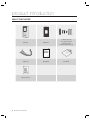
WHAT’S INCLUDED
Check if the following items are included in the product package.
Main Unit
Wall Mount
3 x 30mm Screws (x2)
3.5 x 12mm Screws (x2)
3 x 6mm Screw (x1)
6 x 30mm Plastic Anchors (x2)
xGn
Cables (x4)
tGj
Master Card (x1)
6_ product introduction
Quick Guide
CD Manual
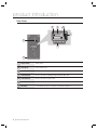
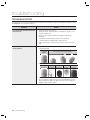
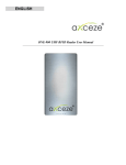
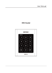
AT A GLANCE
Front Panel
PRODUCT INTRODUCTION
LED
Displays the status of the system operation.
Fingerprint Sensor
Fingerprint scanner module.
Card Recognition
Present a card to the marked area, and the product starts reading it.
Speaker
Sounds a voice comment according to the user manipulation.
Englis_ English _ 7
product introduction
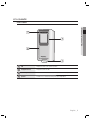
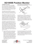
Rear Panel
3
4
5
6
7
2
1
Tamper Switch
Tamper switch.
2
Fixing Screw
Hole for a fixing screw.
3
6-PIN Connector
Can be connected to the Wiegand input and RS-485 communication cables.
4
8-PIN Connector
Can be connected to the Wiegand output and signal output cables.
5
2-PIN Connector
Can be connected to the power cable.
6
RJ45 Connector
Used in TCP/IP communications.
7
DIP Switch
Used to initialize the system or specify the communication addresses.
8_ product introduction
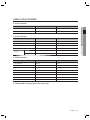
CABLE COLOR SCHEME
❖ 2-PIN Connector
I/O Pins
Signal
Cable Color
DC +12V
Red
Earth-grounding
GND (-)
Black
❖ 6-PIN Connector
I/O Pins
Signal
Cable Color
EX Input Wiegand DATA0
EX-DATA0
Pink
EX Input Wiegand DATA1
EX-DATA1
Sky Blue
NC
Brown
NC
Blue
RS-485 A(+)
RS-485 A(+)
Yellow
RS-485 B(-)
RS-485 B(-)
Gray
RS-485
❖ 8-PIN Connector
I/O Pins
Signal
Cable Color
Wiegand DATA 0
DATA-0
Green
Wiegand DATA 1
DATA-1
White
ERROR SIGNAL OUT
ERROR SIGNAL OUT
Orange
OK SIGNAL OUT
OK SIGNAL OUT
Orange with Black Stripes
TAMPER OUT
TAMPER OUT
Purple
EX_LED_CONTROL
EX_LED_CONTROL
Blue with White Stripes
EX_BUZZER_CONTROL
EX_BUZZER_CONTROL
White with Red Stripes
EX_SYS_CHANGE_IN
EX_SYS_CHANGE_IN
Gray with Red Stripes
❖ TCP/IP (8PIN Connector) RJ45 cable connected
Englis_ English _ 9
PRODUCT INTRODUCTION
Power (+12V)
product introduction
CABLE SELECTION
Item
1
Power (DC12V)
DC Power Product
Wiegand I/O
2
3
Cable Type
Belden #9409, 18 AWG 2 Conductor, Unshielded
Belden #9512, 22 AWG 4 Conductor, Shielded
Product Controller connected
External Reader Product
Belden #9514, 22 AWG 8 Conductor, Shielded
Signal I/O
Belden #9512, 22 AWG 4 Conductor, Shielded
Controller Product
Belden #9514, 22 AWG 8 Conductor, Shielded
RS-485 Cable
4
Converter Host PC
Converter Product
10_ product introduction
Belden #9829, 24 AWG 2-twisted pair, Shielded
installation and external connection
INSTALLING THE WALL MOUNT
1. Use 2 screws to fix the Wall Mount on an appropriate point.
2. Drill a hole on the center of the Wall Mount so that the cables are arranged through it.
127.0
85.0
60.0
48.0
4. Connect the cables to the 4 connectors as appropriate, and use one screw to fix the Wall Mount with the
product.
3-Ø4.5
64.0
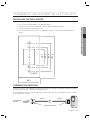
TERMINATION RESISTOR
A resistor is inserted for line’s impedance matching to prevent distortion and reduction in RS-422 or RS-485 long distance
data communications, which is referred to as termination resistor.
Note that termination resistors of lower than 90 are not allowed, neither more than one termination resistor is accepted
for the communications system.
"
RS-485
A
RS-485
RS-485/RS-232
Converter
#
120Ω
120
B
Termination Resistors
Englis_ English _ 11
INSTALLATION AND EXTERNAL CONNECTION
3. Take out the cables through the center hole.
installation and external connection
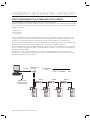
EARTH-GROUNDING THE COMMUNICATION CABLES
It is recommended to use a proper grounding system for the communication cables.
The best grounding method is to earth-ground the shield wire of the communication cable. However, the earth-grounding
of the communication cable is not easy, and it also causes an increased installation cost. There are three grounding points
available for installation:
1. Earth Ground
2. Chassis Ground
3. Power Ground
The most important thing about the earth-grounding does not lie in connecting either end of the shield wire to the
grounding system; This will cause a current flow through the shield wire when the voltage level of both ends of the
shield wire is not equal and this current flow will introduce some noise and interference to communications.
It is recommended to connect ONLY one end of the shield wire of the communication cable to the grounding system.
If you can locate an earth-grounding point nearby, connect one end of the shield wire to that point.
If you could hardly locate an earth grounding point nearby, connect one end of the shield wire to the chassis ground
point. If you could locate neither of an earth or chassis grounding point nearby, connect one end of the shield wire to
the power ground point (GND).
Note that if the chassis ground is not properly connected to the earth and floated from the ground level, then
grounding to the chassis ground will yield the worst communication performance. If this is the case, use the power
ground point rather than the chassis ground.
RS-232
RS-485/RS-232
Converter
Communication
Wires
Connect
ShieldWire
Open
HOST PC
RS-485
RS-485
RS-485
Earth Ground
or Chasis Ground
or Power Ground
GND
12_ installation and external connection
GND
GND
GND
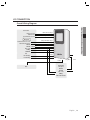
I/O CONNECTION
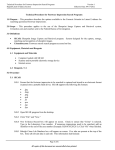
Overall Wiring Diagram
INSTALLATION AND EXTERNAL CONNECTION
Controller
Buzzer Control
LED Control
System Mode Control
White with red stripes
Blue with white stripes
Gray with red stripes
Wiegand
Authentication Success
Authentication Error
DATA1
DATA0
DC + 12V
GND(-)
TAMPER
CLK
DATA
Orange with black stripes
Orange
White
Green
Red
Black
Purple
PC
RS-485-A(+)
RS-485-B(-)
Yellow
Gray
Sky Blue
RJ45
Hub
Pink
26bit/34bit
Wiegand
DATA1
DATA0
DC + 12V
GND(-)
External Reader
Englis_ English _ 13
installation and external connection
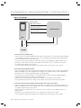
Input Connection
Buzzer Control
(White with red stripes)
LED Control
(Blue with white stripes)
System Mode Control
(Gray with red stripes)
12V
CONTROLLER
GND
POWER
- Connection of External LED control
Connect the LED control input line (blue with white stripes) to the NO port of the controller relay output, and GND
to the COM port. Set I/O of the controller; now you can control turning on/off the green indicator. While the LED
control is working, the green indicator stays solid.
The controller can use the I/O settings to set the LED controller so that it displays the additional LED status for
authorized or unauthorized access upon user authentication. Furthermore, you can handle various situations
according to the I/O settings of the controller.
For more information about the I/O settings of the controller, refer to the user manual of the controller.
- Connection of External Buzzer Control
Connect the buzzer control input line (white with red stripes) to the NO port of the controller relay output, and
GND to the COM port. You can configure the I/O settings of the controller so that it sounds a beep. While
the buzzer control is working, the product keeps sounding the beep.
The controller can use the I/O settings to set the buzzer control so that it sounds an additional beep for
authorized or unauthorized access upon user authentication.
Furthermore, you can handle various situations according to the I/O settings of the controller.
For more information about the I/O settings of the controller, refer to the user manual of the controller.
- Connection of External System Mode Control (switching mode using external input)
Connect the system mode control line (gray with red stripes) to the NO port of the controller relay output, and
GND to the COM port. Set I/O of the controller; now you can control the system mode. While the system mode is
controlled, the product works in RF only mode.
With the I/O or time schedule settings, the controller can control to switch the system operation mode for a
specific timeline.
Furthermore, you can handle various situations according to the I/O settings of the controller.
For more information about the I/O settings of the controller, refer to the user manual of the controller.
14_ installation and external connection
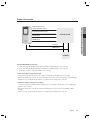
Output Connection
Authentication Error (orange)
CONTROLLER
DATA1 (white)
DATA0 (green)
12V (red)
GND (black)
POWER
- Wiegand DATA Output Connection
1. Connect the green line (Wiegand DATA 0) of the product to Wiegand DATA 0 of the controller.
2. Connect the white line (Wiegand DATA 1) of the product to Wiegand DATA 1 of the controller.
3. The product should be connected to GND(-) of the controller.
- Connection of Authentication Error Signal
Connect the orange line (authentication error signal) of the product to the input port of the controller.
With the I/O settings, the controller can transfer the authentication error event to the operating software program.
Furthermore, you can handle various situations according to the I/O settings of the controller.
- Connection of Authentication Success Signal
Connect the orange line with black stripes (authentication success signal) of the product to the corresponding
input port of the controller.
With the I/O settings, the controller can transfer the authentication success event to the operating software
program.
Furthermore, you can handle various situations according to the I/O settings of the controller.
Englis_ English _ 15
INSTALLATION AND EXTERNAL CONNECTION
Authentication Success
(orange with black stripes)
installation and external connection
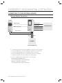
CONNECTING TO THE EXTERNAL READER
External Reader Connection
Reader
DATA-0 (pink)
OK Signal Out
Wiegand D0
Wiegand D1
DATA-1 (sky blue)
Error Signal Out
DC12V (red)
GND (black)
GND
(-)
DC12V
(+)
POWER
Power Supply Unit
1. Connect the DC 12V(+) line of the power supply unit to the plus (+) line of the reader.
2. Connect the GND(-) line of the power supply unit to the minus (-) line of the reader.
3. Connect the Wiegand DATA-0 line of the proximity reader to the pink line.
4. Connect the Wiegand DATA-1 line 1 of the proximity reader to the sky blue line
5. The product should be connected to GND(-) of the external reader.
• For a list of compliant readers (external readers), see the followings:
SSA-R2010/SSA-R2020/SSA-R2040
- Standard 26bit Wiegand format proximity reader
SSA-R2011 / SSA-R2021 / SSA-R2041
- Standard 34bit Wiegand format proximity reader
16_ installation and external connection
CONTROLLER
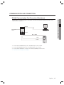
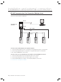
COMMUNICATION LINE CONNECTION
RS-485 Communication Port Connection (Standalone)
RS-232
RS-485/RS-232 Converter
Host PC
AB
RS-485
Max. 1200m
Gray
Yellow
1. Connect the yellow RS485-RTX (+) line to the RS485-A port of the converter.
2. Connect the gray RS485-RTX (-) line to the RS485-B port of the converter.
3. Connect the RS-485/RS-232 converter to the serial port (COM port) of the host PC.
4. Install and launch the application (SAMS).
Englis_ English _ 17
INSTALLATION AND EXTERNAL CONNECTION
A RS485/RS232 converter is needed to make RS485 communications between the product and the host PC.
Please follow the steps below:
installation and external connection
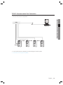
RS-485 Communication Port Connection (Multiple Units)
A RS-485/RS-232 converter is needed to make RS-485 communications across a multiple of the products and
the host PC. Please follow the steps below:
RS-232
RS-485/RS-232
Converter
AB
Host PC
RS-485
Max. 1200m
Gray
Yellow
- You must connect all RS-485 ports of the product in parallel.
1. Connect the yellow RS-485-A (+) line of one product to the yellow RS-485-A(+) line of other product.
2. Connect the gray RS-485-B(-) line of one product to the gray RS-485-B(-) line of other product.
3. Set a unique COMM ADDR for each product.
- You must connect one of the RS-485 ports of the product to the RS-485/RS-232 converter.
1. Connect the yellow RS-485-A(+) line to the RS-485-A port of the converter.
2. Connect the gray RS-485-B (-) line to the RS-485-B port of the converter.
3. Connect the RS-485/RS-232 converter to the serial port (COM port) of the host PC.
4. Install and launch the application (SAMS).
18_ installation and external connection
TCP/IP Communication Port Connection
To enable TCP/IP communications with the host PC, you must have connected the RJ45 jack to CON4 (8-PIN
connector). Please follow the steps below:
Host PC
RJ45
RJ45
RJ45
RJ45
1. Connect the RJ45 jack of the product to the RJ45 plug of the network system.
2. Install and launch the application (SAMS).
Englis_ English _ 19
INSTALLATION AND EXTERNAL CONNECTION
Hub
Initialization
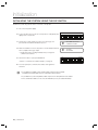
INITIALIZING THE SYSTEM USING THE DIP SWITCH
Initialize the system using the DIP switch on the rear of the product.
1. Disconnect the power supply.
2. Position the DIP switch on the rear of the product to ON (upside) and
apply power to the product.
KSD82H
ON
1
2
3
4
5
6
7
3. The product sounds a beep once with a voice message, and
proceed with the hardware initialization process.
Q
WELCOME TO ACCESS
4. When the initialization is done, the product sounds a beep three times
with a completion message output.
Q
SYSTEM
• The product keeps sounding the beep until you change the
communication address.
5. Use the DIP switch to specify the BOARD ID.
• Refer to “Communication Address Setup”. (on page 22)
CONTROL SYSTEM
INITIALIZING
KSD82H
ON
1
2
3
4
6. You must specify the communication address and register the
master ID.
J
If you initialize the hardware system, all data settings return to the factory default.
(including IDs, fingerprint data, master ID, card number output format, IP)
If you initialize the system using SAMS, all data except for the IP setting will return to the default.
If the communication address is set to 255, the initialization process gets started immediately.
20_ initialization
8
5
6
7
8
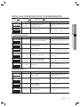
DISPLAY AND OPERATION STATUS OF READER/REGISTER
LED
ON::
LED ON
LED OFF :
LED
LED
LED Blinking
Blinking ::
Beep
PWR OK ERR
ERR
PWR
WELCOME TO ACCESS
CONTROL SYSTEM
PWR OK
OK ERR
PWR
ERR
X
SYSTEM INITIALIZED
Description
The product is in the boot process after it
turned on.
Restores registered user cards and other
system settings to the default.
❖ REGISTRATION MODE
LED
ERR
PWR
PWR OK
OK ERR
Beep
Voice Message
Description
X
MASTER ID REGISTRATION MODE
The first card read by the product after it is
Initialized will be registered as the master
card.
X
REGISTRATION AND DELETION MODE,
SCAN YOUR CARD
You can register or remove the user card.
3 BEEPS
ID REGISTERED
The user card is registered successfully.
3 BEEPS
FINGERPRINT REGISTERED
The user card/fingerprint is registered
successfully.
PWR OK
OK ERR
PWR
ERR
PWR
ERR
PWR OK
OK ERR
PWR OK
OK ERR
PWR
ERR
PWR OK
OK ERR
PWR
2 BEEPS
FINGERPRINT REGISTRATION
FAILED, PLEASE TRY AGAIN
PWR OK
OK ERR
PWR
4 BEEPS
Failed to register the user card/fingerprint.
The user card/fingerprint is deleted
successfully.
ID DELETED
❖ READER MODE
LED
Beep
Voice Message
PWR OK
OK ERR
PWR
X
Description
READER MODE
User card will be authenticated in normal
operation mode
ACCESS GRANTED
User access is granted
PWR OK
OK ERR
PWR
1 BEEP
PWR OK
OK ERR
PWR
2 BEEPS
ACCESS DENIED,
PLEASE TRY AGAIN
User access is denied
PWR OK
OK ERR
PWR
2 BEEPS
ID UNREGISTERED
Unregistered user
Englis_ English _ 21
INITIALIZATION
1 BEEP
Voice Message
initialization
TO REGISTER/DELETE THE MASTER ID (CARD)
The product will switch to Registration mode when presented with the master card in Reader mode.
The product will switch to Reader mode when presented with the master card in Registration mode.
1. If you want to register a new master card, initialize the system before proceeding.
Refer to “Initializing the system using the DIP switch”. (on page 20)
2. When the initialization is completed, the product outputs a voice
message with the green and orange indicators turned on, then
present the master card.
3. When you present the card to the product (beep once when it is
read), it will beep three times with a voice message output.
Q
WELCOME TO ACCESS
CONTROL SYSTEM
Q
MASTER ID
REGISTRATION MODE
Q
REGISTRATION AND
DELETION MODE, SCAN
YOUR CARD
Q
READER MODE
4. The blinking green and orange indicators indicate that the
product switches to Master mode.
• Then, register normal users if you want to.
5. To exit Master mode, present the master card to the product again.
You will hear the following voice message:
• When the green and orange indicators are all turned off, the
product is in Reader mode.
M
For the master card, no fingerprint registration is required.
COMMUNICATION ADDRESS SETUP
You can upload or download the user fingerprint using SAMS. You can also change the settings of the product to apply to
different situations.
The Board ID is a device address based on which the SW application recognizes the device. For this purpose, the Board
ID should be unique.
You can specify up to 255 different BOARD IDs from “000” to “254”.
1. Use the DIP switch on the rear panel to specify the BOARD ID.
2. The DIP switch on the rear panel is assigned in binary code respectively, starting from the leftmost. In other
words, the first DIP switch has the value of “1”, the second one with “2”, and the third is “4”. According to this
way of calculation, the eighth switch has the value of “128”.
3. Move down the DIP switch to OFF, and move it up to the corresponding value.
• The value of the board ID is the sum of all values of the DIP switches whose positions are upward. For instance,
if the first, third, fourth, seventh and eighth DIP switches are positioned upward, the board ID will be “205”.
M
The default address is set to “000”.
For serial communication, each product in the same loop should have a unique communication address.
The default baud rate is set to 57600 bps.
22_ initialization
READER MODE AND AUTHENTICATION
Reader Mode
1. In Reader mode, any recognized user ID or status will be transmitted to the controller.
2. If the user ID and fingerprint are authenticated, the corresponding card ID will be displayed.
How to get authenticated if set to RF Only mode or if registered in RF
Only mode
1. Present the registered card to the reader.
2. When the card is authenticated successfully, you will hear a long beep with the green indicator turned on.
3. The user ID will be displayed according to the specified output format.
How to get authenticated if set to RF+ Finger mode and registered in
RF+ Finger mode
1. Present the registered card to the reader.
2. When the card is recognized, the red lamp on the scanner turns on.
3. Place the registered fingerprint on the scanner.
4. When the fingerprint is authenticated successfully, you will hear a long beep with the green indicator turned on,
and the user ID will be displayed according to the specified output format.
5. If the fingerprint is denied, you will hear a beep twice with the orage indicator blinking twice, and the fingerprint
error signal (Low Active) will be output for 500ms.
If the card is not registered
1. If you will hear a beep twice with the orange indicator blinking twice when presenting the card to the reader, this
indicates that the card is unregistered or already deleted.
2. For an unregistered card or denied fingerprint, the reader will output the fingerprint error signal (Low Active) for
500ms.
Englis_ English _ 23
INITIALIZATION
3. If they are not authenticated, an error signal will be output.
User Management
REGISTERING THE ID
1. Check if the green and orange indicators are all turned off when the reader turns on.
2. Present the master card to the reader. You will hear the following
voice message with the green and orange indicators blinking.
3. Present a user card to the reader. (You will hear a beep once when
the card is read) if you want to register the card alone, do not register
the fingerprint yet and just wait after a voice message of “PUT YOUR
FINGER”.
• You will hear a voice message of “ID Registered” with a beep three
times before registration of the card ID is completed .
Q
REGISTRATION AND
DELETION MODE, SCAN
YOUR CARD
Q
PUT YOUR FINGER
Q
ID REGISTERED
4. Repeat step 3 above if you want to register another user.
5. When the user registration is completed, present the master card to exit the registration mode.
TO REGISTER THE ID CARD ALONG WITH THE FINGERPRINT
1. Check if the green and orange indicators are all turned off when the reader turns on.
2. Present the master card to the reader. You will hear the following
voice message with the green and orange indicators blinking.
3. Present a user card to the reader. Upon the voice message of “PUT
YOUR FINGER”, Place the fingerprint on the scanner.
4. Upon the voice message of “REMOVED FINGER”, release the
fingerprint from the scanner; present the fingerprint on the scanner
again when hearing “PUT YOUR FINGER AGAIN”.
5. The user registration is completed when you hear the corresponding
message with a beep twice.
6. Repeat steps 3 through 5 above if you want to register another user.
7. When the user registration is completed, present the master card to exit
the registration mode.
24_ user management
Q
REGISTRATION AND
DELETION MODE, SCAN
YOUR CARD
Q
PUT YOUR FINGER
Q
REMOVED FINGER
Q
PUT YOUR FINGER AGAIN
Q
FINGERPRINT REGISTERED
TO DELETE ID
1. Check if the green and orange indicators are all turned off when the reader turns on.
3. Present a registered user card to the reader. When you hear the
following message with a beep four times, the user is deleted
successfully.
• When the ID is deleted, the fingerprint data will be deleted too.
Q
REGISTRATION AND
DELETION MODE, SCAN
YOUR CARD
Q
ID DELETED
4. Repeat step 3 above if you want to delete another user.
5. When the ID deletion is completed, present the master card to exit the registration mode.
Englis_ English _ 25
USER MANAGEMENT
2. Present the master card to the reader. You will hear the following
voice message with the green and orange indicators blinking.
Output Format
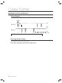
WIEGAND OUTPUT (DEFAULT)
Timing Diagram
100us
5V
1ms
DATA-0
0V
5V
DATA-1
LOGIC
1
2
3
n-2
n-1
n
0
1
1
1
0
0
Data Type (26-bit /34-bit)
• Even parity bits from Bit 2 to Bit 13 / Bit 2 to Bit 17
• Bit 2 to Bit25 / Bit 2 to Bit33 : 3-byte ID number / 4-byte ID number
• Bit 26 / Bit 34 : Odd parity bits from Bit 14 to Bit 25 / Bit 18 to Bit 33
26_ output format
0V
*n : 34 or 26
Other Information
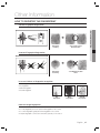
HOW TO REGISTER THE FINGERPRINT
Correct Fingerprint Registration
Fingerprint
scanning
{
Successful 1:1/1:N
Authentication
Incorrect Fingerprint Registration
Fingerprint
Scanning
±
1:1/1:N Authentication
Error
In case of failures of fingerprint recognition
•
•
•
•
Moist Fingerprint
Dry Fingerprint
Stained Fingerprint
Scarred Fingerprint
Dry
Fingerprint
Moist
Fingerprint
Stained
Fingerprint
How to manage fingerprints
Follow the instructions below to increase the rate of successful authentication of the fingerprint.
• For a dry fingerprint, put force to present the fingerprint to the scanner.
• For a moist fingerprint, gently present the fingerprint to the scanner.
• Keep the fingerprint scanner clean all the time, especially on the surface.
Englis_ English _ 27
OTHER INFORMATION
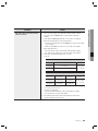
troubleshooting
TROUBLESHOOTING
If the product does not function properly, please see the below for trouble shooting. If the trouble persists, please contact
the SAMSUNG Customer Service near you.
Problem
Action
If you fail to enter registration mode using
the master card
1)
Fingerprint registration or authentication
do not work well.
1)
Check if the master card is invalid.
Change the master card using software communications, and try to access
using the changed card.
2) Refer to the user manual and initialize the hardware. (before system
installation)
* Note that all existing settings will return to the factory default.
(card deleted/system initialized/master card deleted, etc)
3) If the problem persists, contact the nearest customer service for technical
help.
Please check the correct fingerprint registration instruction in the user
manual and try again.
Proper
fingerprint
position
2)
Check the state of the fingerprint.
Normal
fingerprint
3)
28_ troubleshooting
Improperly positioned fingerprints
Dry
Fingerprint
Moist
Fingerprint
Too gentle
pressure
Too string
pressure
Adaptive mode will correct excessively dry or moist fingerprints as necessary
when sensing them. It may take longer to sense the fingerprint in this mode,
but the fingerprint recognition rate will be increased. You can configure the
Adaptive settings using the software.
Problem
1)
Please check the settings of the application software and the controller.
- Check if the product COMM ADDR is recognized by the application
software.
- Set the different COMM ADDR when two or more devices are installed.
- Check the followings when in serial communications.
• Check if the communication speed (57600bps) is the same as the setting
on the software.
• Make sure that COM port of the PC is set correctly on the software.
- When using TCP/IP RJ45
• Check the values of the IP, subnet mask, gateway and port number.
• For details on the settings, refer to the user manual of the software.
2) Check if the communication wiring is done correctly.
- For RS-485
RS-485 (Single)
This product
RS-485/RS-232 Converter
PC
RS-485-A(+)
RS-485-A(+)
RS-485-B(-)
RS-485-B(-)
RS-232 cable
of the converter
RS-485(Multi Drop)
This product
This product
RS-485/RS-232
Converter
RS-485-A(+)
RS-485-A(+)
RS-485-A(+)
RS-485-B(-)
RS-485-B(-)
RS-485-B(-)
PC
RS-232 cable
of the converter
If the multi-drop communication doesn’t work, test the communication settings one by
one in sequence from the first one.
- For TCP/IP communication
• Check if the link LED indicator on the rear panel flickers normally.
• If it doesn’t flicker, check the cable wiring.
3) If the problem persists after you have followed the procedures above,
contact a designated customer service.
Englis_ English
English__29
29
TROUBLE SHOOTING
My reader does not communicate
with the host PC.
Action
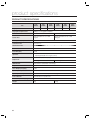
product specifications
PRODUCT SPECIFICATIONS
Item
SSAR2010
SSAR2020
SSAR2040
SSAR2011
SSAR2021
SSAR2041
Fingerprint Users
1,000
Fingerprint Templates Size
800Bytes for 2 Fingerprint Templates
Power / Current
DC 12V / Max.290mA
DC 12V / Max.310mA
Reader Port
External Reader Port 1ea : 26bit
Wiegand
External Reader Port 1ea : 34bit
Wiegand
Reading Time (Card)
30ms
Verification Time
Less than 1sec.
Identification Time
Less than 2sec.
Communication
RS232, RS485, TCP/IP
Baud Rate(bps)
57,600
Input Port
3 EA (External LED Control, External Buzzer Control,
Operating Mode(RF/ RF+ Finger) Control)
2,000
4,000
1,000
2,000
2EA (Error- Output, OK-Output(Open Collector Output))
Output Port
26bit Wiegand
34bit Wiegand
LED Indicator
3 LED Indicators (Red, Green and Orange)
Beeper
Piezo Buzzer
Voice Output (Language)
English
Operating Temperature
0°C to +50°C
Operating Humidity
10% to 90% relative humidity non-condensing
Color / Material
Silver with Black / Polycarbonate
Dimension (W x H x D(mm))
65.0 x 128.0 x 48.5
Weight
240g
30
230g
4,000
Correct Disposal of This Product (Waste Electrical & Electronic Equipment)
(Applicable in the European Union and other European countries with separate collection systems)
This marking on the product, accessories or literature indicates that the product and its electronic accessories (e.g.
charger, headset, USB cable) should not be disposed of with other household waste at the end of their working life. To
prevent possible harm to the environment or human health from uncontrolled waste disposal, please separate these
items from other types of waste and recycle them responsibly to promote the sustainable reuse of material resources.
Household users should contact either the retailer where they purchased this product, or their local government office, for
details of where and how they can take these items for environmentally safe recycling.
Business users should contact their supplier and check the terms and conditions of the purchase contract.
This product and its electronic accessories should not be mixed with other commercial wastes for disposal.
Correct disposal of batteries in this product
(Applicable in the European Union and other European countries with separate battery return systems.)
This marking on the battery, manual or packaging indicates that the batteries in this product should not be disposed of
with other household waste at the end of their working life. Where marked, the chemical symbols Hg, Cd or Pb indicate
that the battery contains mercury, cadmium or lead above the reference levels in EC Directive 2006/66. If batteries are
not properly disposed of, these substances can cause harm to human health or the environment.
To protect natural resources and to promote material reuse, please separate batteries from other types of waste and
recycle them through your local, free battery return system.
AB82-02555A