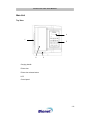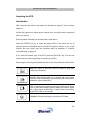
1
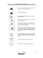
CardioCare 2000 User Manual
CardioCare 2000
OPERATION
MANUAL
Bionet America, Inc.
Operation Manual for CardioCare 2000 version 1.0
CardioCare 2000 User Manual
Terms of Warranty .......................................................................................................... 1
How to reach us … ......................................................................................................... 2
Definitions of Warnings, Cautions, and Notes ................................................................ 3
Service Requirements .................................................................................................... 4
General Precautions ....................................................................................................... 5
General Precautions on Electric Safety .......................................................................... 6
Safety Symbols............................................................................................................... 7
General Information ........................................................................................................ 8
Introduction.................................................................................................................. 8
Features of the Equipment .......................................................................................... 8
Equipment Description ................................................................................................ 9
Standard components (Some items might be changed without notice)........................................ 9
Options..................................................................................................................... 9
Main Unit ................................................................................................................... 10
Top View................................................................................................................. 10
Rear View............................................................................................................... 11
Left Side View ........................................................................................................ 11
Right Side View ...................................................................................................... 12
LCD Panel ................................................................................................................. 13
Control Panel............................................................................................................. 14
Indicator lamps....................................................................................................... 14
Short keys .............................................................................................................. 14
AC Power .................................................................................................................. 16
System Installation .................................................................................................... 17
Installation Precautions .......................................................................................... 17
Power Cable Connection........................................................................................... 17
Patient Cable Connection.......................................................................................... 17
Recording Paper Installation ..................................................................................... 17
Menu Structure .......................................................................................................... 18
System Settings ........................................................................................................ 19
Initial Settings......................................................................................................... 19
Date and Time........................................................................................................ 20
Site Identification.................................................................................................... 21
Preparation for Acquiring the ECG ............................................................................... 22
Electrode Positions.................................................................................................... 22
CardioCare 2000 User Manual
Electrode Connections .............................................................................................. 23
Check Connections ................................................................................................ 23
Connecting the Electrodes ..................................................................................... 23
Connecting the Patient Cable.................................................................................... 23
Lead-Off Troubleshooting .......................................................................................... 24
Acquiring the ECG ........................................................................................................ 25
Introduction................................................................................................................ 25
Basic settings ............................................................................................................ 26
General Information ............................................................................................... 26
Signal Level Setting ............................................................................................... 26
Print Speed Setting ................................................................................................ 27
Filter Setting ........................................................................................................... 27
Channel Form Setting ............................................................................................ 28
Rhythm Channel Setting ........................................................................................ 29
Diagnosis Setting ................................................................................................... 29
Grid Setting ............................................................................................................ 30
Enter Patient Data .................................................................................................. 31
Monitor Mode ............................................................................................................ 37
Output Method ....................................................................................................... 37
Output Form ........................................................................................................... 37
Record Mode ............................................................................................................. 38
10 Second ECG Recording.................................................................................... 38
60 Second ECG recording ..................................................................................... 39
Copy Mode ................................................................................................................ 40
Taking Care of the System............................................................................................ 43
Maintenance and Cleaning........................................................................................ 43
Regular Inspection .................................................................................................... 43
Troubleshooting......................................................................................................... 44
Technical Data .............................................................................................................. 45
CardioCare 2000 User Manual
Terms of Warranty
-
This product is manufactured using strict quality control.
-
CardioCare 2000 is warranted by Bionet America, Inc. to be free from
defects in material and workmanship for three years from the date of
purchase.
-
Bionet America, Inc or an Authorized Dealer Service Center will make
warranty repair or replacement at no charge during the warranty period if
properly used under normal conditions in accordance with the instructions
for use.
-
In the event of a malfunction or failure during the warranty period, the
customer should inform Bionet America, Inc. of the model name, serial
number, date of purchase, and an explanation of the defect.
-1-
CardioCare 2000 User Manual
How to reach us …
Service Calls
The following telephone number should be used to contact
Bionet America, Inc.
Product and
Purchase
Inquiries
By dialing one number you can place service calls,
purchase products or make inquiries, or get technical
support.
Supply products
and other
accessories
In the event of a malfunction or failure, contact the
Service Dept. of Bionet America, Inc. and provide the
model name, serial number, date of purchase, and
an explanation of the failure.
Technical
Support
Main office toll free 1-877-924-6638
-2-
CardioCare 2000 User Manual
Definitions of Warnings, Cautions, and Notes
These terms are defined as listed below. Users should operate the equipment
according to all of the Warning and Caution labels.
The manufacturer, Bionet America, Inc., and Authorized Dealers are not responsible
for any damage or breakdown that is caused by misuse or failure to maintain the
equipment.
Warning
Indicates that serious injury or death to the patient, property
damage, or material losses could occur.
Caution
Indicates that this is not life threatening but could lead to
injury.
Note
Indicates that there is no danger, but is important for proper
installation, operation, and maintenance of the equipment.
-3-
CardioCare 2000 User Manual
Service Requirements
Refer servicing of the equipment to Bionet America, Inc. authorized service personnel.
Any attempt to repair the equipment while under warranty will void that warranty.
It is the responsibility of users requiring service to report the need for service to Bionet
America, Inc. or to one of their Authorized Dealers.
Failure to implement a satisfactory maintenance schedule may cause equipment
failure and possible health hazards.
If there are any problems with the equipment, please follow the steps below:
Contact Bionet America, Inc. immediately and furnish the model name,
serial number, date of purchase, and description of the problem.
Try to solve the problem over the phone with the service department
personnel. If the problem cannot be solved over the phone, the machine
can be returned for replacement.
Bionet America, Inc. or its Authorized Dealer will make available, on
request, circuit diagrams, component part lists, descriptions, calibration
instructions or other information which will assist appropriately qualified
technical personnel to repair those parts of equipment which are
designated by Bionet America, Inc. as repairable.
-4-
CardioCare 2000 User Manual
General Precautions
Do not keep or operate the equipment in the environments listed below.
Avoid placing in an
area exposed to
moisture. Do not
touch the equipment
with wet hand s.
Avoid exposure to
direct sunlight
Avoid placing in an
area where there
is a high variation of
temperature.
Operating
temperature
ranges from 50°F
to 104°F. Operating
humidity ranges
from 30% to 85%.
Avoid placing near
an electric heater
Avoid placing in an
area where there
is an excessive
humidity rise or
ventilation problem.
Avoid placing in
an area where
there is an excessive
shock or vibration.
Avoid placing in
an area where
chemicals are
stored or where
there is danger of
gas leakage.
Avoid
contamination of
dust and
especially metal
material into the
equipment.
Do not disassemble
the equipment as
this will void the
warranty.
Turn the power
off when the
equipment is not
being used.
-5-
CardioCare 2000 User Manual
General Precautions on Electric Safety
Check the items listed below before operating the equipment.
Be sure that the AC power supply line is appropriate to use (100 - 240V AC).
Be sure that the patient connection cable of the system is properly attached.
Be sure to use only the power cable supplied.
Note
The equipment should not be placed in the vicinity of electric
generators or broadcasting apparatus to eliminate electric noise.
Otherwise, it may cause an incorrect interpretation.
Using the same power source with other electric instruments may
cause an incorrect interpretation.
Note
The CardioCare 2000 is classified as listed below:
This equipment conforms to Class I, Type-BF. The equipment
should be grounded to protect the patient from electrical shock.
Do not use the equipment near flammable anesthetics or
solvents.
The equipment conforms to Class I according to IEC/EN
60601-1 (Safety of Electric Medical Equipment)
This equipment conforms to Class A according to IEC/EN
60601-1-2 (Electromagnetic Compatibility Requirements)
Note
Accessory equipment connected to the analog and digital
interfaces must be certified according to the respective IEC
standards (e.g. IEC 950 for data processing equipment and IEC
601-1 for medical equipment). Furthermore, all configurations
shall comply with the system standard EN 60601-1-1:1993.
Anyone who connects additional equipment to the signal input or
signal output configures a medical system and is therefore
responsible that the system complies with the requirements of the
system standard IEC 601-1-1:1993. If in doubt, consult the
technical service department or your local representative.
-6-
CardioCare 2000 User Manual
Safety Symbols
The International Electro-technical Commission (IEC) has established a set of
symbols for medical electronic equipment, which classify a connection or warn of any
potential hazards. The classifications and symbols are shown below.
Save these instructions.
Symbols
Contents
Isolated patient connection. (IEC 601-1-Type BF)
Device switched off.
Device switched on.
This symbol identifies a safety note. Ensure you understand the
function of this control before using it. Control function is
described in the appropriate operation manual.
Conductor provides a connection between equipment and the
potential equalization busbar of the electrical installation
External Signal IN/OUT Port
EKG Signal Input Port
The following symbol is used inside the system:
Identifies the point where the system safety ground is fastened
to the chassis. Protective earth is connected to conductive parts
of Class 1 equipment for safety purposes.
-7-
CardioCare 2000 User Manual
General Information
Introduction
The CardioCare 2000 is a multi channel, interpretive ECG machine that acquires and
records a patient’s ECG.
CardioCare 2000 provides users with a record of the patient ECG, measurement
parameters for diagnosis, and auto analysis. Patient information and site identification
is printed with the ECG on the output report and is effective for patient chart control.
For convenient operation, the ECG can be measured and recorded by pressing a
short key (described below). Then, after applying the filter, calculating the
measurement parameters, and auto analysis, the ECG is printed in a letter sized
report form.
In addition to AC power, it can be continuously operated with a built-in rechargeable
battery. This enables convenient portability of the CardioCare 2000.
Features of the Equipment
The CardioCare 2000 ECG can be printed in various channel form of three channel
and 1rhythm, six channel and 1rhythm, 12 channel rhythm, or for 60 seconds and
1rhythm in a letter sized report.
The single channel rhythm is recorded for 60 seconds and printed in a letter-sized
report.
In Monitor Mode, 12 channel rhythms are printed simultaneously and continuously in
real time.
After calculating the measurement parameters such as heart rate, PR interval, QRS
duration, QT/QTc, and P-R-T axes required for diagnosis the ECG report is printed.
-8-
CardioCare 2000 User Manual
Auto analysis assists diagnosis.
For convenient diagnosis, the ECG can be printed after changing system settings
such as filter, signal level, printing speed, channel form, or rhythm channel of the
recorded ECG data.
Equipment Description
Check to insure that all of the listed components are present and that the main unit
and any accessories are not damaged.
The CardioCare 2000 is composed of the following items:
Standard components (Some items might be changed without notice)
CardioCare 2000 Main unit
Patient cable (1 EA)
AC power cable (1 EA)
Disposable Electrodes (1 Pack)
Recording paper (1 roll)
ECG Clips (1 Set)
Rechargeable Battery (1 EA)
Diagnosis Guide Book (1EA)
Operation manual (1EA)
Quick Reference Guide (1 EA)
Warranty Card
Test Report
Instructional CD (1 EA)
Options
Cart
Carrying Bag
Hanger
-9-
CardioCare 2000 User Manual
Main Unit
Top View
4
1
5
2
3
Carrying handle
Printer door
Printer door release button
LCD
Control panel
- 10 -
CardioCare 2000 User Manual
Rear View
1
3
2
4
5
Potential equalization stud
Main power switch
AC power socket
RS-232C SERIAL port
RS45 LAN port
Left Side View
1
Carrying handle
- 11 -
CardioCare 2000 User Manual
Right Side View
1
Patient cable connector port
Warning
To avoid electric shock, DO NOT open the case of the
equipment. Refer servicing to Bionet America, qualified
personnel or your local authorized dealer.
- 12 -
CardioCare 2000 User Manual
LCD Panel
When the power switch is activated, the LCD panel displays the version of the
system software and manufacturer name for two seconds and then the system
status.
Displayed items on the LCD are as follows:
Displays the ECG signal level of 5, 10, 20, or aut (Auto Gain)
Displays the printing speed of 12.5, 25, or 50
Displays if the base line filter setting is on or off
Displays if the EMG filter setting is on or off
Displays the heart rate
Displays the channel form of the output report of 3ch+1rhy, 6ch+1rhy, 12ch
rhy, 60s 1rhy
Displays the rhythm channel setting out of I, II, III, aVR, aVL, aVF, V1, V2, V3,
V4, V5, V6
- 13 -
CardioCare 2000 User Manual
Control Panel
Indicator lamps
READY
When power is applied, this lights for a short time, goes out,
and then lights again. This indicates that the system self
test is complete and the system is ready to be used.
Indicates the level of battery charge in green or amber.
When the battery charge indicator lamp is illuminated
amber, turn the system power off and connect the AC power
source. Then turn the system power on again.
Indicates that AC power is applied.
Short keys
Selects signal level (mm/mV) of 5, 10, 20, or aut
(Auto) (I-aVF: 10, V1-V6: 5)
Selects the printing speed (mm/sec) of 12.5, 25, or
50
Selects whether or not to activate the filter that
eliminates base line drift (on/off)
Selects whether or not to activate the filter that
eliminates EMG (on/off). The ECG signal can be
distorted by applying this filter.
N
This key is reserved for use when network functions
will be added.
- 14 -
CardioCare 2000 User Manual
Selects the channel form of the output report of
3ch+1rhy, 6ch+1rhy, 12ch rhy, 60s 1rhy
Selects the rhythm channel
Shows the menu to enter patient ID, name, age, sex,
height, and weight
Monitor mode. Continuously prints the real-time
ECG from the patient
Records the ECG data for 10 seconds and prints a
letter sized report after calculating the measurement
parameters of the recorded ECG
Prints the same report as previously printed in
record mode or prints after changing system settings
such as filter, signal level, output speed, channel
form, or rhythm channel. Also, allows exit from the
set-up menu
The Command Key. Exit during printing or recording
of ECG data. In addition, displays the set-up screen
and allows selection of menu or select items to
change.
Moves to the next left item in the set-up menu
Moves to the next right item in the set-up menu
- 15 -
CardioCare 2000 User Manual
AC Power
When AC power is supplied to the equipment, the AC power indicator lamp on the
front panel is illuminated and the battery is being charged automatically.
AC power indicator lamp
Battery charge indicator lamp
When not connected to AC power, the machine is operated from battery power. When
the battery is used, the battery charge indicator lamp is illuminated green. When the
battery power is low, a beep tone sounds three times in series and the battery charge
indicator lamp shows amber. In this case, turn the system power off and connect the
AC power source. Then, turn the system power on again. If the battery falls to no
charge, the machine sounds a rapid beeping tone, the battery and ready indicator
lights flash, and the machine turns itself off.
-
Required time for charging – approximately four hours
-
Continuous battery operating time - one hour
Caution
For the protection of the environment, DO NOT discard a
battery. Please inquire as to the proper procedure and dispose
accordingly.
- 16 -
CardioCare 2000 User Manual
System Installation
Installation Precautions
When installing the CardioCare 2000, take the following precautions:
- The equipment should be operated within a temperature range of 50104 ° F and 30-85 humidity.
- Handle the power cord connection and patient cable with care.
- Do not plug several power cords in one electric outlet.
- Main unit should be used on a level space.
- Check that the equipment is properly grounded to avoid interference.
- The entire system settings are stored on the internal memory even when
system power is turned off and on again
- Avoid excessive shock or vibration that could result in equipment
damage.
- Avoid using in areas of dust and flammable material.
Power Cable Connection
The equipment should function normally when connected to power using the supplied
power cord. If the power does not come on when connected to AC and the battery is
charged, contact the service department of Bionet America, Inc.
Patient Cable Connection
Connect the patient cable into the connection port at the side of the equipment.
Connect the ECG clips to the RA, LA, RL, LL, and V1 – V6 wires on the patient cable.
Connect the patient cable to the electrodes on the patient.
Recording Paper Installation
The printer door will open if the printer release button at the side of CardioCare 2000
is pushed to the right. Place the recording paper with the signal-recording side up and
push down on the door to close.
- 17 -
CardioCare 2000 User Manual
Menu Structure
The CardioCare 2000 provides three basic modes of operation: preparation mode,
output mode, and menu mode.
Preparation mode is an initial condition when the system starts. The LCD displays
the system settings and heart rate. This mode also allows system configuration
settings to be changed and for completing the initial setup.
The key that looks like the one to the right is the Command Key.
The system settings can be changed by pressing each of the short keys SENS (1),
SPD (2), BASE (3), MUSC (4), FORM (6), LEAD (7), PAT (8), MON (9), REC (0),
or ESC/COPY on the control panel. The Command Key calls up the menu mode.
Output mode is to activate the print operation by pressing one of the short keys:
MON, REC, COPY. Only the MON, REC, and COPY keys of the control panel will
stop printing in the output mode.
Menu mode is activated by pressing the Command Key and using the window
displays on the LCD.
PAT FLT PRN SYS
< PATient Info >
The top line shows a blinking menu item that is selected and the bottom line shows
the meaning of the abbreviation on the top row of the menu screen.
Press the left arrow
the right arrow key
key to move to the selection to the left. Press
to move to the next selection to the right.
Press the Command Key to select the menu items.
Press the ESC/COPY key of the control panel to step back through the menu
selections.
- 18 -
CardioCare 2000 User Manual
The Menu structure is as follows:
PAT
FLT
PRN
SYS
< PATient Info > Enter the patient information including patient ID,
name, age, sex, height, and weight
< FiLTer setup > Select and adjust the filter settings of a base line drift
filter, EMG filter, AC filter, or LPF (low pass filter).
< PRiNter setup > Select and adjust the signal level, printing speed,
grid on/off, number of channels, rhythm channel select, test print
< SYStem setup > Enter system the settings including date, time, and
hospital or clinic name.
System Settings
Initial Settings
The CardioCare 2000 is initialized at the factory as follows:
Date (DATE)
Time (TIME)
Signal level (SENS)
Display speed (SPD)
Grid (GRID)
Channel form (FORM)
Rhythm lead (LEAD)
Base line filter (BASE)
EMG filer (MUSC)
AC noise filter AC)
Low pass filter (LPF)
2000-03-01
00-00-00
10mm/mV
25mm/s
Off
6ch+1rhy
II
On
Off
60hz
150hz
- 19 -
CardioCare 2000 User Manual
Date and Time
To set the date on the CardioCare 2000, press the Command Key once and move to
the right until SYS begins to blink. Press the Command Key again to select SYS and
DATE will begin to blink. Press the Command Key again and enter the current date.
PAT FLT PRN SYS
< SYStem setup >
DATE TIME HOSP >>
2000-03-01
* DATE SETUP *
2000-03-01
The numbers are entered by pressing 0 through 9 on the numeric keypad in the
current cursor position and the cursor automatically moves to the right after each entry.
To exit the date setting, press the Command Key to return to the previous menu or the
ESC/COPY key to return to the initial screen.
To set the current time on the CardioCare 2000, follow the steps above and move to
TIME SETUP. Enter the time in the same way the date was entered.
- 20 -
CardioCare 2000 User Manual
Site Identification
Site identification is to identify the name of the site that uses the system. To enter
the site name on the CardioCare 2000, press the Command Key once and use the
right arrow key
move to the right until SYS begins to blink. Press the Command
Key again and DATE will begin to blink. Use the right arrow key
to move to
HOSP, press the Command Key again, and enter the site name.
PAT FLT PRN SYS
< SYStem setup >
DATE TIME HOSP >>>
* Enter Hosp. *
_
The site name can be entered using 16 characters or less. To enter the name, select
the characters for the current cursor position. For example, using the “2” key, you can
enter the letters A, B, or C or the number 2. Press the key once and the letter A
appears, press it twice, the letter B appears and so on.
To enter the next character, press the right arrow key
and enter the next character
in the name as above. Continue this process until the name is complete. To exit the
site identification setting, press the Command Key or the ESC/COPY key to return to
the previous menu and the ESC/COPY key to return to the initial screen.
- 21 -
CardioCare 2000 User Manual
Preparation for Acquiring the ECG
Electrode Positions
To record a 12 lead ECG, connect the electrodes to the patient as follows:
(RA)
(RL)
(LA)
(LL)
The electrode positions are as follows:
(RL)
Right leg
(LL)
Left leg
(RA)
Right arm
(LA)
Left arm
V1
Fourth intercostal space at the right border of the sternum
V2
Fourth intercostal space at the left border of sternum
V3
Midway between location V2 and V4
V4
At the mid-clavicular line in the fifth intercostal space
V5
At the frontal axillary line on the same horizontal level as V4
V6
At the central axillary line on the same horizontal level as V4 and V5
- 22 -
CardioCare 2000 User Manual
Electrode Connections
Check Connections
Check the system connections before acquiring the patient’s ECG.
-
Check that there are no mechanical hazards.
-
Check the connection of the external cables.
-
Check the machine to insure that the parameters are set correctly.
Connecting the Electrodes
Have the patient lie comfortably on their back and connect the electrodes as
described in “Electrode Positions” on page 22.
Connecting the Patient Cable
Connect the patient cable to the electrodes and then connect it to the CardioCare
2000. Defibrillation protection is provided only if used with the original Bionet patient
cable.
Warning
Use only electrodes and patient cables provided from
Bionet America, Inc.
- 23 -
CardioCare 2000 User Manual
Lead-Off Troubleshooting
You can determine that the leads are connected properly by using the Monitor mode
output of real time printing (explained later in this manual). A lead off condition can
occur in two ways.
First, the lead comes off the patient. In this case, re-connect the lead.
Second, conductivity between the patient and electrodes is poor. In this case, apply a
new electrode to the patient.
Under very exceptional circumstances, if there continues to be a poor ECG signal,
there could be a problem with the patient cable. Contact service at Bionet America, Inc.
- 24 -
CardioCare 2000 User Manual
Acquiring the ECG
Introduction
After connecting the leads to the patient, as described on page 22, turn the power
switch on.
Set the filter, signal level, display speed, channel form, and rhythm lead as described
later in this section.
Enter the patient information as described later in this section.
Press the OPR/REC (0) key to record the patient’s ECG. If the results are not as
expected, press the WXY/MON key to view the ECG signal in real time. If you are still
troubled with poor signal, take the necessary steps as described in “Lead-Off
Troubleshooting” on page 24.
If you would like another copy of the ECG, press the ESC/COPY key. You can also
press this key to exit during printing or recording of the ECG.
Memorizing the short keys described below makes use of the CardioCare 2000 easier.
MONITOR: Prints a real time ECG for direct or long term
monitoring of the patient.
RECORD: Records ECG data for 10 seconds and prints a letter
sized report with interpretation, after calculating the measurement
parameters of the recorded ECG.
COPY: Prints the same report as previously printed one in record
mode or prints after changing system setting such as filter, signal
level, output speed, channel form, rhythm cannel of previously
recorded ECG data in record mode
COMMAND: Exit during printing or recording of ECG data
- 25 -
CardioCare 2000 User Manual
Basic settings
General Information
When the system is turned on and completes its self test, the LCD displays the current
system settings in the following order: signal level, printing speed, base line filter,
EMG filter, heart rate, channel form, and rhythm channel. These settings can be
changed using two methods: the Short Keys or the Menu. Pressing the Command Key
once will enter menu mode and the LCD displays the various selections that can be
made. PAT is used to enter patient information, FLT is used to select the filter, PRN is
used to configure the print settings, and SYS is used to for the initial system
configuration settings or to modify the system settings.
Signal Level Setting
The signal level should be adjusted so that the signal does not overlap with
neighboring traces or the amplitude of the pulse is too small to interpret.
The signal level setting is adjustable in four ways. The entire 12 channel ECG is set to
5mm/mV, 10mm/mV, 20mm/mV and aut (Auto gain control), which sets I, II, III, aVR,
aVL, aVF to 10mm/mV, and V1, V2, V3, V4, V5, V6 to 5mm/mV. The 5mm/mV setting
indicates that the amplitude of 1mV pulse is amplified into 5mm.
To change the signal level, press the QZ/SENS (1) key and each time it is pressed, it
scrolls to the next available level. The selected setting is shown on the bottom line of
the output report.
- 26 -
CardioCare 2000 User Manual
Print Speed Setting
The print speed setting is to adjust the speed of the printed output. The adjustable
values are 12.5 mm/s, 25 mm/s, or 50 mm/s. For a wider range of signal display, set a
larger value.
To change the printing speed, press the ABC/SPD key and select the desired speed.
The ABC/SPD key toggles among the values 12.5, 25, or 50. The selected setting is
shown on the bottom line of the output form.
Filter Setting
Any AC power noise, base line drift caused by breathing, or EMG signal can be
recorded along with the output ECG signal. To set the AC noise filter, press the
Command Key once and move to the right to select FLT. Move through the BASE,
MUSC, AC, and LPF and use the Command Key to scroll or toggle through the filter
settings. The AC filter scrolls among off, 50hz, and 60hz. When the off is selected, the
filter is not applied and the machine does not suppress AC interference. When either
50Hz or 60Hz is selected, the machine suppresses 50Hz or 60Hz AC power noise. If
using battery power, the ECG signal is clear only with the off selection because there
is no AC noise. The selection is 50Hz for most of Europe and 60Hz for the USA and
other countries. The selected setting is shown on the bottom line of the output form.
Base line drift is caused by patient breathing. The Base Line Drift filter can be set by
pressing the DEF/BASE key, which toggles the values on or off. The selected setting
is shown on the bottom line of the output form.
The EMG signal is induced from the muscle and internal organs of the patient. For a
clear ECG signal, it is necessary to eliminate this EMG signal interference. The EMG
filter can be set by pressing the GHI/MUSC key, which toggles the value on or off.
The selected setting is shown on the bottom line of the output form.
- 27 -
CardioCare 2000 User Manual
The Low Pass Filter (LPF) can be selected to optimize the ECG signal after applying
the above three filters and if the ECG signal continues to have interference. To set the
Low Pass Filter, press the Command key once and move to the right to select FLT.
Press the Command Key again and move to the right to select LPF. Use the
Command Key to scroll through the values off, 40hz, 100hz, or 150hz. This filter
suppresses frequencies higher than the selected value. For example, if the 40Hz filter
is selected, it indicates that the filter suppresses higher frequencies than 40Hz. The
selected setting is shown on the bottom line of the output form.
Applying this filter could result in some ECG distortion. This filter should only be
applied to reduce the fluctuation of the ECG when there is substantial interference
For your reference, the Base Line and AC filters should always be active and the EMG
filter can be applied appropriately. It is recommended to set the LPF to 150Hz during
diagnosis.
Channel Form Setting
The Channel form setting is to adjust the number of channels of the output form. This
system provides four channel forms: 3ch+1rhy, 6ch+1rhy, 12ch rhy, and 60s 1rhy.
When the 3ch+1rhy is selected, 10 seconds of ECG data are recorded in four
consecutive segments of 2.5 seconds each. For example, the I, II, and III is collected
during the first 2.5 seconds, aVR, aVL, and aVF during the second 2.5 seconds, V1,
V2, and V3 for the third 2.5 seconds, and V4, V5, V6 for last 2.5 seconds. In addition,
a single channel rhythm is recorded for 10 seconds in the lower part of the output form.
When the 6ch+1rhy is selected, 10 seconds of ECG data are recorded such as I, II, III,
aVR, aVL, aVF for the first 5 seconds and V1, V2, V3, V4, V5, V6 for the next 5
seconds. In addition, a single channel rhythm is recorded for 10 seconds in the lower
part of the output form.
When the 12ch rhy is selected, 12 channel rhythms are simultaneously recorded in
the order of I, II, III, aVR, aVL, aVF, V1, V2, V3, V4, V5, and V6.
- 28 -
CardioCare 2000 User Manual
When the 60s 1rhy is selected, one channel rhythm is recorded using six lines, 10
seconds to every line, for 60 seconds.
To set the Channel Form, press the MNO/FORM key. This scrolls among 3ch+1rhy,
6ch+1rhy, 12ch rhy, and 60s 1rhy. The selected setting is shown on the top line of the
output form.
Rhythm Channel Setting
The Rhythm channel setting is to select the lead of the output form. To set the rhythm
lead, press the PRS/LEAD key. This key scrolls among I, II, III, aVR, aVL, aVF, V1, V2,
V3, V4, V5, and V6. The selected rhythm lead is recorded in lower part of the output
form.
Diagnosis Setting
The diagnosis setting is used to determine if the data will be interpreted using the
Minnesota Tables and printed on the report. The choices for this setting are either on
or off and can be set using the Menu Mode. Press the Command Key once and use
the right arrow key to move to the PRN choice. Press the Command Key again and
use the right arrow key to move to the DIAG choice. Use the Command Key to toggle
between the two choices.
PAT FLT PRN SYS
< PRiNter setup >
<<
M-CH
DIAG
on
- 29 -
CardioCare 2000 User Manual
Grid Setting
The Grid Setting is needed if regular thermal fax paper is used as recording paper.
The Grid is marked with solid lines of 5mm by 5mm and with a dot of 1mm by 1mm
position.
When using standard ECG recording paper, the Grid Setting should be off.
To set the grid, press the Command Key once to use the Menu Mode and use the
right arrow key to move to PRN. Press the Command Key again and use the right
arrow key to move to GRID. Press the Command Key and it will toggle between the
on or off values.
PAT FLT PRN SYS
< PRiNter setup >
SENS SPD GRID >>
on
As mentioned, the Command Key switches between the on or off values. This simply
determines if the grid will be printed.
- 30 -
CardioCare 2000 User Manual
Enter Patient Data
Patient information including patient ID, name, age, sex, height, and weight can be
entered. There are two methods to enter patient data but the easiest is to use the
Short Key, TUV/PAT. The Command Key can also be used. Use the right arrow keys
to move to the patient data to enter and press the Command Key to select that item as
follows:
PAT FLT PRN SYS
< PATient info. >
ID NAME AGE SEX
When there is previous patient data, the following appears on the LCD to choose a
new patient or use the data of the current patient.
New Patient?
yes
no
ID NAME AGE SEX
*
Enter
ID
*
All the other patient data is deleted when selecting yes and the menu to ENTER ID is
displayed for new patient data entry.
- 31 -
CardioCare 2000 User Manual
When selecting no, the previous patient data is displayed as follows:
New Patient?
yes
no
ID NAME AGE SEX
123-45678
*
Enter ID
*
123-45678
To enter a new patient ID, use the right arrow keys to move to the patient data to enter
and press the Command Key to select that item as follows:
PAT FLT PRN SYS
< PATient info. >
ID NAME AGE SEX
*
Enter
ID
*
123-45678
The patient ID can be entered using 15 characters or less. The ID number is entered
by using 0 through 9 numeric keys in the selected cursor position. If a number must be
deleted, use the left arrow key. Use the right arrow key to enter a hyphen.
When
finished, use the Command Key or the ESC/COPY key to exit and move back to the
previous menu.
- 32 -
CardioCare 2000 User Manual
To enter the patient name, use the right arrow keys to move to the patient data to
enter and press the Command Key to select that item as follows:
PAT FLT PRN SYS
< PATient info. >
ID NAME AGE SEX
*
Enter
Name
*
The patient name can be entered using 16 characters or less. To enter the name,
select the characters for the current cursor position. For example, using the “2” key,
you can enter the letters A, B, or C or the number 2. Press the key once and the letter
A appears, press it twice, the letter B appears and so on.
To enter the next character, press the right arrow key
and enter the next character
in the name as above. Continue this process until the name is complete. To exit this
function, press key or ESC/COPY key or the Command Key to return to the previous
menu.
- 33 -
CardioCare 2000 User Manual
To enter the age, use the Command Key and the right arrow key as has been
described. The steps are as follows:
PAT FLT PRN SYS
< PATient info. >
ID NAME AGE SEX
Enter
*
_
Age
*
years
Age can be entered using three numbers or less. Age is entered in years by using the
0 through 9 numeric keys in the current cursor position and the cursor will
automatically move to the right after each number is entered. To exit the age entry,
press the Command Key or ESC/COPY key and return to the previous menu.
To enter the sex, use the Command Key and the arrow keys as has been described.
The steps are as follows:
PAT FLT PRN SYS
< PATient info. >
ID
NAME
AGE
SEX
*
Enter
Male
Sex
*
Female
Sex can be selected between male or female using the arrow
keys. To exit, press
the Command Key or ESC/COPY key that returns to the previous menu.
- 34 -
CardioCare 2000 User Manual
To enter the height, use the Command Key and the arrow keys as has been described.
The steps are as follows:
.
PAT FLT PRN SYS
< PATient info. >
HEI WEI
*
Enter Height
ft
*
in
Height can be entered using one numeric digit for feet and two or less for inches.
Height is entered by using the 0 through 9 numeric keys in the current cursor position
and the cursor will automatically move from feet to inches after a number is placed in
the feet field. To delete a number, use the left arrow key. To exit the height entry, press
the Command Key or ESC/COPY key and return to the previous menu.
- 35 -
CardioCare 2000 User Manual
To enter the weight, use the Command Key and the arrow keys as has been
described. The steps are as follows:
PAT FLT PRN SYS
< PATient info. >
HEI WEI
*
Enter Weight
*
lb
Weight can be entered using three numbers or less. Weight is entered in pounds by
using the 0 through 9 numeric keys in the current cursor position and the cursor will
automatically move to the right after each number is entered. To exit the age entry,
press the Command Key or ESC/COPY key and return to the previous menu.
- 36 -
CardioCare 2000 User Manual
Monitor Mode
In Monitor Mode, the ECG is printed in real-time. This mode can be used to determine
that the entire channel signal is active before recording the ECG and for monitoring
the patient’s ECG over long time intervals.
In this mode, the filter settings are fixed as follows:
Base Line
EMG
AC Filter
LPF
On
Off
60hz
40hz
The printing speed can be set to 12.5 mm/s, 25mm/s, or 50mm/s and the signal level
can be set to 5mm/mV, 10mm/mV, 20mm/mV, or aut.
Output Method
The filter settings are fixed. Set the required printing speed and signal level and press
the WXY/MON key. The system starts printing at the selected speed and the following
is displayed on the LCD.
*
MONITOR
*
Printing
Press the Command Key or the WXY/MON key to stop printing. The system stops
printing and returns to the normal system settings display.
Output Form
In Monitor Mode, 12 channel rhythms are printed simultaneously and continuously
until the operator exits this mode as above. The indicated heart rate is the average of
the previous eight beats.
- 37 -
CardioCare 2000 User Manual
Record Mode
In Record Mode, the ECG is acquired in memory and then printed according to the
selected signal level, output display speed, and channel form after applying the
selected filter, and calculating the measurement parameters including heart rate, PR
interval, QRS duration, QT/QTc, and P-R-T axes.
10 Second ECG Recording
Press the OPR/REC key when the channel form is set to 3ch+1rhy, 6ch+1rhy, or 12ch
rhy. The system begins recording the data in memory for 10 seconds and the following
message indicates the recording time on the LCD.
*
RECORD (10s)
*
preparing
After recording data for 10 seconds, the system applies the selected filter and
calculates the measurement parameters of the recorded ECG and the following
message is displayed on the LCD.
*
RECORD (10s)
*
processing
After processing the data, the system prints the ECG and the following message is
displayed on the LCD.
*
RECORD (10s)
*
printing
- 38 -
CardioCare 2000 User Manual
Press the Command Key to exit during recording or printing data. The system stops
recording or printing and displays the system settings after the following message is
displayed for one second on the LCD.
*
RECORD (10s)
*
aborted!
60 Second ECG recording
Press the OPR/REC key when the channel form is set to 60s 1rhy. The system begins
recording data in memory for 60 seconds and the following message indicates the
recording time on the LCD.
*
RECORD (60s)
V1
*
60 sec
After recording data for 60 seconds, the system applies the selected filter, calculates
the heart rate of the recorded ECG, and displays the following message on the LCD.
*
RECORD (60s)
*
processing
After processing the data, the system prints the ECG and the following message is
displayed on the LCD.
*
RECORD (60s)
*
printing
- 39 -
CardioCare 2000 User Manual
Press the Command Key to exit during recording or printing data. The system stops
recording or printing and displays the system settings after the following message is
displayed for one second on the LCD.
*
RECORD (60s)
*
aborted!
Copy Mode
The Copy Mode is for printing another copy of the same report as the previous one or
print another after changing settings such as filter, signal level, output display speed,
channel form, or rhythm cannel of the previously recorded ECG.
After a report has been printed in Record Mode, press the ESC/COPY key and the
system starts printing the same report as the previous and the following message is
displayed on the LCD.
*
COPY
*
printing
If an attempt is made to print a copy without first acquiring data, the following
message appears for one second on the LCD.
*
COPY
*
!! no record data
- 40 -
CardioCare 2000 User Manual
If the filter setting for the previously acquired ECG is changed, the system applies the
new filter and the following message is displayed on the LCD.
*
COPY
*
processing
After processing the data with the new filter, the system prints the ECG and the
following message is displayed on the LCD.
*
COPY
*
printing
When the copy is printed, the system settings are displayed after the following
message appears for one second on the LCD.
*
COPY
*
Finished!
Press the Command Key to exit during recording or printing data. The system stops
recording or printing and displays the system settings after the following message is
displayed for one second on the LCD.
*
COPY
*
Aborted!
- 41 -
CardioCare 2000 User Manual
Warning
When a defibrillator is used, do not touch the patient, table, or apparatus.
Warning
When you are connecting the electrodes or the patient cable, make sure that the
connectors never come into contact with other conductive parts or with the ground.
Warning
Use only the provided ECG cable when using the machine in an operating room.
The patient cable cannot be used for measuring respiration.
Caution
Do not use the CardioCare 2000 in combination with any Electro-Surgical (ES)
equipment.
Caution
Use only those electrodes that comply with International Standards.
Caution
This device must only be used by health care professionals.
- 42 -
CardioCare 2000 User Manual
Taking Care of the System
Maintenance and Cleaning
The CardioCare 2000 is easily maintained using various methods. Avoid damage by
following these simple instructions.
The CardioCare 2000 Main Unit and electrodes should be wiped with a soft cloth
dampened with warm water. Wipe with absorbent cotton soaked with alcohol once a
month. Do not use lacquer, ethylene, or acidic liquids.
The patient cable should be kept clean by using a soft cloth dampened with warm
water (104 F). Wipe with absorbent cotton soaked with alcohol once a month
Never immerse the CardioCare 2000 or the patient cable in cleaning liquids or
detergents. Do not ever allow any liquid to enter any part of the machine.
The warranty does not cover damage resulting from using unauthorized materials that
might cause damage to the product.
Caution
Check the main unit and patient cable thoroughly after cleaning. Do not use
damaged equipment.
Regular Inspection
It is recommended that the CardioCare 2000 be checked regularly to insure that there
are no problems with the machine, e.g., worn cables, etc. Contact Bionet America, Inc.
if there are any questions.
- 43 -
CardioCare 2000 User Manual
Troubleshooting
If an alarm tone sounds for one second while printing and the following message
appears on the LCD, it means that the paper roll is empty. Replace the paper and
begin printing again.
* RECORD *
paper empty!
In the event that nothing is printing or if the printed page fades, the cover of the printer
is not closed completely. Close the cover and begin printing again.
If an alarm sounds three times in rapid succession and repeats several times, the
battery is getting low on power. The following message appears on the LCD:
* Low Battery *
Power off
When there is no more power in the battery, the LCD goes blank. Turn the system
power off and connect the AC power source. Turn the system power on and use in this
mode until the battery recharges.
If it seems that there is noise interference, check the system and verify that AC is set
to 60Hz. If the noise continues after the AC filter is set to 60Hz, connect the potential
equalization connector with the common ground conductor on the back of the machine.
Do not connect the potential equalization conductor to the AC power system ground.
The metallic frame of the patient’s bed or another metallic object can be used for
grounding.
- 44 -
CardioCare 2000 User Manual
Technical Data
-
Input circuit: Isolated and defibrillation protected
-
ECG leads: Standard 12 leads
-
Sensitivity selection: 5,10, 20 mm/mV ± 5 %
-
Calibration voltage: 1mV ± 2 %
-
Electrode offset tolerance: ≥ ± 250mV
-
Resolution: 2 µV, 500 SpS
-
Frequency response: 0.05 ~ 150Hz
-
Common mode rejection: > 100 dB
-
Input impedance: 10 MΩ
-
Patient leakage: < 50 µA
-
Communication: PC connection with RS-232 interface and LAN
-
Display: 2 x 16 char LCD Display
-
Registration Resolution:
Vertical: 8 points/mm; Horizontal: 25 µm at 25 mm/S
Paper type: Thermal, roll paper
Paper width: 8.5”
-
Keyboard: Membrane keyboard
-
Electrical:
Power supply: AC or built-in Battery
Voltage rating: 100 - 240Vac (50/60 Hz)
-
Environment:
Operating humidity: 30 ~ 85 %
Temperature: 50° F ~ 104° F
-
RS232C Interface
Protocol: asynchronous
Baud rate: 19200
Byte format: 8 data bits, 1 stop bit, no parity bit
Connection socket: 9 pole female, wired as DTE (Data Terminal
Equipment)
Pin connection: 3 = TXD (out), 2 = RXD (in), 6 = DSR, 4 = DTR, 5 = GND
- 45 -
CardioCare 2000 User Manual
Thank you for purchasing the CardioCare 2000. This product is manufactured using
strict quality control procedures and thorough inspections.
Each system is carefully tested before it is shipped to our Authorized Dealers. Should
there be any questions, concerns, or comments please contact Bionet America, Inc.
Bionet America, Inc.
1-877-924-6638
www.bionetus.com
- 46 -