1
i re
dsh
UNIVERSITY OF HERTFORDSHIRE
ert
fo r
Faculty of Engineering and Information
Science
yo
fH
BACHELOR OF ENGINEERING/SCIENCE
DEGREE/DEGREE WITH HONOURS IN
MULTIMEDIA TECHNOLOGY &
DIGITAL BROADCASTING
rsit
Project Report
Un
ive
INTERACTIVE OSCILLOSCOPE
TRAINING PACKAGE
Saijal Patel
April 2004
Abstract
i re
The report discusses and provides in depth, detailed documentation of the work carried out to create a
suitable visual training package to introduce an oscilloscope. The purpose of creating this training was
to aid 1st year BEng students at the University of Hertfordshire Hatfield campus. The design and
dsh
implementation of the package has been based upon the knowledge of current first year students and
what is likely to be required by them as they are to be the end user.
The report goes through several procedures that had to be taken into consideration these include;
fo r
research, investigations, testing and results to create the end result of a user friendly computerised
learning tool/package.
This report discusses and illustrates in great detail on how the training package was created from ideas
ert
to design to actual implementation, highlighting particular points, problems and drawbacks that
Un
ive
rsit
yo
fH
occurred.
-I-
i re
Acknowledgement
I would like to thank my original supervisor Colin White who had been of great support to me during
the start of my final year project.
dsh
I would like to thank Naj Khadhim who had taken over from Colin White in being my supervisor half
way through the project. He has brought enthusiasm in helping me to complete my final year project
and seeing it to the end.
I would like to thank the all the staff of the department who have helped with quires and problems and
the use of the equipment in labs.
Un
ive
rsit
yo
fH
ert
fo r
I would also finally like to thank the help of friends and family who have help and encouraged me
through the completion of the project.
- II -
Un
ive
rsit
yo
fH
ert
fo r
dsh
i re
CHAPTER 1.........................................................................................................................................1
1.1 Introduction ..............................................................................................................................1
1.2 Project scenario & Authors Background .................................................................................1
1.3 Project Aim & Objectives .........................................................................................................1
1.3.1 Aim .................................................................................................................................... 1
1.3.2 Objectives ........................................................................................................................... 2
1.4 Methodology..............................................................................................................................2
1.4.1 Problem Definition.............................................................................................................. 3
1.4.2 Requirements & Analysis .................................................................................................... 3
1.4.3 System Design .................................................................................................................... 4
1.4.4 Implementing & Testing ..................................................................................................... 4
1.4.5 Integration & System Testing .............................................................................................. 4
1.4.6 Review & System Maintenance........................................................................................... 4
1.5 Report Overview .......................................................................................................................4
1.5.1 Chapter 1, Introduction ....................................................................................................... 5
1.5.2 Chapter 2, Background Information .................................................................................... 5
1.5.3 Chapter 3, System Analysis/Research.................................................................................. 5
1.5.4 Chapter 4, Project Plan........................................................................................................ 5
1.5.5 Chapter 5, System Design Approach ................................................................................... 5
1.5.6 Chapter 6, Implementation .................................................................................................. 5
1.5.7 Chapter 7, Testing ............................................................................................................... 5
1.5.8 Chapter 8, Evaluation/Conclusion/Further Developments .................................................... 6
CHAPTER 2.........................................................................................................................................7
Background Information .......................................................................................................................7
2.1 Introduction ..............................................................................................................................7
2.2 Oscilloscope Image ....................................................................................................................7
2.3 What is an Oscilloscope?...........................................................................................................7
2.4 Representation of a Signal ........................................................................................................8
2.5 Types of Oscilloscopes...............................................................................................................8
2.5.1 Analog Oscilloscope - how does it work? ............................................................................ 8
2.5.2 Digital Oscilloscope – how does it work? ............................................................................ 8
2.6 Controls .....................................................................................................................................9
2.7 Measurements ...........................................................................................................................9
2.7.1 Amplitude ........................................................................................................................... 9
2.7.2 Frequency ........................................................................................................................... 9
2.7.3 Wavelength....................................................................................................................... 10
2.7.4 Phase Shift ........................................................................................................................ 10
2.7.5 Measuring Voltage ............................................................................................................ 10
2.7.6 T ime & Frequency Measurements ..................................................................................... 11
2.8 Waves ......................................................................................................................................11
2.8.1 Sine Wave ........................................................................................................................ 12
2.8.2 Square Wave ..................................................................................................................... 12
2.8.3 T riangle Wave .................................................................................................................. 12
2.9 Further Information Gathering..............................................................................................12
2.9.1 Questions .......................................................................................................................... 12
CHAPTER 3.......................................................................................................................................14
System Analysis/Research ..................................................................................................................14
3.1 Questionnaire results & analysis ............................................................................................14
3.1.1 Results & Analysis ............................................................................................................ 14
3.2 Current system analysis ..........................................................................................................15
3.2.1 Disadvantages of current method/system ........................................................................... 15
3.3 Requirements Analysis............................................................................................................15
3.3.1 System Requirements ........................................................................................................ 15
- III -
Un
ive
rsit
yo
fH
ert
fo r
dsh
i re
3.4 Software...................................................................................................................................16
3.4.1 Macromedia Flash MX...................................................................................................... 16
3.4.2 Adobe Photoshop 7.0.1 ..................................................................................................... 16
CHAPTER 4.......................................................................................................................................17
Project Plan.........................................................................................................................................17
4.1 Plan..........................................................................................................................................17
4.2 Tasks/Stages of work...............................................................................................................17
CHAPTER 5.......................................................................................................................................19
System Design Approach....................................................................................................................19
5.1 Basic Content of training package..........................................................................................19
5.1.1 Initial Content ................................................................................................................... 19
5.1.2 Revised Content................................................................................................................ 19
5.2 Content Flow Chart ................................................................................................................21
5.3 Nav igation Through Package .................................................................................................22
5.4 General Page design and Layout ............................................................................................23
5.5 First idea for page layout........................................................................................................23
5.6 Backgrounds & Colour scheme ..............................................................................................23
5.7 Development to final design ....................................................................................................24
5.7.1 Problem with layout .......................................................................................................... 25
5.7.2 Solution to layout.............................................................................................................. 26
5.8 Flash Intro Design...................................................................................................................26
5.8.1 Final Flash Intro Design .................................................................................................... 27
CHAPTER 6.......................................................................................................................................28
Implementation ...................................................................................................................................28
6.1 Package implementation .........................................................................................................28
6.2 Home page implementation ....................................................................................................28
6.2.1 How the animation worked originally ................................................................................ 29
6.2.2 Explanation of the Action Scripting................................................................................... 29
6.2.3 Problems ........................................................................................................................... 30
6.2.4 Solving problems .............................................................................................................. 30
6.3 Nav igation Implementation ....................................................................................................31
6.3.1 Problem ............................................................................................................................ 32
6.4 ‘What is an oscilloscope’ page implementation......................................................................32
6.4.1 Problem ............................................................................................................................ 32
6.4.2 Problem Solution .............................................................................................................. 32
6.5 Controls page implementation................................................................................................33
6.5.1 Controls Profile implementation ........................................................................................ 33
6.5.2 Problems ........................................................................................................................... 33
6.5.2 Problem solved ................................................................................................................. 34
6.6 Learning the controls..............................................................................................................34
6.7 Displays ...................................................................................................................................34
6.7 Oscilloscope pictures ...............................................................................................................35
6.8 The Test...................................................................................................................................36
CHAPTER 7.......................................................................................................................................37
Testing................................................................................................................................................37
7.1 Method of testing.....................................................................................................................37
7.2 Viewing results table ...............................................................................................................37
7.3 Feedback .................................................................................................................................38
CHAPTER 8.......................................................................................................................................39
Evaluation/Conclusion/Further Developments.....................................................................................39
8.1 Evaluation ...............................................................................................................................39
8.2 Time Management ..................................................................................................................40
8.3 Conclusion...............................................................................................................................40
8.4 Further developments .............................................................................................................40
Reference............................................................................................................................................41
- IV -
Un
ive
rsit
yo
fH
ert
fo r
dsh
i re
Bibliography .......................................................................................................................................42
Appendix Content...............................................................................................................................43
Appendix A ....................................................................................................................................44
Appendix B ....................................................................................................................................46
Appendix C ....................................................................................................................................49
Appendix D ....................................................................................................................................53
Appendix E.....................................................................................................................................59
Appendix F.....................................................................................................................................61
-V-
Content of Figures
Un
ive
rsit
yo
fH
ert
fo r
dsh
i re
Figure 1 Waterfall Diagram.............................................................................................................. 3
Figure 2: Tektronix 2225 Oscilloscope [3]...................................................................................... 7
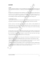
Figure 3: Diagram of the axes [1] .................................................................................................... 8
Figure 4: Indicates where the amplitude is on a waveform............................................................ 9
Figure 5: Indicates where wavelength is measured [4]................................................................. 10
Figure 6: Diagram showing different phase shifts [4] .................................................................. 10
Figure 7: Voltage of peak-to-peak & Voltage of one peak [1] .................................................... 11
Figure 8: Different waves[2] .......................................................................................................... 11
Figure 9: Showing design flow of training package ..................................................................... 21
Figure 10: Showing navigation of training package ..................................................................... 22
Figure 11: First idea for navigation design.................................................................................... 23
Figure 12: Colour scheme & background design1........................................................................ 23
Figure 13: Colour scheme & background design2........................................................................ 24
Figure 14: Fill transform tool in Macromedia Flash MX ............................................................. 24
Figure 15: Adobe Photoshop image of proposed layout............................................................... 25
Figure 16: Proposed layout with images........................................................................................ 25
Figure 17: Final layout design........................................................................................................ 26
Figure 18: First stage of Flash Intro design ................................................................................... 26
Figure 19: Second stage of Flash Intro design .............................................................................. 27
Figure 20: Third stage of Flash Intro ............................................................................................. 27
Figure 21: Final Flash Intro design ................................................................................................ 28
Figure 22: Time line of oscilloscope puzzle animation................................................................ 28
Figure 23: Rollover buttons and home intro information............................................................. 29
Figure 24: Action scripting for the first scope button................................................................... 29
Figure 25: Timeline of scope button movie................................................................................... 31
Figure 26: Navigation bar before & after ...................................................................................... 31
Figure 27: First imp lemented animation for controls ................................................................... 33
Figure 28: Change of timeline........................................................................................................ 34
Figure 29: Display page.................................................................................................................. 35
Figure 30: First and final design of photo background using Adobe Photoshop ........................ 35
Figure 31: Design of button for photo slide .................................................................................. 35
- VI -
i re
CHAPTER 1
1.1 Introduction
Multimedia wasn’t widely used in the past but in the last 10 years, this technology has become apart of
dsh
everyday life. Breaking it down it combines forms of images, text, sound and interactivity to present
information in the senses of visually seeing and hearing from what you would read for example from a
book. Generating ideas and information as visual content to create ease of use and a new way of
learning providing greater knowledge.
fo r
The aim is to use the general aspects described above and create a visually suitable and user-friendly
training package.
ert
1.2 Project scenario & Authors Background
Engineering students (BEng) and Multimedia students (BSc) at the University of Hertfordshire will
sometime during their degree be using an oscilloscope in their laboratory sessions. Often new students
would need help in using such an instrument especially if they are first time users. These technical
fH
instruments are often used in laboratories D405/D411/D421, where lab students conduct investigations
and experiments using this particular machine with other instruments and devices.
At present, the type of information used to present the instructions on how to use the oscilloscope is a
yo
laminated sheet showing the initial setting of various controls, on the reverse there is written
information about the controls and there settings. To first time users of the scope this might be a bit
daunting to them as it is rather cluttered and visually boring. They may not be taking in as much
rsit
information as they should be and might be a little confusing.
There is room for improvement on this particular area, for students to get to grips with handling the do’s
and don’ts of the scope and the gathering of further information for students to understand what they are
Un
ive
dealing with.
1.3 Project Aim & Objectives
1.3.1 Aim
The aim of this project is to create and produce an interactive, audio-visual multimedia-training package
to introduce and aid first time users’ e.g. new students in understanding how to use an oscilloscope. A
computer based training package that will enable
____________________________________________________________________________
Saijal Patel MDB4
1
i re
unsupervised or of minimum supervision, instructing the user in operating the basic functions available
in an oscilloscope. The trainee will be working alongside the PC and will be instructed to perform any
operations before proceeding to the next stage.
dsh
1.3.2 Objectives
The objectives of the project are as follows: -
Developing a successful multimedia package, providing the user with useful learning material, that
fo r
will enable them to learn and remember making the package successful.
Consists of the basic functions available on an oscilloscope e.g. on screen images of the different
ert
parts of the machine
Use of interactivity between the user and package, user able to interact with the package and
fH
respond to the interaction
Development from 2D to 3D images, good use of images and developing a creative and imaginative
package design
Develop an effective and educational training package, providing clear step-by-step and easy to
yo
follow instructions to user. Implementing useful and detailed content but so much so that the
learning experience is not time consuming and user is able to refer back to at their own convenience
Ability to download sections of the package and print out any information as required by user
Adequately demonstrate the fundamental requirements for operating an oscilloscope
Un
ive
rsit
1.4 Methodology
Establishing a methodology is very useful as it helps to prevent faults when developing the system,
therefore resulting in fewer errors.
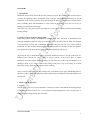
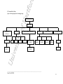
Waterfall also known as the cascade model has been is the chosen methodology for this particular task.
It is the most commonly used method when creating a system from scratch.
____________________________________________________________________________
Saijal Patel MDB4
2
i re
An important feature of the waterfall method is that each stage of the diagram must be completed before
moving on to the next stage. This development life cycle of the system is used to help plan and guide
dsh
development and progression of the project effectively.
Problem
Definition
System Design
fo r
Requirements
Analysis
ert
Implementation
Testing
fH
Integration
System testing
Review, System
Maintenance
Figure 1 Wate rfall Diagram
The following concludes a brief breakdown and understanding of the waterfall diagram and reasons for
yo
its use:
1.4.1 P roblem Definition
Clearly identify the current problem or the task that has been set. This can be done either by
observations, questionnaires, interviews or all three if need be.
rsit
Also taking into account further research into the topic surrounding the problem put forward trying to
gather as much information as possible to create a greater understanding. Without a clear overview or
background knowledge of the problem it would be rather difficult for the developer to achieve the
Un
ive
requirements.
1.4.2 Requirements & Analysis
This stage discusses the user requirements. Certain requirements or specifications that are required for
the system and been put forward by the user and/or client need to be looked at in detail e.g. looking
back at the objectives of the system and any additional requirements obtained by the questionnaires.
____________________________________________________________________________
Saijal Patel MDB4
3
i re
1.4.3 System Design
Designing the system, or in this case a suitable training package, is a major part in development and
creating a successful package. Storyboarding, brainstorming ideas is a necessity in aiding the developer
such as user interface, layout, some form of navigation etc.
dsh
when planning and developing the end package. A break down of the system could be of some help
1.4.4 Implementing & Testing
Working closely with system design stage in the waterfall method. It is a process by which developer
fo r
tests the system during the designing and implementing stage, also a form of trial and error. Once the
system/package is fully implemented the package as a whole is tested, an outside party does this testing
normally. This helps to check for errors and faults that are not always notice or have been missed by the
developer. Also generating some form of feed back of any further improvements that may be add before
ert
final production goes ahead.
fH
1.4.5 Integration & System Testing
This involves working closely with implementation and testing. Making sure all software that is used to
create the package is available to the end user. Using additional software/programs that the client does
not have could arise in problems with costing, unless there has been a budget set that is available to use.
yo
1.4.6 Review & System Maintenance
The final stage of the waterfall is carried out once the system is completed and up and running in the
live environment it has been created for. The reviewing method needs to be devised in order to keep
check of the system and check that it is meeting the requirements that were set at the beginning o f the
project. This also helps to identify the weaknesses or strengths of the system that could lead to possible
rsit
improvements.
1.5 Report Overview
The report provides in depth, detailed documentation of the work carried out to create the visual training
Un
ive
package to introduce an oscilloscope. The various chapters highlight the stages of work going into detail
how the project was carried out and how the developer handled it. Giving insight into the research,
results, design and problems that came about. Reading this report should help people who are not as
familiar with this particular area of technology, understand and follow the work through of this project.
There are 8 chapters to this report:
____________________________________________________________________________
Saijal Patel MDB4
4
i re
1.5.1 Chapter 1, Introduction
This chapter includes project scenario, author’s background, aims and objectives and methodology,
dsh
specific to this project.
1.5.2 Chapter 2, Background Information
This section highlights the background knowledge and information needed to create a successful
training package. It looks into the particular oscilloscopes that are used in the university laboratories
(Tektronix 2225 Oscilloscope (50 MHz)). Looking into much detail about the scope, the controls, its
fo r
settings, what it’s used for and how it works and any other additional information that would be suitable
training purposes. Reasons for obtaining a questionnaire.
ert
1.5.3 Chapter 3, System Analysis/Research
This looks into the results gathered from questionnaires. Questionnaires used to obtain vital information
and findings of what the end user, the students would want out of such a training package. Analysing
the sort of system that is required and if and how it could be obtained by the developer. To help with the
fH
system analysis, research is carried out to obtain the requirements needed. Looking into the type of
software/packages to be used and using one or many of these packages how they could be used to the
developers advantage of creating a successful package.
yo
1.5.4 Chapter 4, Project Plan
The project plan is broken down into sections. Describing an overview of how the project is carried out.
A stage-by-stage development of work. The task and stages are broken down into duration of weeks
using the method of a gaunt chart.
rsit
1.5.5 Chapter 5, System Design Approach
This chapter looks into major detail of the system design, in this case the design, style and layout of the
training package to be. This looks into the creation of the actual package, the steps taken before actually
implementing the design. Storyboarding ideas.
Un
ive
1.5.6 Chapter 6, Implementation
The chapter discusses the actual execution of the package, from taking ideas and design from paper and
actually implementing it on the screen for visual content. This section also encounters problems and
how and if they were solved.
1.5.7 Chapter 7, Testing
When the package is complete testing has to take place. Testing the package as a whole by end users.
This is done to encounter any problems that may have been over looked by the developer.
____________________________________________________________________________
Saijal Patel MDB4
5
i re
1.5.8 Chapter 8, Evaluation/Conclusion/Further Developments
The chapter discusses the original aims and objectives of the project, whether or not the requirements
have been meet successfully. Evaluating the project as a whole, giving an overall conclusion on the
dsh
work carried out. It also looks at project/time management, alternative methods, further developments
Un
ive
rsit
yo
fH
ert
fo r
and problems.
____________________________________________________________________________
Saijal Patel MDB4
6
i re
CHAPTER 2
Background Information
dsh
2.1 Introduction
The final package will intend to be used by the first year engineering and multimedia students at the
University. The package will aim to be used at the student’s induction week of the course. Having this
in mind students who are not familiar with this machine or only have a little knowledge of this
instrument, need to know all of what is available by the machine and the purpose of using such an
fo r
instrument.
“Nature moves in the form of a sine wave, be it an ocean wave, earth-quake, sonic boom, explosion,
sound through air, or the natural frequency of a body in motion”[1]. Using sensors these waves can be
ert
converted into electrical signals that can be observed and studied using an oscilloscope. They are used
so scientists, engineers, technicians and educators are able to see events that change over time use.
rsit
yo
fH
2.2 Oscilloscope Image
This picture is a very close match to the oscilloscopes in the laboratories.
Figure 2: Tektronix 2225 Oscilloscope [3]
Un
ive
2.3 What is an Oscilloscope?
The oscilloscope is a graph-displaying device; it draws the graph of an electrical signal and provides a
way of literarily seeing what is happening in a circuit. The graph shows how signals change over time.
The vertical axis (Y) represents voltage and the horizontal axis (X) represents time.
____________________________________________________________________________
Saijal Patel MDB4
7
i re
dsh
Figure 3: Diagram of the axes [1]
fo r
2.4 Representation of a Signal
A graph of a signal can tell you many things about the signal begin transmitted:
The time and voltage values of a signal
-
Frequency of an oscillating signal
-
‘Moving parts’ of a circuit represented by the signal
-
Frequency with which a particular portion of the signal is occurring relative to other portions
-
Whether or not a malfunctioning component is distorting the signal
-
How much of a signal is direct current (DC) or alternating current (AC)
-
How much of the signal is noise and whether the noise is changing with time
fH
ert
-
2.5 Types of Oscilloscopes
Electronic devices can be classified into 2 categories analog and digital. Analog devices work with
continuously variable signals and digital devices work with discrete binary numbers that represent
yo
voltage samples. For applications either an analog or digital scope would do, however each type has
unique characteristics that can make it more or less suitable for the specific application.
rsit
2.5.1 Analog Oscilloscope - how does it work?
It works by applying the measured signal voltage directly to the vertical axis of an electronic beam that
moves from left to right across the oscilloscope screen, using a cathode-ray-tube. The backside of the
screen is treated with luminous phosphor that glows wherever the electron beam hits it. The signal
Un
ive
voltage deflects the beam up and down proportionally as it moves horizontally across the display,
tracing the waveform on the screen. The more frequently the beam hits the brighter the glow.
2.5.2 Digital Oscilloscope – how does it work?
A digital scope uses an analog-to-digital converter (ADC) to convert the measured voltage into digital
information. It acquires the waveform as a series of samples and stores these samples; it accumulates
enough samples to describe a waveform. T he digital scope then re-assembles the waveform for display
on the screen.
____________________________________________________________________________
Saijal Patel MDB4
8
i re
2.6 Controls
The scope has 33 controls in total. Each control on the oscilloscope operates a different function to one
another. T hese controls are slip into sections as follows: Vertical controls, Horizontal controls and
Trigger controls.
dsh
When starting up the oscilloscope the controls need to be set to a particular setting before work can
proceed. If this is not done then the results you would obtain will probable be of no use, as results
would be inaccurate.
fo r
Refer to appendix C, for the table of controls the names, setting and recommended use.
2.7 Measurements
The two basic measurements you can make are voltage and time measurements. Most if not all
ert
measurements are base on these fundamental techniques. Measurements are taken visually using the
oscilloscope screen.
fH
2.7.1 Amplitude
This is the height of the wave. The amplitude is the maximum positive displacement from the
undisturbed position of the medium to the top of a crest. Divisions on the scope measure this; each
Un
ive
rsit
yo
square on the scope is equal to 1 division.
Figure 4: Indicates whe re the amplitude is on a waveform
2.7.2 F requency
Frequency refers to how many waves made per interval i.e. the number of complete cycles per second in
alternating current direction. The standard unit of frequency is the hertz, abbreviated Hz. If a current
completes one cycle per second, then the frequency is 1 Hz; 60 cycles per second equals 60 Hz.
____________________________________________________________________________
Saijal Patel MDB4
9
i re
2.7.3 Wavelength
Wavelength of a wave is the distance between any two adjacent corresponding locations on the wave
train. This distance is usually measured in one of three ways: crest to next crest, trough to next trough,
ert
fo r
dsh
or from the start of a wave cycle to the next starting point.
Figure 5: Indicates whe re wavelength is measured [4]
180º
270º
360º
rsit
90º
yo
fH
2.7.4 Phase Shift
The phase shift describes how far to the left or right the wave slides.
Figure 6: Diagram showing different phase shifts [4]
Un
ive
2.7.5 Measuring Voltage
Voltage is the amount of electric potential, expressed in volts, between two points in a circuit. Voltage
can be measured from peak-to-peak from the maximum point of a signal to its minimum point. The
oscilloscope is mainly a voltage-measuring device, but other quantities can also be calculated using the
scope. For example, Ohm’s law states that voltage between two points in a circuit equals the current
times the resistance. From any of these quantities you can calculate the third using the following
formula: [1]
Voltage = Current x Resistance
Current = Voltage/Resistance
Resistance = Voltage/Current
____________________________________________________________________________
Saijal Patel MDB4
10
i re
dsh
fo r
Figure 7: Voltage of peak-to-peak & Voltage of one peak [1]
ert
Method of taking voltage measurements is by counting the number of divisions a waveform spans on
the oscilloscope vertical scale.
fH
2.7.6 Time & Frequency Measurements
Using the horizontal scale on the screen of the scope does time measurement. This includes measuring
the period pulse. Frequency is the reciprocal of the period.
yo
2.8 Waves
Wave meaning the generic term for a pattern that repeats over time. Waves are a part of everyday life
from brain waves, ocean waves to electronic waves these are all repetitive patterns moving in
continuous motion. A cycle of a wave is where it repeats itself on the waveform, which is a repetition of
rsit
one cycle. T he most common waveform is the sine wave (sinusoidal wave). Other waveforms include
Un
ive
square wave, saw tooth, the ramp and the triangular wave.
Figure 8: Different waves[2]
____________________________________________________________________________
Saijal Patel MDB4
11
i re
The shape of a waveform reveals a lot of information about its signal. If there is a change in the height
of the wave, this indicates that there has been a changed in voltage. Any time a flat horizontal line
dsh
appears this indicates there has been no change for that length of time.
2.8.1 Sine Wave
Sine wave has harmonious mathematical properties. For example the voltage in wall outlets varies as a
sine wave [2] (sinusoidal waveform). A waveform, which oscillates periodically with the amplitude of
fo r
points on the waveform proportional to the sine of the phase angle of the point [5].
A periodic oscillation. The fundamental waveform from which other waveforms may be generated by
combinations of various group of harmonics. The voltage and current waveforms produced from the
ert
power company generators (alternators) are basic sine waves [6].
2.8.2 Square Wave
Square wave is voltage that turns on and off or goes from high to low at regular intervals [2]. It’s a wave
fH
for testing amplifiers; amplifiers of good quality increase amplitude of the square wave with very little
distortion.
yo
2.8.3 Triangle Wave
A triangle waveform is one with alternating positive- and negative-sloped ramps. Its frequency
spectrum includes all of the odd harmonics. It results from circuits designed to control linear voltages.
rsit
2.9 Further Information Gathering
Gathering further information and creating a backbone for the project further investigation had to take
place. Creating this training package, user involvement is rather important. The purpose of this project
was to create a suitable out come for the end users who are students. A questionnaire was design for this
Un
ive
particular purpose to help identify what the potential users require from such a system. Certain types of
questions were asked to find about the student and how familiar they are with using an oscilloscope, if
they have used one before and how helpful was the handout manual which is given to them.
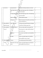
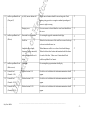
2.9.1 Questions
The questions that were asked were based on the students using the equipment in the induction week at
the university.
-
Have you used an oscilloscope before?
____________________________________________________________________________
Saijal Patel MDB4
12
i re
This was to identify how many students have or have not used an oscilloscope before. This would
indicate how much in depth information content in the package would need to be. The likely hood of
this would be that many were beginners and so basic and in depth but not to over whelming content
dsh
would need to be provided in the training package.
-
How useful are the manuals that are provided in the laboratories?
-
Was the manual straightforward to follow?
This was to indicate how useful the manuals were that are currently provided to them. This would also
-
fo r
help to analysis the current system.
What sort of manual would you prefer to use… printed handout copy, on screen/on line manual, or
ert
both?
This would indicate the sort of help guidance the user would prefer when using the scope.
Have you used an on-line training package before?
-
If yes how useful has it been to your learning?
-
What sort of online training tutorials sites have you used?
fH
-
This would give an idea of how many students have used a training package before and are familiar
yo
with this sort of teaching/learning concept. Also indicating the usefulness of a training package. Finding
out about the sites they have used already would help in researching and creating knowledge of how
these sort of sites are layout and help to encourage the development of this package.
Do you prefer… information text guide, an interactive animated guide or bit of both?
rsit
-
What the user would like to see on the package, how they would like the information to be set out.
-
Would you have found such a training package useful during indication week?
Un
ive
Indicating how useful this package would be to them and encourage a better learning outcome.
____________________________________________________________________________
Saijal Patel MDB4
13
i re
CHAPTER 3
System Analysis/Research
dsh
3.1 Questionnaire results & analysis
A questionnaire was handed out to individual students of a first year engineering class during one of
their lab sessions. They were asked to fill out the questionnaire as though they were in there first week
of induction at university.
fo r
To see the questions and completed questionnaires please refer to appendix A.
3.1.1 Results & Analysis
The results from the questionnaire that were considered the most important are shown below:
ert
Question 1 had been asked to see how many of the students had used an oscilloscope before, the results
show that over half the class had never used an oscilloscope before. T his indicates that most of these
students and likely students in years to come have never used an oscilloscope before therefore having
sort of beginners guide.
fH
little or no knowledge of an oscilloscope a training package would be of great use to these students as a
Question 2 was asked to find out how useful the manuals in labs were. Results show that about 11 out of
yo
25 students found the manual to be of average use giving it a rating of 3 from a scale of 1 to 5, where 1
= no use and 5 = very useful. 6 out 0f 25 students found it quite useful.
Although the students found the manual of average use there is still room for improvement.
rsit
Question 4 results show that 11 out 25 students would like to use both on-screen manual and handouts
and another 11 out of 25 students would still find using handout manuals useful.
The results of question 5 indicate not many students have used an on-line training package before. This
Un
ive
shows that when designing and developing the training package careful consideration needs to be taken
into account in creating a user-friendly package that is very clear and easy to use.
The results to question 8 reveal that the potential end user would like to see a bit of both textual
information as well as interactive animated guide. This shows that users like to
interact while they are working. Seeing visual content and being able to interactive with images makes
the user more interested in what they are doing.
____________________________________________________________________________
Saijal Patel MDB4
14
i re
3.2 Current system analysis
The current form of teaching students how to use the controls on the oscilloscope is done by using a
typed up information sheet. This sheet is presented with an image of the scope and its initial settings for
the controls when it is first used. On the reverse side of this sheet there is written information informing
dsh
the student of the name of the controls, usage of the controls and reasons why they need to be set at
particular settings.
Although this method has been used over the years and has been averagely successful, tutors would like
fo r
to see students getting more involved and gaining a bit more understanding and knowledge about
oscilloscope, their function and purpose of use in labs.
ert
3.2.1 Disadvantages of current method/system
There is a lot of information on one single sheet. It is rather cluttered with written content. Thus
putting the user off reading the information sheet and finding it difficult to follow, missing vital
information or instructions
There is no further information such as waves and calculations, which is considered important
fH
when learning how to use an oscilloscope.
Not slip up in easy to follow sections can be rather confusing when reading
Not very interesting to read
yo
As time moves on so do the traditional ways of working, introducing new and improved methods of
rsit
working and learning, keeping up with technology taking what multimedia has to offer.
3.3 Requirements Analysis
As the end user has already been identified and what the specific need for the system is, system
requirements need to be set as general guidelines for the developer to follow. Following these
requirements closely would help create a successful package having the user in mind and what would be
Un
ive
best suited to them.
3.3.1 System Requirements
Computer based training package
User friendly
Easy to navigate through the package
Break down of the relevant information
Easy to follow instructions
Good use of images
____________________________________________________________________________
Saijal Patel MDB4
15
Interesting content
Clear use of information
Eye catching lay out of package
Use of audio
i re
Use of interactivity
dsh
3.4 Software
To create this training package the main software that was used to build the package was Macromedia
fo r
Flash MX. Microsoft Word was used to create paragraph textual information and Adobe Photoshop was
used to help create images for examples buttons and adjust and improve photographic images.
ert
3.4.1 Macromedia Flash MX
Flash was used as the bases of design for the whole package. Macromedia flash can also be used to
create fully functional websites or can be just used to create animations. The reason for using flash
fH
software to create the package was because it has great features for creating interactive and animated
sites or packages. The presentation of work done in flash is of high quality, allows user to create smooth
graphics while maintaining a low file size, which is important as these files would have a faster
download time. Using flash the user is able to create animated movie clips using a timeline. Method of
yo
using Action Script language which is available to use in flash enables to create user interactivity in the
application. To view flash files the user must have a flash plug-in to view them otherwise it will not be
rsit
seen on their computers.
3.4.2 Adobe Photoshop 7.0.1
This software was used because it allows you to edit images. The software also allows the user to
manipulate photos so that they appear clearer. The software has many features to offer such as, standard
paint and drawing tools so you’re able to draw good graphics. Many layer styles that allow special and
Un
ive
instant effects. Special effect filters to jazz up graphics.
____________________________________________________________________________
Saijal Patel MDB4
16
i re
CHAPTER 4
Project Plan
dsh
4.1 Plan
Gathering background information, research, establishing the requirements for the proposed system and
working with the aim and objectives, a suitable project and development plan needs to be brought into
action.
Managing time is an important factor when starting up a new project. Using time wisely and effectively
fo r
will lead to successful completion of the project. Arranging time and dividing the project tasks into
sections will help to generate a manageable timeline i.e. Gantt chart. If targets and deadlines are not
meet accordingly to the dates set then this would cause set backs, delays and working errors.
ert
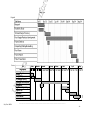
4.2 Tasks/Stages of work
A general plan of work had been set out see below. To see a detailed project plan and dates please refer
fH
to appendix E. Gantt chart (a) shows the initial chart and Gantt chart (b) shows the revised chart.
Research and ideas. This would take a fair amount of time. Gather as much information and
background knowledge. Developing first ideas. Although the bulk of the research would be done at the
start of the project there may be at times in the project where looking back at research and searching
yo
more information will be needed.
Developing ideas content gathering. General ideas for the package layout would be set at this period in
time in the project timeline. This would also included content gathering. The content and information
rsit
that is most likely to be included in the package e.g. images of the scope; break down of the images
using adobe Photoshop, written content that needs to be in the package.
Design and implementation. T his part of the project is the most time consuming and time needs to be
Un
ive
planned accordingly. Good time management equals successful outcome. The steps that were follow:
- Story boarding ideas and design. A record of development of work in progress is kept in a logbook,
which is used to refer during the weeks of development of the training package.
- Implementation of design. This includes on-screen or visual development of work. Creating the pages
for the package, layout, navigation colour scheme etc. Creating animations for the package is very time
consuming and therefore considerable time is needed for this part of the project.
____________________________________________________________________________
Saijal Patel MDB4
17
i re
Testing. Testing is carried out in accordance with implementation as well as a full testing plan at the end
of development of the system. Considerable needs to be taken out for this in order for it to be done
dsh
properly.
Evaluation & conclusion. This part in the project timeline is where the project is evaluated and
concluded. The overall project and development are evaluated and a conclusion is made. This is done
right towards the end where the report is written up this would have been started about 4 weeks before
fo r
deadline.
Poster presentation. This is due a week later after the report is handed in. This includes a poster of the
progress of work carried out over the academic year, which due to be presented in the second week of
Un
ive
rsit
yo
fH
ert
May/2004.
____________________________________________________________________________
Saijal Patel MDB4
18
i re
CHAPTER 5
System Design Approach
This chapter show the design ideas for the proposed system. Using the user requirements and objectives
dsh
that are required for the system, generating a general plan for implementation.
5.1 Basic Content of training package
This shows the basic content of information, how it was initially and the revised content to be included
fo r
in the package:
5.1.1 Initial Content
- Home Page
- What an oscilloscope is
ert
- Controls
- About the controls
- Displays
fH
This was at the beginning of the project. The client had described that the very basics of the
oscilloscope was required from the package not too much information was needed. But over the weeks
of development it had been decided that more information was required from the training package to
yo
make a successful learning package.
5.1.2 Revised Content
Home Page
rsit
General introduction to the training package. Showing the user what the package is about.
What is an oscilloscope
Un
ive
Information about what the oscilloscope is and what it does.
Controls
Information containing the controls, the names of the controls, function of the controls and
recommended use.
Learning the controls
This information for the page indicates on how to use the controls whenever you first start using the
oscilloscope. Explaining the initial settings of the controls and why the they are set in this way.
____________________________________________________________________________
Saijal Patel MDB4
19
Displays
i re
There a 4 main display controls sections; Display controls, vertical controls, horizontal controls and
dsh
trigger controls. T his information will help to describe what they are and mean.
Photographs
This page will hold images of the oscilloscope they see in the laboratories.
Test
fo r
A test incorporated in the training package will help to test the users knowledge and see how much they
have learnt from the package.
Information on waves
ert
This includes information on the oscilloscope output. Information about different waveform and
information about what is displayed on the screen of the scope. Generating background knowledge to
Un
ive
rsit
yo
fH
the user and allowing the user to understanding the meaning and purpose of a scope.
____________________________________________________________________________
Saijal Patel MDB4
20
r
fH
ert
fo
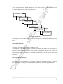
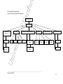
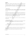
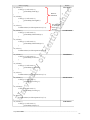
5.2 Content F low Chart
Figure 9: Showing design flow of training package
Flash Introduction
yo
Home Page
Waves
1-10
11-20
Un
ive
Other
Waves
Controls
Learn the controls (flash intro)
rsit
What is an
oscilloscope?
21-30
31-33
Recommended
settings
Displays
Display
Controls
Horizontal
Controls
Summary of
controls
Digital Pictures
Vertical
Controls
Trigger
Controls
Test (flash intro)
Test Part1
Test Part2
____________________________________________________________________________
Saijal Patel MDB4
21
r
fH
ert
fo
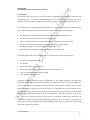
5.3 Navigation Through Package
Figure 10: Showing navigation of training package
Flash Introduction
yo
Home Page
Other
Waves
1-10
11-20
Un
ive
Waves
Controls
Learn the controls (flash intro)
rsit
What is an
oscilloscope?
21-30
31-33
Recommended
settings
Displays
Display
Controls
Horizontal
Controls
Summary of
controls
Digital Pictures
Vertical
Controls
Trigger
Controls
Test (flash intro)
Test Part1
Test Part2
____________________________________________________________________________
Saijal Patel MDB4
22
i re
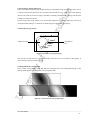
5.4 General P age design and Layout
This section shows the general page design and layout. The package design was based up on the look of
a website to present the package to have a professional look and feel to it. All the pages of the package
will have the same layout reason being to illustrate consistency throughout the package and therefore
dsh
creating no confusion to the user.
Several design ideas using sketches were created and logged into a logbook, improving each step of
development and coming to a conclusion on which design is best suited to the package.
ert
fo r
5.5 First idea for page layout
Navigation
bar
fH
Image of scope
Figure 11: First idea for navigation design
yo
This was the very first idea for a navigation method. This idea was not well suited to the package. It
does not use the space provided very well.
rsit
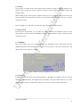
5.6 Backgrounds & Colour scheme
These are the colour schemes ideas that had been designed and a basic background design for the
Un
ive
package. Both figures 12 and 13 were created using Flash MX.
Figure 12: Colour sche me & background design1
____________________________________________________________________________________________
Saijal Patel MDB4
- 23 -
i re
Figure 12 shows a colour scheme that is very basic but at the same time it is very dual. It does not seem
visually appealing they do not bring out much enthusiasm. These colours are not suitable for the
package being designed, its very black and white making the package look and feel black and white in
dsh
other words boring. One of the requirements is to make the user feel interested by what they see
ert
fo r
something that is striking and bold. Figure 13 below shows development of colour design.
fH
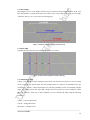
Figure 13: Colour sche me & background design2
The colour combination in figure 13 is more of the look, which is intended for the package. They are
not too bright or overpowering but still have certain professionalism about them. The first two images in
figure 13 bring out a certain character due to the colours used. A particular tool in Flash MX was used
to create the spot light effect. The colours pale yellow and white are also used because they are colours
yo
that stand out well with the colour blue. The colours complement with each other and do not clash as for
rsit
example how yellow would clash with white.
Figure 14: Fill transform tool in Macromedia Flash MX
Un
ive
5.7 Development to final design
There had been several design ideas for the layout of the package and navigation method. It had been
concluded that the main colours that would be used and constant throughout the package would be the
colours which are shown in the first image of figu re 13 above; pale blue, pale yellow and white.
Reasons for using these particular colours, they complement one another very well. The colour blue is
referred to as ‘the working colour’ it has psychological meaning behind it were it’s a colour which
makes
people work and learn making them active and interested, and in this case it is ideal. The colour blue is
widely used in environments such as healthcare (hospitals), in education such as schools and
universities and different work forces such as the police and the royal navy.
____________________________________________________________________________________________
Saijal Patel MDB4
- 24 -
i re
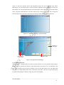
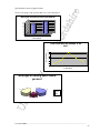
Figure 16 show the proposed layout with integrating images into the background using Adobe
Photoshop to create the image. Figure 15 shows the layout without the image integration. The reason for
choosing this sort of design rather then the one shown in figures 12&13 was to create an abstract design
dsh
effect. Using lines rather than the oval effect suits the topic of the package as the idea of using line
ert
fo r
reflect the object being described. This design also reflects a better position for a navigation bar.
rsit
yo
fH
Figure 15: Adobe Photoshop image of propose d layout
Un
ive
Incorporated
scope images
Buttons on
homepage
Navigation point
Figure 16: Proposed layout with image s
5.7.1 P roblem with layout
Although figure 16, design of pages was quite favoured, it did not seem to be practical for the package.
It did not seem to quite take the likeness of the sketched idea. The images were very difficult to work
with and the images that were being used did not seem to be the ideal images to use. The images that
were used were digital photos taken of the oscilloscope in lab D421. They were of poor quality pixel
resolution. When trying to enlarge the image the picture would distort.
____________________________________________________________________________________________
Saijal Patel MDB4
- 25 -
i re
5.7.2 Solution to layout
After careful consideration and further design development the final layout was created in Flash MX as
shown in figure 17. It was implemented using a number of layers and on each separate layer shape, text
dsh
or buttons were added. The final design is much simpler but at the same time effective. The logo is
constant throughout the package. It is bold and visible on the home page and then it is faded out but is
still visible on rest of the pages. A simple navigation bar is added to the bottom of the page, it is easily
fo r
noticeable and accessible.
Page
Heading
Logo
fH
ert
Page
Content
Navigation
Bar
Figure 17: Fina l layout design
yo
5.8 Flash Intro Design
A flash introduction is what the user first sees when they open up the package. This went through many
design stages too. Figure 18 shows the first stage of design. This was created in Flash MX. T his design
incorporated using a typewriter effect where each letter would appear one after the other as though
rsit
someone was using a typewriter. The background again was created using the fill transform tool in
Flash. With this tool you’re able to manipulate the fill background colour. That is how the indented
Un
ive
white bright looking egg shape was created.
Figure 18: First stage of Flash Intro design
____________________________________________________________________________________________
Saijal Patel MDB4
- 26 -
i re
dsh
Figure 19: Second stage of Flash Intro design
Figure 19 shows the second stage of development for the intro. This particular design used a fading in
fo r
and fading out effect of the words. As one word fades in, then starts to fade out the next word fade in as
the word before it fades out. This was a much smoother running movie and using a darker colour for the
text helps it stands out and is legible.
ert
This seem to be a very basic intro, there wasn’t much going on in this clip, so adding pictures made it
yo
fH
more interesting. Figure 20 shows a development from figure 19.
Fade in fade
out images
Rollover
button
rsit
Button to enter the start
of the training package
Un
ive
Figure 20: Third stage of Flash Intro
Design uses fading in & fading out of oscilloscope images. A button was also added to link the intro to
the homepage of the training package.
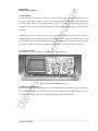
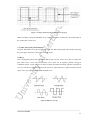
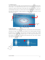
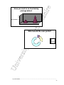
5.8.1 F inal Flash Intro Design
Figure 21 shows the final design for the intro. Instead of using fade in and fade out images I have used a
puzzle form for making up the image. This is more effective. The image was split up into squares using
Adobe Photoshop. Each image was saved separately and imported into Flash MX. A separate movie
was created for this animation, placing the images on to different layers of the timeline to create this
sliding puzzle effect. 14 different layers were used.
____________________________________________________________________________________________
Saijal Patel MDB4
- 27 -
i re
dsh
fo r
ert
yo
fH
Figure 21: Final Flash Intro design
rsit
Figure 22: Time line of oscilloscope puzzle animation
CHAPTER 6
Implementation
Un
ive
6.1 Package implementation
It has been discussed in the previous chapter about the package design. The design and basic
implementation of the general package layout and flash introduction have been explained and discussed
for each particular design. This section concentrates on the training package implementation as a whole.
Work through of discussions of various parts of the package and encountering the problems and solving
of problems.
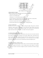
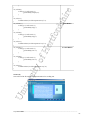
6.2 Home page implementation
The home page was design as a welcome page for the user. This is what they first see once they have
viewed the flash intro. It is an introduction to the package telling the user what the package is about and
what it has to offer.
____________________________________________________________________________________________
Saijal Patel MDB4
- 28 -
i re
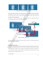
Rollover buttons to the side of the page (scope screen image) were used to view the information on this
page. These buttons were created in Flash, first creating it as a graphic then converting the behaviour to
a button. The colours of the button change once it is rolled over to indicate to the user that the button is
fo r
dsh
active and an action will appear. Refer to figure 23.
On roll out
ert
On rollover
Figure 23: Rollover buttons and home intro information
fH
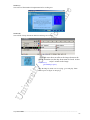
6.2.1 How the animation worked originally
The information that appears when you rollover the scope buttons was in a separate movie. This movie
was then dragged onto the workspace and action scripting on the buttons were added to call the
particular layer/frame action from that movie. Refer to figures 24. The movie must be given an instance
Un
ive
rsit
yo
name otherwise the action on the button would not have worked.
Red flag
indicates
frame name
T he letter ‘a’ indicates
that there is an action
on this frame. The
action here is STOP
Movie
instance
name
Figure 24: Action scripting for the first scope button
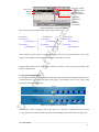
6.2.2 Explanation of the Action Scripting
In the action scripting a Tell Target function is used. This creates an action where by it tells target when
on rollover to look in the movie with the instance name for example here it is rollover and it tells it to
____________________________________________________________________________________________
Saijal Patel MDB4
- 29 -
i re
‘go to and play’ the frame with the name “1text”. On rollout target is told to look in that same movie
with the instance name rollover and tell it to ‘go to and play’ the frame with the name “1back”. Stop
actions are added in the timeline, so once the movie is played then reaches this frame in the timeline the
dsh
movie will stop playing.
6.2.3 P roblems
Problem 1
fo r
Originally the home page is where the main point was where all the other movies would open up in. To
do this a blank movie was added to the timeline layer and given an instance name. Every time a button
on the navigation bar was click on the page would appear in that blank movie on the home page. This
works but because there was information e.g. images and text on the homepage, when clicked on a
the page intended to go to appeared.
Problem 2
ert
button to go to the next page there would be a brief second where the homepage would be seen before
to appear would not appear.
yo
6.2.4 Solving problems
Problem 1
fH
Also when going back to the home page and rolled over the scope buttons the information that is meant
In order to solve this problem changes had to be made. Instead of having the other pages of the package
open up the home page, the actions that were applied to the buttons is as follows: -
rsit
}
on (release) {
loadMovieNum("oscilloscopeMenu3.swf", 0);
}
Each of the pages of the package was saved as separate files. This action means when the button is
Un
ive
released ‘load movie’ and in brackets is the name of the movie in this case ‘oscilloscopeMenu3.swf’
that it will open. All the .swf movies must be saved in the same folder. The movies load up separately
and mot as part of the home page.
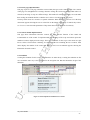
Problem 2
To over come this problem the actions on the buttons that were calling the movie had to be deleted and
the animation had to be changed. The buttons had to be converted to a movie and separate movies of the
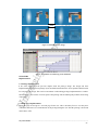
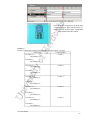
information that appears had to be created. Figure 25 illustrates this.
____________________________________________________________________________________________
Saijal Patel MDB4
- 30 -
This layer contains
the separate movies
that appear when
button is rolled over
i re
Movie layer
Buttons
layer
dsh
This layer
contains the
actions
applied to
the buttons
Figure 25: Timeline of scope button movie
Second button
on (rollOver) {
gotoAndPlay(4);
}
on (rollOut) {
gotoAndPlay(1);
}
on (rollOver) {
gotoAndPlay(5);
}
on (rollOut) {
gotoAndPlay(1);
}
fH
on (rollOver) {
gotoAndPlay(3);
}
on (rollOut) {
gotoAndPlay(1);
}
Third button
ert
First button
fo r
Here is the action script applied to the buttons of the buttons layer.
On the buttons layer the frames are duplicated so when the movies are played from the top layer the
yo
buttons do not disappear. T he formality that has been created here is a movie
playing within another movie. Stop action is added to the frame to stop it from playing further until
another command is set.
rsit
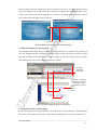
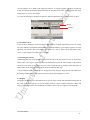
6.3 Navigation Implementation
The navigational structure was implemented on the home page first and then a template of this page was
created and used for the rest of the pages of the package. The templates were used in order to keep
Un
ive
consistency throughout the package.
Before
After
Figure 26: Navigation bar before & after
The animation for the navigation works in the same way as the action scripting described in section
6.2.2 see appendix F section (a) Which shows the action scripting and timeline for the navigation bar.
____________________________________________________________________________________________
Saijal Patel MDB4
- 31 -
i re
Originally the navigation bar button had no text to show what each button represents, only when the
button was rolled over could you tell what the button was. After development text was added so it was
easily recognised as a navigation bar and with out having to rollover the button you would know which
dsh
button was link to which page.
6.3.1 P roblem
When in putting the text on the buttons, they were difficult to hover over. Text would be recognised as a
fo r
selectable icon. In order to click on the button the cursor would have to hover over just the button and
not the text. This would be rather frustrating for the user. T o over come this problem when creating the
text in the properties dialog box for the text the icon ‘selectable’ should not be selected. If this is
ert
selected it indicates the text is selectable on screen. Using this text can also be used to create buttons.
6.4 ‘What is an oscilloscope’ page implementation
This page contents information about what an oscilloscope is. To present this information to the user a
fH
scrolling method of text was to be implemented. Refer to appendix F section (b) which, shows a screen
shot of the first method of implementation for this page. This page also contains a link that goes to a
page with information about waves, explaining the meanings of the functions of a waveform and other
yo
types of waveforms.
6.4.1 P roblem
When creating the scrolling text errors would appear each time it was tested. The reason being was that
the textual information for the page was written in the action scripting and it would not recognised some
rsit
characters such as, explanation marks, comers, speech marks and bullet points. Then arrows were used
as buttons to scroll the text up and down. Due the problem of the text not being recognised these down
Un
ive
did not work.
6.4.2 P roblem Solution
To over come this problem of the text not being read a different method was used to create the
scrollable text box. A new movie animation was created. In this the written information was written in a
text box field. Instead of using buttons for scrolling text up and down, a scroll bar was inputted from the
components tool in Flash MX. T his movie was then dragged on to the existing page on a different layer.
Refer to appendix F section (c) it shows a screen shot of the final method of implementation for this
page.
____________________________________________________________________________________________
Saijal Patel MDB4
- 32 -
i re
6.5 Controls page implementation
This page is part of a sub page, which has a menu within, that goes to the controls profile. The creation
of this page was straightforward. Creating a button to enlarge the oscilloscope image, which when it is
clicked on, the image is swap to a different image. This method for enlarging the image was used rather
dsh
then creating an animated timeline so that the user is able to view the image as they please.
The drop down menu was created as a separate animation. When the image is hovered over the drop
down menu appears allowing the user to select/click on the button of the group of controls they wish to
fo r
see. To see a screen shot and explanation of drop down menu refer to appendix F section (d).
6.5.1 Controls Profile implementation
This page shows information about the controls, the name, and the function of the control and
ert
recommended use of the control. To implement this idea the image of the scope was broken up into the
numbered sections displayed on the image. There are 33 controls for the scope so the menu was split
into 4 sections. The first three containing 10 controls and the last containing the last 3 controls. Each
information about the control.
fH
menu displays the number of the control and when hovered over an animation appears showing the
yo
6.5.2 P roblems
Creating the animation for this section was founded to be rather tricky. Creating the animation at first
was created the same way as the animation for the navigation bar. But this limited the design of the
Un
ive
rsit
animation.
Figure 27: First implemente d animation for controls
____________________________________________________________________________________________
Saijal Patel MDB4
- 33 -
i re
The idea initially was to break up the image shown above, as separate graphics e.g. the bar would fade
in then the background then the image and finally the text, but because this was not possible the whole
image had to be saved as one graphic.
Movies
Buttons
fo r
dsh
To create the animation as designed in logbook a different approach to the animation had to be taken.
ert
Figure 28: Change of timeline
6.5.2 P roblem solved
Figure 30 shows the change of development for this animation. Separate individual movies were created
fH
for each control this enabled the animation that was intended initially e.g. having the sequence of events
appearing one after the other. T he buttons were created as a movie, which call the individual control
movies. Again using movie within a movie method.
yo
6.6 Learning the controls
Summarising this page of the package, a flash intro introduces the page before the user clicks the enter
button where a new page is opened up where the information on how the initial settings of the controls
should be set are show in a diagram form. User is able to skip the intro by clicking on the skip button. A
rsit
button linked to the summary of the controls is also available on this page.
A flash animation of the oscilloscope was incorporated in the design to bring interest and animation to
the package. Making the user interested in what else the package might have to offer.
Un
ive
6.7 Displays
The display menu has a lot of information for the user. In order to make this information manageable to
the reader it has been split in to 4 sections Display controls, vertical controls, horizontal controls and
trigger controls. T he same sort of method movie within a movie was used. Figure 29 illustrates this.
____________________________________________________________________________________________
Saijal Patel MDB4
- 34 -
i re
dsh
Movie
fo r
Movie
Movie
Figure 29: Display page
ert
6.7 Oscilloscope pictures
The pictures were taken using a digital camera. Different angles of the scope were taken and the best 6
were chosen to place in the package. T he background of the picture slide was designed and created in
Adobe Photoshop. The buttons were also created in Adobe Photoshop. To create these two images the
rectangle tool was used to create the basic shape required. Then using layer prosperities was able to
fH
manipulate and change the look of the shape creating a 3D look to the image to give it depth and make
rsit
yo
it look realistic.
Un
ive
Figure 30: First and fina l de sign of photo background using Adobe Photoshop
Figure 31: Design of button for photo slide
____________________________________________________________________________________________
Saijal Patel MDB4
- 35 -
i re
6.8 The Test
The test was created to test the knowledge of the students once they have run through the package. To
create this test 8 questions are asked and the student has a choice of two answers a or b. If they get the
question right there is a scoreboard at the top of the page that indicates to the user whether they have got
dsh
the question right or whether they have got it wrong. Scores of plus 10 for a right answer and minus 10
for a wrong answer indicate to the user whether the question they answered is right or wrong. Here’s an
example of the action script that is added to the buttons a and b of the first question on the second part
fo r
of the test.
Button (a)
on (release) {
_root.total = _root.total - 10;
ert
}
Button (b)
fH
on (release) {
_root.total = _root.total + 10;
}
A variable name is given to the text box that shows the score. The variable is named ‘total’ so the action
Un
ive
rsit
yo
above tells it to display the answer in that text box.
____________________________________________________________________________________________
Saijal Patel MDB4
- 36 -
i re
CHAPTER 7
Testing
When the package is completed a method of testing has to take place. This is done to insure that
functionality of the package is running well and encounter any problems that may have been over
dsh
looked during the implementation of the package. It is an essential part of the project process providing
the developer with answer on how well the package is working in the environment it has been designed
for.
fo r
7.1 Method of testing
The most common procedure of testing is called Black Box testing. This involves testing the package
once it is fully completed insuring the requirements are met. It focuses on the testing of functional
ert
requirements.
During the package development testing also took place while the package was being implemented. The
problems that were encountered during the production of the package as specified in the previous
fH
chapter indicate the evidence of testing during implementation. Testing needed to be carried out during
implementing the package to insure functions and scripting were working well along side each other.
It’s a procedure of trail and error that takes place during the implementation.
running smoothly.
yo
Students and fellow colleagues tested the package, in order to see whether or not the package was
7.2 Viewing results table
To refer to the table of test that took place look at appendix D. This give the full testing that went ahead
rsit
after the package was full implemented. Below are some notes that refer to the testing table:
Test No.3
The answer to this test is yes and no. Yes because all the sub title animations do work but on the
Un
ive
test page of the package the sub title reads ‘What is an oscilloscope’ when is should read ‘test’.
Test No.11
There is fault to the clicking of the scope buttons. This is if you were to click the button twice in one
action the animation of the drop menu will open, then when click the same button to close the drop
menu the next drop menu would open without you having clicked the next scope button.
____________________________________________________________________________________________
Saijal Patel MDB4
- 37 -
i re
7.3 Feedback
Some of the main pointers that had to be considered while testing the package
The interaction the user has with the package
-
Could the package be said to be user friendly
-
Over all layout & design
-
The quality of information that has been provided in the package
-
Quality of navigation and links
dsh
-
fo r
Due to the overall testing of the package as a whole a conclusion can be made that 90% of the package
is running well. T he idea of creating a test in the package was founded very interesting. All the above
Un
ive
rsit
yo
fH
ert
points were commented on well although there is room for improvement.
____________________________________________________________________________________________
Saijal Patel MDB4
- 38 -
i re
CHAPTER 8
Evaluation/Conclusion/Further Developments
dsh
8.1 Evaluation
The main aim of the project was to create an interactive, multimedia-training package to introduce and
aid first time users’ i.e. students in understanding how to use an oscilloscope. Instructing the user in
operating the basic functions available in an oscilloscope unsupervised or with minimu m supervision.
fo r
The overall objective of the required package and the user requirements were followed carefully during
the development of the package. T he following were achieved successfully from the project
Providing the user/student with useful learning material useful and detailed content
Provides user with the basic functions of the oscilloscope
The use of some interactivity were by the introduction of providing a test was included
Good use of images and developing a creative and imaginative package design
Providing clear step-by-step and easy to follow instructions to user
Demonstrate the fundamental requirements for operating an oscilloscope
fH
ert
yo
The following shows the user requirements that were obtained successfully from the project:
Computer based training package
User friendly
Easy to navigate through the package
Easy to follow instructions & Break down of the relevant information
Clear use of information & Interesting content
Eye catching lay out of package
rsit
Un
ive
In order to obtain the objectives and user requirements for the package provided to be rather time
consuming. Some of the achievements that could not be obtained were use of audio and the ability for
user to down load work and print information that they would require. Although audio was not
implemented in the package and one of the objectives was to implement this, due to the timing of time
management a lot more time was spent on the interactivity of the package, package look and layout and
the good use of information material. Looking at it further this is where the main bloke of the project
lays so in order to follow this much time was spent to successfully complete these objectives and
requirements. It had come to the conclusion that using audio may not be of much use as the package is
mainly based on visual communication. Not discarding the audio factor it could still be regarded and
looked into as further development.
_______________________________________________________________________________________
Saijal Patel MDB4
- 39 -
i re
Using Macromedia Flash MX to build the package has provided to be time consuming. Producing the
individual movies using the time line was where was the most. Although flash has been used in the past
they were very basic implementation, learning how to use and incorporate action scripting into the
dsh
animation was a major part of the project, which also was relatively time consuming.
8.2 Time Management
The reason for time management is to keep to a time scheduling plan in order to keep to date and
complete the project in the given time. Creating a Gantt chart to follow during the development of the
fo r
project was a good way to keep a schedule of project management. A Gantt chart helps to manage tasks
by breaking major tasks into more manageable smaller task and setting deadline of completion for the
task. Keeping to such a plan leads to a successful end result.
Time keeping was founded to be difficult in completing this project due the vast amount of time spent
ert
on implementing. Appendix E indicates the original Gantt chart that was created at the start of the
project estimating the time of completion for each of the tasks according to how big the task was. It also
shows the revised Gantt chart indicating the adjustments of time for certain tasks e.g. implementation
fH
and testing.
8.3 Conclusion
The general report outlines the way the task that was given has been handle. Detailing the procedures
been through to implement the project giving the reader a feed back of events over the months and bring
yo
the project to a conclusion.
The package was created using the multimedia software application Macromedia Flash MX. Although
this package has been rather time consuming to use it has brought good results to the overall completed
rsit
package. It has benefited the package with the input and creativity of the developer with interactive and
animated feature and giving the presentation of work a high quality of viewing. The project as a whole
has been a good working experience and has been carried out successfully although future
Un
ive
developments can be made.
8.4 Further developments
Further developments can be made to improve the package functionality. For example some of the
developments are listed below:
-
Introducing audio to aid the user
-
The ability to down load
-
Incorporating and a lab exercise for the students to follow through
-
Incorporating actual lab movies, of students showing how to use the oscilloscope
All the above could be included in a further improvement of the package with investigating the use of
other software to develop it on.
_______________________________________________________________________________________
Saijal Patel MDB4
- 40 -
i re
Reference
[1] http://www.tek.com/Measurement/cgi-bin/framed.pl?
http://www.tek.com/Measurement/cgi
dsh
Tektronix website
[2] http://www.tek.com/Measurement/App_Notes/XYZs/signal_integrity.pdf
[3] http://physics.ucsd.edu/students/cou rses/summer2002/ss2/physics2cl/phys2CLmanual.pdf
Waves websites
[5] www.cpccorp.com/pqglossary.htm
fo r
[4] Section IVhttp://id.mind.net/~zona/mstm/physics/waves/partsOfAWave/waveParts.htm
http://id.mind.net/~zona/mstm/physics/waves/partsOfAWave/waveParts.htm
Un
ive
rsit
yo
fH
ert
[6] www.liebert.com/support/glossary/power_gloss.asp
_______________________________________________________________________________________
Saijal Patel MDB4
- 41 -
Bibliography
i re
http://www.tek.com/Measurement/cgi
http://www.tek.com/Measurement/cgibin/framed.pl?Document=/Measurement/App_Notes/XYZs/index.html&FrameSet=oscilloscopes
http://www.phys.washington.edu/~jeff/courses/433A/lab-writeups/scope.html
http://www.phys.washington.edu/~jeff/courses/433A/lab
http://www.doctronics.co.uk/scope.htm#VOLT S_DIV
dsh
http://www.engga.uwo.ca/people/hladak/ECE%20240A/LAB%202
http://www.engga.uwo.ca/people/hladak/ECE%20240A/LAB%202%20OSCILLOSCOPE%20AUG%202003-%20LM-1.pdf
fo r
http://www.tek.com/Measurement/scopes/selection/pdf/55W_13768_1_ease.pdf
http://www.phy.olemiss.edu/~thomas/weblab/222%20Lab%20Manual/Exp.25_Oscope-sum2002.pdf
http://www.phy.olemiss.edu/~thomas/weblab/222%20Lab%20Manual/Exp.25_Oscope
http://www.bkprecision.com/download/scope/ScopeSafety.pdf
www.bkprecision.com/download/scope/ScopeSafety.pdf
ert
http://www.singaren.net.sg/library/presentations/14Mar03/presentation_16.pdf
http://www.tektronix.com
fH
http://physics.ucsd.edu/students/courses/summer2002/ss2/physics2cl/phys2CLmanual.pdf
http://vlab.ee.nus.edu.sg/vlab/vr-osci/index.html
http://vlab
http://www.smaphysics.ca/phys30s/waves30s/basics.html
yo
http://id.mind.net/~zona/mstm/physics/waves/introduction/introductionWaves.html
http://id.mind.net/~zona/mstm/physics/waves/partsOfAWave/waveParts.htm
http://www.tiepie.nl/
http://w
rsit
http://www2.sfu.ca/sonic-studio/handbook/Sine_Wave.html
http://www2.sfu.ca/sonic
http://physics.usask.ca/~hirose/ep225/animation/wave-general/anim-sine.htm
http://physics.usask.ca/~hirose/ep225/animation/wave
http://www2.sfu.ca/sonic-studio/handbook/Triangle_Wave.html
http://www2.sfu.ca/sonic
Un
ive
howstuffworks.com
http://www.creationstudio.co.uk/flash/index.htm
http://www.creationstudio.co
http://www.synergydesign.co.uk/pages/training_director01.htm
http://www.cdsm.co.uk/learning/e_learning.htm
http://www.macromedia.com/software/fireworks/productinfo/reviews_news/
http://www.maxhelp.com/
http://www.macromedia.com/software/flash/?promoid=home_prod_flash_082403
http://www.macromedia.com/sof
www.kirupa.com
_______________________________________________________________________________________
Saijal Patel MDB4
- 42 -
Appendix Content
i re
A. Questionnaire
B. Questionnaire results
dsh
C. Table of controls
D. Testing table
E. Gantt Chart Before & After
fo r
F. Action scripting, timelines & screen shots
a) Action scripting and timeline for the navigation bar.
b) Screen shot of the first method of implementation for scrolling text
d) Screen shot of drop down menu
Un
ive
rsit
yo
fH
e) Action scripting for control buttons
ert
c) Screen shot of final method of implementation for scrolling text
_______________________________________________________________________________________
Saijal Patel MDB4
- 43 -
i re
dsh
fo r
ert
fH
Un
ive
rsit
yo
Appendix A
_______________________________________________________________________________________
Saijal Patel MDB4
- 44 -
QUESTIONNAIRE
i re
(From Saijal Patel, final year BSc project Student)
Please pretend that this is Induction Week and you are in our labs for the very first time
Yes
No
dsh
1. Have you used an oscilloscope before?
1 2
3
4
5
fo r
2. How useful are the manuals in the labs, for using an oscilloscope? From a scale of 1-5 (1=
no use…5 = very useful)
3. When using the manual for the first time, was it straightforward to follow?
No
Sort of
ert
Yes
fH
4. When using the oscilloscope for the first time would you prefer using a user manual, which
is…
Handout print copy manual
On screen/on-line manual
Yes
No
yo
5. Have you used an on-line training package before?
Both
6. If yes how useful had it been to your learning, from a scale of 1-5 (1= no use…5 = very
useful)
2
3
4
5
rsit
1
7. What sort of on-line tutorial sites have you used?
____________________________________________________________________________
__________________________________________________________________
Un
ive
8. Do you prefer?
Information text guide
An interactive animated guide
Bit of both
9. Would you have found such a training package useful during your induction week program?
Yes
No
Thank you for taking the time to fill out this questionnaire. It has been very much appreciated
_______________________________________________________________________________________
Saijal Patel MDB4
- 45 -
i re
dsh
fo r
ert
fH
Un
ive
rsit
yo
Appendix B
_______________________________________________________________________________________
Saijal Patel MDB4
- 46 -
i re
Questionnaire results in graph format
These are the graph of the questions that were of most importance.
dsh
Have you used an oscilloscope before?
Yes
fo r
14
12
10
8
6
4
2
0
No
No.of students
ert
How useful was the manuals in the
labs?
10
fH
No.of students
12
8
6
4
2
yo
0
1
2
3
4
5
Scale from 1-5
Un
ive
rsit
What type of training bases would
you use?
11
11
Handout
Online
Both
3
_______________________________________________________________________________________
Saijal Patel MDB4
- 47 -
i re
dsh
Have you used an on-line training
package before?
20
15
5
0
No
ert
Yes
fo r
No.of students 10
1 1
5
N/A
Text
Animated
Bit of both
18
Un
ive
rsit
yo
fH
What would the user prefer?
_______________________________________________________________________________________
Saijal Patel MDB4
- 48 -
i re
dsh
fo r
ert
fH
Un
ive
rsit
yo
Appendix C
_______________________________________________________________________________________
Saijal Patel MDB4
- 49 -
r
INTENSITY
BEAM FIND
FOCUS
TRACE
ROTATION
POWER
Power Indicator
POSITION
TRACE SEP
10
11
12
CH 1- BOTH CH 2
NORMINVERT
ADD-ALTCHOP
Recommended Use
Adjusts trace brightness.
Compresses display to within CRT limits.
Adjusts for finest trace thickness.
Adjusts trace parallel to centerline.
Compensate for ambient lighting, trace speed, trigger frequency.
Locate off-screen phenomena.
Optimize display definition.
Compensate for earth's field.
Turns power on and off.
Illuminates when power is turned on.
Moves trace up or down screen.
Moves the magnified trace vertically with respect to the
unmagnified trace when HORIZONTAL MODE is set to
ALT.
Selects signal inputs for display.
Control power to the instrument.
Know power condition.
Position trace vertically and compensate for dc component of signal.
Position unmagnified and horizontally magnified traces for
convenient viewing and measurement.
Inverts the Channel 2 signal display.
ADD shows algebraic sum of CH 1 and CH 2 signals.
ALT displays each channel alternately. CHOP switches
between CH 1 and CH 2 signals during the sweep at 500
kHz rate.
Selects vertical sensitivity.
Provides continuously
The CAL control can be
variable deflection factors
pulled out to vertically
between calibrated
magnify the trace by a factor
positions of the
of 10. Limits bandwidth to 5
VOLTS/DIV switch.
MHz.
Reduces gain by at least
25:1.
In AC, isolates dc component of signal. In GND, gives
Un
ive
5
6
7, 9
8
fH
ert
fo
1
2
3
4
Function
yo
Title
rsit
No.
13
14
VOLTS/DIV
Variable (CAL)
15
AC-GND-DC
View either channel independently or both channels simultaneously
Provide for differential (CH 1 - CH 2) or summed (CH 1 + CH 2)
signals when ADD is selected.
Display summed or individual signals.
Adjust vertical signal to suitable size.
Match signals for common
Inspecting small signals.
mode readings. Adjust
height of pulse for
rise-time calculations.
Selects method of coupling input signals to the vertical deflection
_______________________________________________________________________________________
Saijal Patel MDB4
- 50 -
r
SEC/DIV
Variable (CAL)
22
MAG(X5 - X10
- X50)
18
23
25
26
27
29
30
31
PROBE
ADJUST
FINE is convenient for moving magnified traces when
either ALT or MAG is selected.
X1 displays only normal (horizontally unmagnified)
waveform. ALT displays normal and magnified waveforms
alternately. MAG displays only the magnified waveform.
Selects time-base speed.
Provides continuously variable uncalibrated sweep speeds
to at least 2.5 times the calibrated setting.
Selects degree of horizontal magnification.
Provides safety earth and direct connection to signal
source.
Provides approximately 0.5-V,1-kHz square wave.
Un
ive
24
fH
ert
fo
20
21
17
yo
19
CH 1 OR X CH
2 OR Y
POSITION
COARSE
POSITION
FINE
X1 -ALT- MAG
rsit
16
reference point and allows recharging of input coupling
capacitor. In DC, couples all components of signal.
Provides for input signal connections. CH 1 gives
horizontal deflection when SEC/DIV is in X-Y.
COARSE is convenient for moving unmagnified traces
SLOPE
Selects the slope of the signal that triggers the sweep.
LEVEL
TRIG'D
Selects trigger-signal amplitude point.
Indicator lights when sweep is triggered in P-P AUTO,
NORM, or TV FIELD.
Arms trigger circuit for SGL SWP.
Varies sweep holdoff time 10:1.
CH 1, CH 2, and EXT trigger signals are selected directly.
In VERT MODE, trigger source is determined by the
RESET
HOLDOFF
SOURCE
system.
Apply signals to the vertical deflection system.
Control trace positioning in horizontal direction.
Control trace positioning in horizontal direction.
Select normal, comparative or expanded waveforms.
Set horizontal speed most suited to requirements.
Extend the slowest speed to at least 1.25 s/div
Examine small phenomena in detail.
Chassis ground connection.
Match probe capacitance to individual circuit. This source may be
used to check the basic functioning of vertical and horizontal circuits
but is not intended to check their accuracy.
Provide ability to trigger from positive-going or negative-going
signals.
Select actual point of trigger.
Indicate trigger state.
Improve ability to trigger from aperiodic signals.
Select source of signal that is coupled to the trigger circuit.
_______________________________________________________________________________________
Saijal Patel MDB4
- 51 -
r
EXT INPUT
fH
ert
fo
33
yo
COUPLING
Select how the triggering signal is coupled to the trigger circuit.
Trigger from a source
other than vertical signal.
Also used for single-shot
application.
Provide reference blips by intensity
modulation from independent source.
Un
ive
rsit
32
VERTICAL MODE switches as follows: CH 1: trigger
comes from Channel 1 signal. CH 2: tr igger comes from
Channel 2 signal. BOTH-ADD and BOTH CHOP: trigger
is algebraic sum of Channel 1 and Channel 2 signals.
BOTH-ALT: trigger comes from Channel 1 and Channel 2
on alternate sweeps.
AC blocks dc components and attenuates signals below 15
Hz. LF REJ blocks dc components and attenuates signals
below about 30 kHz. HF REJ blocks dc components and
attenuates signals above about 30 kHz. DC couples all
signal components.
Connection for applying
Connection for applying
external signal that can
external signal that can be used
be used as a trigger.
for intensity modulation.
_______________________________________________________________________________________
Saijal Patel MDB4
- 52 -
i re
dsh
fo r
ert
fH
Un
ive
rsit
yo
Appendix D
_______________________________________________________________________________________
Saijal Patel MDB4
- 53 -
r
File name
Testing Action
No.
On click should go to the page that is requested
ALL Animations
On viewing a requested page sub title animation should play
2
Navigation Links ALL
3
Sub titles
yo
animation
Once clicked on file flash intro animation should play
(Flash Intro Page)
Enter Button (TEKTRONIX)
Once clicked on button, should go to home page of package
Rollover scope buttons
On rollover animation should play
Scroll Bar
When click on the arrows of the scroll bar or move the bar up
oscilloscopeMenu3.swf
Page)
7
Un
ive
(What is an oscilloscope
Flash Scope animation on right
oscilloscopeMenu4.swf
below
Flash Intro
oscilloscopeMenu2.swf
No
See Notes
Intro.exe
(Home Page)
6
Yes
ALL Navigation Links
ALL
5
Does it work
ALL Navigation Rollover
4
Expected result
On rollover of navigation buttons animation should play
Navigation Animations
rsit
1
fH
ert
fo
Test
or down text should move too
Once entered the page animation should work in a continues
loop
Rollover button (find out more
The button ‘find out more about waves’ on rollover image
on waves) & Button link
should change & on click go to the page requested
Scope image animation
When entered into this page scope animation should be
played
_______________________________________________________________________________________
Saijal Patel MDB4
- 54 -
r
fH
ert
fo
(Controls Page)
8
oscilloscopeMenu5.swf
On rollover image should change colour and the enlarge
image’ Rollover & action
action should work once clicked on
Drop down menu
On rollover drop down menu should appear
Drop down menu links
On click the button requested should go to the requested page
Intro flash animation for page
On entering the page flash intro animation for page should
(Learning the controls)
play
On rollover button image should change and on click should
load oscilloscopeMenu5b.swf movie (next part to the page)
Flash animation
On entering the page flash animation for page should play
(Learning the controls)
Skip button
On click should skip the flash animation
On click should load oscilloscopeMenu5c.swf movie (next
rsit
oscilloscopeMenu5b.swf
next part to the page
‘Here’ button
before
oscilloscopeMenu5c.swf
Scroll Bar
Un
ive
10
yo
‘Click to begin’ button
9
Button ‘Click to enlarge
(Learning the controls)
part to the page)
When click on the arrows of the scroll bar or move the bar up
or down text should move too
next page to previous
page
11
oscilloscopeMenu6.swf
Rollover scope buttons &
Scope images should change colour once rolled over. On
(Displays)
Button links
click buttons should animation a drop menu showing other
headings & buttons
_______________________________________________________________________________________
Saijal Patel MDB4
- 55 -
r
fH
ert
fo
See notes below
Drop menu button links
These buttons should display information once clicked on
Display Button rollover and
Button should change image on rollover. Link should go to
link
next bit of information
Next display button and link
Button should change image on rollover. Link should display
scope screen animation
oscilloscopeMenu7.swf
(Test part 1)
Scrolling bars
When click on the arrows of the scroll bar or move the bar up
rsit
oscilloscopeMenu8.swf
Button 1-6 on the panel
(Digital pictures page)
13
Animation should run as planned
yo
12
Display screen animation
(a) & (b) answer buttons all
Un
ive
Keeping score
Next button
14
or down text should move too
On clicking on these buttons different pictures should appear
for each button. (Six different images in total)
All the answer buttons should be in working order. Each
button giving a positive or negative number depending on if
answer is right or wrong
Once an answer is selected then the score board should show
the score
On rollover colour should change. On click should load
oscilloscopeMenu8b.swf movie (test part 2)
oscilloscopeMenu8a.swf
Flash intro
Once entering this page test flash intro should play
(Test intro)
Rollover button ‘click to begin’
On rollover colour should change and on click should load
and link
oscilloscopeMenu8.swf movie (test part 1)
_______________________________________________________________________________________
Saijal Patel MDB4
- 56 -
r
oscilloscopeMenu8b.swf
fH
ert
fo
15
(a) & (b) answer buttons all
(Test part 2)
All the answer buttons should be in working order. Each
button giving a positive or negative number depending on if
answer is right or wrong
Keeping score
Once an answer is selected then the score board should show
the score
oscilloscopeMenu9.swf
Sinusoidal wave animation
On entering the page the animation should play
(Waves)
Scroll bar
When click on the arrows of the scroll bar or move the bar up
yo
16
oscilloscopeMenu10.swf
18
When buttons are rolled over colour of test should change.
frequency, phase, sinusoidal,
When clicked on these buttons information should be shown
Controls1.swf
for each of the titles. ‘Other waves’ button should load
links
oscilloscopeMenu10.swf movie.
Animation
On entering this page animation should play
On rollover of each button the information animation should
Rollover button 1-10
(Controls 1-10)
19
Controls2.swf
Rollover button 11-20
(Controls 11-20)
20
Controls3.swf
(Controls 21-30)
other waveforms rollover &
Un
ive
(Other waves)
Amplitude, wavelength,
rsit
17
or down text should move too
Rollover button 21-30
appear
On rollover of each button the information animation should
appear
On rollover of each button the information animation should
appear
_______________________________________________________________________________________
Saijal Patel MDB4
- 57 -
r
Controls4.swf
fH
ert
fo
21
Rollover button 31-33
appear
Un
ive
rsit
yo
(Controls 31-33)
On rollover of each button the information animation should
_______________________________________________________________________________________
Saijal Patel MDB4
- 58 -
i re
dsh
fo r
ert
fH
Un
ive
rsit
yo
Appendix E
_______________________________________________________________________________________
Saijal Patel MDB4
- 59 -
r
fH
ert
fo
Gantt Chart
Task
Week Commencing
Un
ive
Revised
rsit
yo
Original
October
N
Novem
ovember
ber
December
January
February
March
6 13 20 27 3 10 17 24 1 8 15 22 29 5 12 19 26 2 9 16 23 1 8 15 22
29
April
5 12 19 26
May
3 10
Research
FeasabilityStudy
1st ideas/Design&planning
Final Design/Practical development
ProjectSeminar
Completetion/testing/evaluating
Final DemoPrep
ProjectReport
PosterPresentation
_______________________________________________________________________________________
Saijal Patel MDB4
- 60 -
i re
dsh
fo r
ert
fH
Un
ive
rsit
yo
Appendix F
_______________________________________________________________________________________
Saijal Patel MDB4
- 61 -
fo r
dsh
i re
Section (a)
Action scripting and timeline for the navigation bar
Un
ive
rsit
yo
fH
ert
Section (a) continued on next page
_______________________________________________________________________________________
Saijal Patel MDB4
- 62 -
dsh
Rollover
animation
i re
Button
First button
fo r
On click action
on button to
load .swf
movie
Second Button
Third Button
Fourth Button
Un
ive
rsit
yo
fH
ert
Action scripting
on (rollOver) {
tellTarget ("/rolloverNav") {
gotoAndPlay("homePg");
}
}
on (rollOut) {
tellTarget ("/rolloverNav") {
gotoAndPlay("hmePgBck");
}
}
on (release) {
loadMovieNum("oscilloscopeMenu2.swf", 0);
}
on (rollOver) {
tellTarget ("/rolloverNav") {
gotoAndPlay("WhatIsAScope");
}
}
on (rollOut) {
tellTarget ("/rolloverNav") {
gotoAndPlay("WhatIsAScope2");
}
}
on (release) {
loadMovieNum("oscilloscopeMenu3.swf", 0);
}
on (rollOver) {
tellTarget ("/rolloverNav") {
gotoAndPlay("Controls");
}
}
on (rollOut) {
tellTarget ("/rolloverNav") {
gotoAndPlay("Controls2");
}
}
on (release) {
loadMovieNum("oscilloscopeMenu4.swf", 0);
}
on (rollOver) {
tellTarget ("/rolloverNav") {
gotoAndPlay("learning1");
}
}
on (rollOut) {
tellTarget ("/rolloverNav") {
gotoAndPlay("learning2");
}
}
on (release) {
loadMovieNum("oscilloscopeMenu5.swf", 0);
}
on (rollOver) {
tellTarget ("/rolloverNav") {
gotoAndPlay("display1");
Fifth Button
_______________________________________________________________________________________
Saijal Patel MDB4
- 63 -
i re
dsh
fo r
Sixth Button
Seventh Button
rsit
yo
fH
ert
}
}
on (rollOut) {
tellTarget ("/rolloverNav") {
gotoAndPlay("display2");
}
}
on (release) {
loadMovieNum("oscilloscopeMenu6.swf", 0);
}
on (rollOver) {
tellTarget ("/rolloverNav") {
gotoAndPlay("dig1");
}
}
on (rollOut) {
tellTarget ("/rolloverNav") {
gotoAndPlay("dig2");
}
}
on (release) {
loadMovieNum("oscilloscopeMenu7.swf", 0);
}
on (rollOver) {
tellTarget ("/rolloverNav") {
gotoAndPlay("test1");
}
}
on (rollOut) {
tellTarget ("/rolloverNav") {
gotoAndPlay("test2");
}
}
on (release) {
loadMovieNum("oscilloscopeMenu8a.swf", 0);
}
Un
ive
Section (b)
Screen shot of the first method of implementation for scrolling text
_______________________________________________________________________________________
Saijal Patel MDB4
- 64 -
fo r
dsh
i re
Section (c)
Screen shot of final method of implementation for scrolling text
fH
ert
Section (d)
Screen shots of drop down menu timeline and image on screen
yo
When the cursor does not rollover the image shown on the
left, the animation sets the drop down menu as closed. Action
script is written to the image:
Un
ive
rsit
on (rollOver) {
gotoAndStop("open");
}
Once the image is rolled over it is saying ‘ go to and play’ frame
named open. See figure on next page.
_______________________________________________________________________________________
Saijal Patel MDB4
- 65 -
i re
dsh
fH
ert
fo r
Once the image is rolled over the drop down
menu will appear. The rectangle boxes are
buttons that link to other pages, which holds
information about the controls.
Un
ive
rsit
yo
Section (e)
Example of the action scripting used for the buttons on the controls 1-10 page
Action script
Control Number
on (rollOver) {
Control 1
gotoAndPlay(3);
}
on (rollOut) {
gotoAndPlay(1);
}
on (rollOver) {
Control 2
gotoAndPlay(4);
}
on (rollOut) {
gotoAndPlay(1);
}
on (rollOver) {
Control 3
gotoAndPlay(5);
}
on (rollOut) {
gotoAndPlay(1);
}
on (rollOver) {
Control 4
gotoAndPlay(6);
}
on (rollOut) {
gotoAndPlay(1);
}
on (rollOver) {
Control 5
gotoAndPlay(7);
}
on (rollOut) {
gotoAndPlay(1);
_______________________________________________________________________________________
Saijal Patel MDB4
- 66 -
dsh
i re
Control 6
Control 7
ert
fo r
Control 8
Control 9
Control 10
Un
ive
rsit
yo
fH
}
on (rollOver) {
gotoAndPlay(8);
}
on (rollOut) {
gotoAndPlay(1);
}
on (rollOver) {
gotoAndPlay(9);
}
on (rollOut) {
gotoAndPlay(1);
}
on (rollOver) {
gotoAndPlay(10);
}
on (rollOut) {
gotoAndPlay(1);
}
on (rollOver) {
gotoAndPlay(9);
}
on (rollOut) {
gotoAndPlay(1);
}
on (rollOver) {
gotoAndPlay(11);
}
on (rollOut) {
gotoAndPlay(1);
}
_______________________________________________________________________________________
Saijal Patel MDB4
- 67 -