1
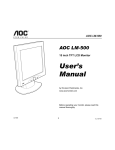
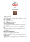
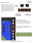
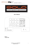
EUROPEAN ORGANISATION
FOR THE SAFETY OF AIR NAVIGATION
EUROCONTROL
EUROCONTROL EXPERIMENTAL CENTRE
Test Communication Management Unit
EEC Note No. 23/96
EEC Task C07
EATCHIP Task FCO.ET3.ST08
Issued: September 1996
The information contained in this document is the property of the EUROCONTROL Agency and no part should be
reproduced in any form without the Agency’s permission.
The views expressed herein do not necessarily reflect the official views or policy of the Agency.
REPORT DOCUMENTATION PAGE
Reference:
EEC Note No. 23/96
Security Classification:
Unclassified
Originator:
EEC - COM
(Communication)
Originator (Corporate Author) Name/Location:
EUROCONTROL Experimental Centre
B.P.15
F - 91222 Brétigny-sur-Orge CEDEX
FRANCE
Telephone : +33 1 69 88 75 00
Sponsor:
EATCHIP Development Directorate
Sponsor (Contract Authority) Name/Location:
EUROCONTROL Agency
Rue de la Fusée, 96
B -1130 BRUXELLES
Telephone : +32 2 729 9011
TITLE:
Test Communication Management Unit
Authors
Date
Pages
Figures
Photos
Appendix
References
09/96
iv+16
4
2
1
4
Hans P. ENGLMEIER
João M. M. MARTINS
EATCHIP Task
Specification
FCO.ET3.ST08
EEC Task No.
Task. No Sponsor
Period
C07
EAS2
4/96 to 5/96
Distribution Statement:
(a) Controlled by:
Head of COM
(b) Special Limitations: None
(c) Copy to NTIS:
YES / NO
Descriptors (keywords):
AT58 - Mode-S Subnetwork - Aircraft Equipment Simulation - ARINC Protocols -Test Communication
Management Unit - HP UX Environment - Remote Installation - Advanced ARINC Card - HP UX C
Abstract:
This report describes the software architectural design and user manual of the Test Communication
Management Unit.
This document has been collated by mechanical means. Should there be missing pages, please report
to:
EUROCONTROL Experimental Centre
Publications Office
B.P. 15
91222 - BRETIGNY-SUR-ORGE CEDEX
France
EEC Note No. 23/96
EEC Task No. C07
EATCHIP Task No. FCO.ET3.ST08
Issued : September 1996
Test Communication Management Unit
by
Hans Peter ENGLMEIER
and
João Manuel MATEUS MARTINS
EUROCONTROL Experimental Centre
Summary
This report describes the software architectural design and user manual of the
Test Communication Management Unit
Test Communication Management
iii
CONTENTS
1. ACRONYMS AND ABBREVIATIONS DEFINITIONS ..........................................................................1
2. PURPOSE AND SCOPE ............................................................................................................................2
3. MAJOR FEATURES OF THE TEST COMMUNICATION MANAGEMENT UNIT ..........................2
4. GENERAL OVERVIEW ...........................................................................................................................3
5. MESSAGES FORMAT ..............................................................................................................................4
5.1. INTRODUCTION ...........................................................................................................................................4
5.2. MSP MESSAGE FORMAT .............................................................................................................................4
5.3. BROADCAST MESSAGE FORMAT ..................................................................................................................4
5.4. GICB MESSAGE FORMAT............................................................................................................................4
6. TCMU SOFTWARE ARCHITECTURAL DESIGN ................................................................................5
7. TEST COMMUNICATION MANAGEMENT UNIT USER MANUAL .................................................7
7.1. INTRODUCTION ...........................................................................................................................................7
7.2. INSTALLING THE TEST COMMUNICATION MANAGEMENT UNIT ......................................................................7
7.3. RUNNING THE TEST COMMUNICATION MANAGEMENT UNIT..........................................................................8
7.4. TEST COMMUNICATION MANAGEMENT UNIT OPERATING INSTRUCTIONS ......................................................9
7.4.1. GICB Editor .......................................................................................................................................9
7.4.2. Main User Interface..........................................................................................................................13
7.4.2.1. Broadcast Messages.......................................................................................................................13
7.4.2.2. MSP Messages ...............................................................................................................................13
7.4.2.2.1. Load Message or File..................................................................................................................13
7.4.2.2.2. Load File ...................................................................................................................................13
7.4.2.2.3. Load Message .............................................................................................................................13
7.4.2.2.4. Receive File ................................................................................................................................14
7.4.2.2.5. Quit TCMU.................................................................................................................................14
7.4.3. Final Considerations ........................................................................................................................14
8. TEST PROCEDURES AND FUTURE DEVELOPMENTS ...................................................................15
9. REFERENCES .........................................................................................................................................16
APPENDIX 1
PHOTO N° 1
PHOTO N° 2
Test Communication Management
iv
1.
Acronyms and Abbreviations Definitions
AAC
Advanced ARINC Card
ADLP
Aircraft Data Link Processor Unit
ADS
Automatic Dependent Surveillance
ATN
Aeronautical Telecommunication Network
BDS
Binary Data Store. Register number with 56 bit in the Mode S
transponder.
ELM
Extended Length Message
GICB
Ground Initiated Comm-B Messages
GPFT
General Purpose File Transfer Protocol
ICAO
International Civil Aviation Organisation
LDU
Link Data Unit
MA
Comm-A message, 56 bit field
MC
Comm-C message, 80 bit field
MOPS
Minimal Operation Requirements Document
MSP
Mode S Specific Protocol
SLM
Short Length Message
STNA
Service Technique de la Navigation Aérienne
TRT
Télécommunications Radio-électriques et Téléphoniques
TUB
Technische Universität Braunschweig
XPDR
Mode S Transponder
Test Communication Management
1
2.
Purpose and Scope
The purpose of this document is to provide an overall description of the software
architectural design and user manual of the Test Communication Management Unit
developed at the EUROCONTROL Experimental Centre.
3.
Major Features of the Test Communication Management Unit
Test Communication
Managment Unit
TCMU
GICB
EDITING
MESSAGES
EDITING
GICB
GENERATION
DOWNLINK
MESSAGES
GENERATION
DATA LINK
MONITORING
ARINC 429-14
GENERAL PURPOSE
FILE TRANSFER
GENERATION
Figure no. 1 - Major features of the Test Communication Management Unit
Test Communication Management
2
The Test Communication Management Unit is a software device Installed in a HPUX workstation and using an Advanced ARINC Card version 2 (EEC Note No.
17/94).
This software enables the user to generate or monitor Mode S data link messages.
The transmission of MSP, Broadcast and GICB messages, is supported by the AAC
using an ARINC 429-14 GPFT Protocol.
4.
General Overview
ARINC 429-14
caring MSP,
Broadcast and GICB’s
Messages
Mode S
Transponder
ARINC 718
Protocol
TCMU
Simulation
Mode S
Specific
Services
Entity
Aircraft Data
Link Processor
ARINC 429-14
caring X25 packets
ISO 8208
Entity
Figure no. 2 - General overview of an airborne ADLP environment
The figure shown above gives a general overview of the airborne Aircraft Data Link
Processor environment.
With the evolution of the new generation of Mode S equipment and having in mind
the implementation of the future ATN, the need to have low cost tools able to
evaluate the harmonisation of communication protocols between different types of
AVIONICS equipment set, became apparent.
The software feature presented in this note, the TCMU, is able to simulate a Mode S
Specific Services entity as shown above in an experimental and test environment.
Installed in HP-UX workstation connected to a standard network environment, this
software offers the possibility of being remote controlled and accessed from
anywhere.
Using the ARINC 429-14 GPFT which corresponds to the ISO level 2 link layer, this
software is open to the encapsulation of any communication protocol running over it.
An immediate application of these principles and behaviours is the transport of
MSP, Broadcast and GICB messages.
Test Communication Management
3
The format of these messages is defined in the next chapter.
5.
5.1.
Messages Format
Introduction
The format defined below correspond to the one used by the Rockwell & Collins
ADLP.
5.2.
MSP Message Format
The format of the MSP message transmitted between the ADLP and the TCMU for
uplink and downlink shall be as follows:
5.3.
Byte 1
⇒ MSP Message Type, always 13 (hexadecimal).
“
2
⇒ MSP Channel Number, defined in the ADLP MOPS document, table 2-6.
“
3
⇒ MSP Length, number of MSP data bytes that follows.
“
4..n ⇒ MSP Data.
Broadcast Message Format
The format for a Broadcast message transmitted between the ADLP and the TCMU
shall be as follows:
Byte 1
5.4.
⇒ Broadcast Message Type, always 11 (hexadecimal).
⇒ Broadcast Identifier, defined in the ADLP MOPS document, table 2-7.
“
2
“
3..8 ⇒ Broadcast Data.
GICB Message Format
The format for a GICB message transmitted to the ADLP shall be as follows:
Byte 1
⇒ GICB Message Type, always 10 (hexadecimal).
⇒ GICB Register Number, defined in the ADLP MOPS document, table 2-5.
“
2
“
3..9 ⇒ GICB Data.
An example of a GICB message for the register 40 can be found in appendix No. 1.
Test Communication Management
4
6.
TCMU Software Architectural Design
1- Uplink
Monitor
3- Downlink
Monitor
2- User
Interface
F1
F3
7- GICB
Editor
F2
4- Uplink
Driver
5- Main
Process
F5
F6
F4
6- Downlink
Driver
F7
8- GICB
Generator
F8
9- AAC
Interface
F9
High Level
TCMU part
N0
Test Communication
Management Unit
installed in a HP-UX
workstation
10- AAC
Driver
N1
11- AAC
Firmware
Advanced
Arinc Card
version 2
board
A0
A1
ARINC 718 Bus
Figure no. 3 - TCMU software architectural design
Test Communication Management
5
Notes :
1.
2.
3.
F1 to F9 are System V IPC facilities, shared memory and semaphores
N0 and N1 are HP-UX kernel data transfer blocks
A0 and A1 are ARINC channels
As shown in figure No. 2, the TCMU is basically a data link processor. This software
device can be split in three parts, the high level running in the HP-UX workstation,
the HP-UX driver to access the AAC and finally, the low level software running in
the card, the firmware.
The high level part performs the following tasks: AAC driver interface, user
interfacing, MSP, GICBs and Broadcast messages generation and finally data link
monitoring. This part was written in HP-UX C programming language.
Since the application is running in a HP-UX operating system it became necessary
to implement a HP-UX driver to access the card.
This driver developed by Hewlett-Packard France can be configured accordingly
with the chosen AAC interrupt level or memory address.
The configuration manual of this driver is not included in this document but can be
supplied by EUROCONTROL.
Finally, the low level software running in the card, the firmware, implementing the
high speed ARINC Williamsbourg 429-14 Bit Oriented Protocol.
The firmware architectural design and functional description are not included in this
document but can be supplied by EUROCONTROL.
Test Communication Management
6
7.
Test Communication Management Unit User Manual
7.1.
Introduction
The purpose of this chapter is to give a general overview of how a user can install
and implement this software package and, at the same time, to describe how to use
all the TCMU software facilities.
7.2.
Installing the Test Communication Management Unit
The TCMU software is archived in the file “tcmu.tar”. In the subdirectory TCMU use
the command “tar -xvf tcmu.tar” to extract all related files. In the subdirectory TCMU
/tcmu.bin execute the file “make0” to compile the source files which are located in
the subdirectory TCMU/tcmu.src. After successful compiling the following
executable files should be found.
“tcmumain"
Main process
*“tcmuaac"
AAC interface
*“tcmup"
Uplink driver.
“tcmudown"
Downlink driver
*“tcmudownmon"
Downlink monitor
*“tcmupmon"
Uplink monitor
“tcmuser"
User interface.
“tcmu"
File script to start running the TCMU
*“tcmugigen"
GICB generation file
“tcmugiedit"
GICB editor
“gicb.dat”
Default file with AVIONICS data
“sem.ftok.tcmu”
IPC semaphores facilities reference file
“shm.ftok.tcmu”
IPC shared memory facilities reference file .
“gpftcmu.exe"
AAC firmware
* Note : All screen output messages are recorded in a file with extension “.rec”.
Test Communication Management
7
The complete list of files necessary to run the TCMU should also include the HP-UX
driver necessary to establish the connection between the AAC firmware and this
software application.
7.3.
Running the Test Communication Management Unit
To start running the user should type "tcmu". This script file before activating the 9
processes mentioned below asks the name of the GICB file used.
If nothing is written, after having pressed <ENTER> key, the file “gicb.dat” is read by
default, see Photo1. Each of the 9 processes activated are running in a single
« hpterm » visual window, see Photo 2.
TCMU_DOWNLINK_DRIVER
⇒
“tcmudown”
TCMU_UPLINK_DRIVER
⇒
“tcmup”
TCMU_DOWNLINK_MONITOR
⇒
“tcmudownmon”
TCMU_UPLINK_MONITOR
⇒
“tcmupmon”
TCMU_AAC_INTERFACE
⇒
“tcmuaac”
TCMU_USER_INTERFACE
⇒
“tcmuser”
TCMU_MAIN_PROCESS
⇒
“tcmumain”
TCMU_GICB_GENERATOR
⇒
“tcmugigen”
TCMU_GICB_EDITOR
⇒
“tcmugiedit”
Use the mouse to select the correspondent « hpterm » window. How to operate with
all processes will be described in the next chapter.
Test Communication Management
8
7.4.
Test Communication Management Unit Operating Instructions
7.4.1. GICB Editor
The GICB editor is an on line editor of simulated AVIONICS data. Data can be
introduced having as parameters the BDS number, the resolution and the
minimum and maximum value accepted.
BDS
5
DATA
RANGE
RESOLUTION
Airborne Format
Surveillance Status
Turn Indicator Bit
Barometric Altitude
0, 7..14
0..3
0..1
50,175 ft
------------------------------25 ft
0..1
+ 90°
+ 180°
-----------0.0007 °
0.0014 °
0, 5,6
0..128
+ 180°
50,175 ft
--------------------2.816 °
25 ft
0..1
+ 90°
+ 180°
-----------0.0007 °
0.0014 °
+ 180°
4g
+ 180°
131,072 ft
0.18°
0.001 g
0.044°
8 ft
4.096 Mach
1,024 Kt
+ 180°
+ 180°
0.001 Mach
0.5 Kt
0.044°
0.044°
Time Bit
Latitude
Longitude
6
Type
Movement MOV_SPM
Track
Barometric Altitude
Time Bit
Latitude
Longitude
40
Flight Path Angle
Flight Path Acceleration
Corrected Angle of Attack
Barometric Correction Altitude
50
Mach Number
Computed Air Speed
Track Angle True
Track Angle Magnetic
Test Communication Management
9
BDS
DATA
RANGE
RESOLUTION
+ 180°
2,048 Kt
+ 16,384 ft/min
+ 512°
0.044°
0.5 Kt
64 ft/min
0.5°
65,536 ft
+ 180°
270
271
16 ft
0.8°
Binary Input
Binary Input
60
Track Angle Magnetic
Ground Speed
Altitude Rate
Static Air Temperature
70
Selected Altitude Range
Selected Heading
Status Word 1
Status Word 2
80
Selected Airspeed
Selected Altitude Rate
Selected Altitude
Status Word 1
512 Kt
16,384 ft/min
45,536 ft
Label 270
0.25 Kt
16 ft/min
16 ft
Binary Input
90
Selected Mach Number
Selected Altitude Rate
Selected Altitude
Status Word 2
4.096 Mach
16,834 ft/min
65,536 ft
Label 271
0.002 Mach
16 ft/min
16 ft
Binary Input
AO
Cross Track Error
Vertical Deviation
Acceleration
128 nm
2,048 ft
+1g
0.004 nm
1 ft
0.016 g
BO
Computer Airspeed
True Airspeed
Mach
Heading (magnetic)
1,024 Kt
2,048 Kt
4.096 Mach
+ 180°
0.25 Kt
0.5 Kt
0.00025 Mach
0,18°
21
Magnetic Heading
True Air Speed
Static Air Temperature
Normal Acceleration
+ 180°
2,048 Kt
+ 512°C
+1g
0.18°
0.5 Kt
0.5° C
0.016 g
31
Bearing to Waypoint
Time to Go
Distance to go
+ 180°
399.9 min
399.9 nm
0.18°
0.1 min
0.1 nm
Test Communication Management
10
BDS
DATA
RANGE
RESOLUTION
3 characters
3 characters
+ 180°
ISO 5
ISO 5
0.18°
0.00035°
0.0007°
8 ft
41
Active Waypoint 1
Active Waypoint 2
Desired Track
51
Latitude
Longitude
Altitude
+ 90°
+ 180°
131,072 ft
61
G.M.T.
Flight Number
HHMMSS
xxxx
71
Roll Angle
Altitude Rate
Wind Speed
Wind Angle
+ 90°
+ 8,192 ft/min
256 Kt
+ 180°
0,35°
128 ft/min
1 Kt
0.703°
CO
Radio Height
Average Static Pressure
Altitude
8,192 ft
1,024 mb
131,072 ft
1 ft
0.25 mb
1 ft
24
Centre of Gravity
Gross Weight
99.9 %
131,072 lbs
0.1 %
160 lbs
Test Communication Management
11
BDS
DATA
RANGE
RESOLUTION
17
N1 Actual Engine # 1
Fuel Flow Engine # 1
Total Air Temperature
Static Air Temperature
256 % rpm
32,768 lb/hr
± 512°C
± 512°C
0.13 % rpm
8 lb/hr
0.5°C
0.5°C
27
N1 Actual Engine # 2
Fuel Flow Engine # 2
Total Air Temperature
Static Air Temperature
256 % rpm
32,768 lb/hr
± 512°C
± 512°C
0.13 % rpm
8 lb/hr
0.5°C
0.5°C
37
N1 Actual Engine # 3
Fuel Flow Engine # 3
Total Air Temperature
Static Air Temperature
256 % rpm
32,768 lb/hr
± 512°C
± 512°C
0.13 % rpm
8 lb/hr
0.5°C
0.5°C
47
N1 Actual Engine # 4
Fuel Flow Engine # 4
Total Air Temperature
Static Air Temperature
256 % rpm
32,768 lb/hr
± 512°C
± 512°C
0.13 % rpm
8 lb/hr
0.5°C
0.5°C
1A
Aircraft Identification
Aircraft Identification
Aircraft Identification
2 char. ISO5
2 char. ISO5
2 char. ISO5
Label 233
Label 234
Label 235
1B
Aircraft Identification
Aircraft identification
2 char. ISO5
2 char. ISO5
Label 236
Label 237
Test Communication Management
12
7.4.2. Main User Interface
This process allows the user to terminate a TCMU session and to edit or send
downlink MSP or Broadcast messages.
7.4.2.1. Broadcast Messages
To chose this option type <0>. Confirm it by typing <y>, <Y> or <ENTER>.
Type <Y>, <y> or <ENTER> to confirm your edition and <N> or <n> to cancel it.
For the complete editing of your Broadcast message fill the following displayed
table. Use decimal characters and type <ENTER> to finish.
.
BROADCAST MESSAGE
BROADCAST IDENTIFIER
7.4.2.2. MSP Messages
7.4.2.2.1. Load Message or File
To chose this option type <1>. Confirm it by typing <y>, <Y> or <ENTER>.
7.4.2.2.2. Load File
To chose this option type <1>. Confirm it by typing <y>, <Y> or <ENTER>.
Type your file name and type <ENTER> to finish. Confirm it by typing <y>, <Y> or
<ENTER>. If your file does not exist the following message will be printed in the
screen:
“ Your file does not exist. ”
To complete your edition of fill the following displayed table. Use decimal numbers
and type <ENTER> to finish.
MSP PACKET
MSP CHANNEL NUMBER
Type <Y>, <y> or <ENTER> to confirm your edition and <N> or <n> to cancel it.
7.4.2.2.3. Load Message
To chose this option type <2>. Confirm it by typing <y>, <Y> or <ENTER>.
Test Communication Management
13
Type your message with a maximum of 644 characters and type <ENTER> to finish.
644 Characters corresponds to a single LDU.
Type <Y>, <y> or <ENTER> to confirm your edition and <N> or <n> to cancel it.
For the complete editing of your MSP message fill the following displayed table. Use
decimal numbers and type <ENTER> to finish.
MSP PACKET
MSP CHANNEL NUMBER
Type <Y>, <y> or <ENTER> to confirm your edition and <N> or <n> to cancel it.
7.4.2.2.4. Receive File
To chose this option type <2>. Confirm it by typing <y>, <Y> or <ENTER>.
Type your file name and type <ENTER> to finish. Confirm it by typing <y>, <Y> or
<ENTER>.
If your file already exist the following message will be printed in the screen:
“ Your file already exist, do you want to overwrite”
If you want to overwrite type <y>, <Y> or <ENTER>, otherwise type <n> or <N>.
To stop recording type <ENTER>.
7.4.2.2.5. Quit TCMU
To quit and close all processes type <q> or <Q>. Confirm it by typing <y>, <Y> or
<ENTER>. To cancel it type <N> or <n> .
7.4.3. Final Considerations
All the other processes do not require any user operation.
Test Communication Management
14
8.
Test Procedures and Future Developments
Rockwell & Collins
Aircraft Mode S Equipment Set
GPS
Antenna
GPS RF
Datalink
Mode S
Antenna
GPS
CONTROL
BOX
Mode S RF
Datalink
TCMU
XPDR
ADLP
ARINC
429-14 GPFT
Test Bench
IFR or
Thompson & TRT
Uplink
Mode S RF
Interrogations
Figure no. 4 TCMU Simulation environment
With the purpose of doing an evaluation of the Rockwell & Collins Mode S aircraft
equipment set, several tests were made using the simulation environment shown
above. This equipment set is composed of a Mode S transponder (XPDR), a Global
Positioning System (GPS), an Aircraft Data Link Processor (ADLP) and a control
box. The major interests of these tests were to establish a data link able to transport
GICB, MSP and broadcast messages for uplink and downlink using ARINC 429-14
GPFT between the TCMU and this equipment set.
Test Communication Management
15
9.
References
EEC Note No. 17/94 - ADVANCED PC ARINC CARD - VERSION 2
by H.P. ENGLMEIER
ARINC Document - MARK 3 Air Traffic Control Transponder (ATCRBS / Mode S)
ARINC Characteristic 718-4, 15.12.1989
ICAO Aeronautical Telecommunications (Annex 10)
Test Communication Management
16
Appendix 1
1. GICB Message for the register number 40.
Bit 1
Status bit of flight path angle, label 322, range + - 180°, 10 bit,
resolution 0,18° .
Bit 2
Bit 3..12
Sign bit
Data = 190°
Bit N° 1
12
1 1 1 1 1 0 1 1 0 0 0 0
Bit 13
Status bit of flight path acceleration, label 323, range 4 g, 12 bit,
resolution 0.001g
Bit 14
Bit 15..26
Sign bit , always 0
Data = 0,016 g
Bit N° 13
26
1 0 0 0 0 0 0 0 0 1 0 0 0 0
Bit 27
Status bit of corrected angle of attack, label 241, range + - 180°, 12
bit, resolution 0,044°
Bit 28
Bit 29..40
Sign bit
Data = 10°
Bit N° 27
40
1 0 0 0 0 0 1 1 1 0 0 1 0 0
Bit 41
Status bit of barometric corrected altitude, label 204, range 131072 ft,
14 bit, resolution 8 ft
Bit 42
Bit 43..56
Sign bit, always 0
Data = 34000 ft
Bit N° 41
56
1 0 0 1 0 0 0 0 1 0 0 1 1 0 1 0
Test Communication Management
1
The GICB message will be :
10 GICB message type
40 Register number
c3 GICB data = c3980420e4909a
98
04
20
e4
90
9a
All numbers are in hexadecimal notation.
Test Communication Management
2