1
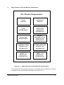
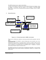
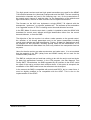
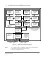
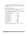
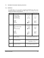
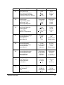
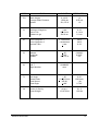
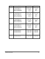
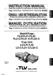
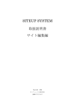
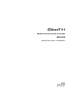
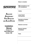
EUROPEAN ORGANISATION
FOR THE SAFETY OF AIR NAVIGATION
EUROCONTROL
EUROCONTROL EXPERIMENTAL CENTRE
SITE MONITOR DEMONSTRATOR
EEC Note No. 28/96
EEC Task C07
EATCHIP Task SUR.3
Issued: December 1996
The information contained in this document is the property of the EUROCONTROL Agency and no part should be
reproduced in any form without the Agency’s permission.
The views expressed herein do not necessarily reflect the official views or policy of the Agency.
REPORT DOCUMENTATION PAGE
Reference:
EEC Note No. 28/96
Security Classification:
Unclassified
Originator:
EEC - COM
(Communication)
Originator (Corporate Author) Name/Location:
EUROCONTROL Experimental Centre
B.P.15
F - 91222 Brétigny-sur-Orge CEDEX
FRANCE
Telephone : +33 1 69 88 75 00
Sponsor:
EATCHIP Development Directorate
Sponsor (Contract Authority) Name/Location:
EUROCONTROL Agency
Rue de la Fusée, 96
B -1130 BRUXELLES
Telephone : +32 2 729 9011
TITLE:
SITE MONITOR DEMONSTRATOR
Authors
Date
Pages
Figures
Photos
Appendix
References
12/96
iv+18
4
2
0
6
Hans P. ENGLMEIER
João M. M. MARTINS
EATCHIP Task
Specification
SUR.3
EEC Task No.
C07
Task. No Sponsor
Period
4/96 to 11/96
Distribution Statement:
(a) Controlled by:
Head of COM
(b) Special Limitations: None
(c) Copy to NTIS:
YES / NO
Descriptors (keywords):
Mode-S Subnetwork - Aircraft Equipment Simulation - ARINC Protocols - Site Monitor Demonstrator HP-UX Environment - Remote Access - Advanced ARINC Card - HP UX C
Abstract:
This report describes the software architectural design and user manual of the Site Monitor Demonstrator.
This document has been collated by mechanical means. Should there be missing pages, please report to:
EUROCONTROL Experimental Centre
Publications Office
B.P. 15
91222 - BRETIGNY-SUR-ORGE CEDEX
France
EEC Note No. 28/96
EEC Task No. C07
EATCHIP Task No. SUR.3
Issued : December 1996
Site Monitor Demonstrator
by
Hans Peter ENGLMEIER
and
João Manuel MATEUS MARTINS
EUROCONTROL Experimental Centre
Summary
This report describes the software architectural design and user manual of the
Site Monitor Demonstrator
Site Monitor Demonstrator
iii
CONTENTS
1. ACRONYMS AND ABBREVIATIONS DEFINITIONS.......................................................................... 1
2. PURPOSE AND SCOPE............................................................................................................................ 2
3. INTRODUCTION...................................................................................................................................... 2
4. MAJOR FEATURES OF THE SITE MONITOR DEMONSTRATOR .................................................. 3
5. GENERAL OVERVIEW........................................................................................................................... 4
6. SITE MONITOR DEMONSTRATOR SOFTWARE ARCHITECTURAL DESIGN ............................ 6
7. SITE MONITOR DEMONSTRATOR USER MANUAL ........................................................................ 8
7.1. INTRODUCTION .......................................................................................................................................... 8
7.2. INSTALLING THE SITE MONITOR DEMONSTRATOR ....................................................................................... 8
7.3. RUNNING THE SITE MONITOR DEMONSTRATOR........................................................................................... 9
7.4. SITE MONITOR DEMONTRATOR OPERATING INSTRUCTIONS........................................................................ 10
7.4.1. GICB Editor .................................................................................................................................... 10
7.4.2. Main User Interface......................................................................................................................... 14
7.4.2.1. Flight Data ................................................................................................................................... 14
7.4.2.1.1. Low Security Level ..................................................................................................................... 14
7.4.2.1.2. High Security Level.................................................................................................................... 14
7.4.2.1.3. Change Password..................................................................................................................... 15
7.4.2.2. Downlink Messages....................................................................................................................... 15
7.4.2.2.1. On Line Messages ..................................................................................................................... 15
7.4.2.2.2. Pre-defined Messages ............................................................................................................... 15
7.4.2.3. Quit Site Monitor Demontrator ................................................................................................ ..... 17
7.4.3. Final Considerations........................................................................................................................ 17
8. REFERENCES......................................................................................................................................... 18
PHOTO N° 1 .................................................................................................................................................. 1
PHOTO N° 2 .................................................................................................................................................. 2
Site Monitor Demonstrator
iv
1.
Acronyms and Abbreviations Definitions
AAC
Advanced ARINC Card
ACAS
Aircraft Collision Avoidance System
ADLP
Aircraft Data Link Processor Unit
ATN
Aeronautical Telecommunication Network
BDS
Binary Data Store. Register number with 56 bit in the Mode S
transponder.
CTS
Clear to send
DLPU
Data Link Processor Unit
ELM
Extended Length Message
GDLP
Ground Data Link Processor
GICB
Ground Initiated Comm-B Messages
IIMSES
Initial Implementation Mode-S in Enhanced Surveillance
RTS
Request to send
SLM
Short Length Message
SMD
Site Monitor Demonstrator
SNTF
Sub-Network Test Facility
TUB
Technische Universität Braunschweig
XPDR
Mode S Transponder
Site Monitor Demonstrator
1
2.
Purpose and Scope
The purpose of this document is to provide an overall description of the software
architectural design and user manual of the Site Monitor Demonstrator test tool
developed at the EUROCONTROL Experimental Centre.
3.
Introduction
The Site Monitor Demonstrator is part of the IIMSES programme and is a test tool
for the radar stations involved in this programme. This will be an industrial product,
the EEC produces it only as a demonstrator.
Site Monitor Demonstrator
2
4.
Major Features of the Site Monitor Demonstrator
Site Monitor Demonstrator
GICB
EDITING
MESSAGES
EDITING
GICB
GENERATION
DOWNLINK
MESSAGES
GENERATION
DATA LINK
MONITORING
FLIGHT
IDENTIFICATION
EDITING and
GENERATION
CONTROL WORD
EDITING and
GENERATION
FLIGHT ALTITUDE
EDITING and
GENERATION
ARINC 718
PROTOCOL
GENERATION
ARINC 429
PROTOCOL
GENERATION
Figure no. 1 - Major features of the Site Monitor Demonstrator
The Site Monitor Demonstrator test tool is a software device Installed in a HP-UX
workstation and using an Advanced ARINC Card version 2 /1/.
Site Monitor Demonstrator
3
The SMD software has two major functionalities.
The first, is the capacity of generate and monitor Mode-S data link messages, using
an ARINC 718 protocol, and the second, is the capacity of generate flight
identification, control word and flight altitude broadcast messages using an ARINC
429 protocol.
5.
General Overview
Mode S Antenna
Mode S Radar
ARINC 718 caring
Mode S Messages
RADAR
XPDR
S W IT C H B O X
D E L A Y L IN E S
REMOTE
CONTROL
P C A R IN C
CARD
S IT E
M O N IT O R
DLPU
ARINC 429 caring
Flight Identification
Control Word
Flight Altitude
Network Protocol
Figure no. 2 - General overview of a SMD environment
There are two differences between normal grounded aircraft equipment and the
SMD :
The first, is a delay line installed in a parrot transponder near the radar to put it at a
longer distance /2/.
The second, is the existence of a special device, a DLPU or a ADLP, which can also
execute the functions of the transponder control box and the altimeter. This device
can be realised by a workstation with a PC ARINC card /1/. Installed in a network
environment it can be used in a remote mode.
The ARINC card has two receivers and 4 multiplexed transmitters. It uses a Harris
ARINC processor which allows different transmission speeds for reception and
transmission.
Site Monitor Demonstrator
4
Two high speed receivers and two high speed transmitters are used for the ARINC
718 interface between the (American) transponder and the SMD. The two remaining
transmission channels are used in the following way: one, for the transmission of
the control word, channel 3, and the other, for the transmission of the altitude and
flight identification, channel 4. Both channels use low speed transmission.
The firmware on the AAC can implement a single ARINC 718 channel with the
transponder, “xpdrx.exe”, or a double “xpdrdax.exe”. The software of the workstation
is an upgraded version of TDLP including control box and altimeter functions.
In the EEC Mode S avionics test chain, a switch is installed to take the ARINC 429
broadcast for control word, altitude and flight identification either from the control
box and altimeter, or from the SMD.
The objective of the site monitor is to allow a radar operator or the ground control,
the variation of all aircraft parameters sent to the parrot transponder including
control word, altitude and flight identification. Further, all data link applications must
be available for test purposes, including special cases as the transmission of 10
COMM-B between two radar beam hits, and verify whether the transponder has lost
any data.
Users for the site monitor are radar constructors and radar users. It is not excluded
that the material of the EEC (delay lines and ARINC cards) will be used for the
industrial SMD production.
The SMD is a simple test tool and has nothing to do with the end to end test chain
for data link applications foreseen in the ATN program, the Sub Network Test
Facility SNTF. Nevertheless, the SMD upgraded by an interface to the GDLP could
be a part of the end to end test chain mention above. If this option is accepted, the
workstation of the SMD could house the software to be developed.
In the moment the SMD is compatible with actual used DLPU, but in a near future, it
must be slightly modified to be compatible with the ADLP. This is due to the
implementation of the GDLP.
Site Monitor Demonstrator
5
6.
Site Monitor Demonstrator Software Architectural Design
1- Uplink
Monitor
2- User
Interface
F1
F2
5- Uplink
Driver
F5
F4
3- Downlink
Monitor
4 - GICB
Editor
F3
6- Main
Process
F6
7- Downlink
Driver
F7
F8
F9
F10
10
Flight Data
Monitor
9- AAC
Interface
High Level
SMD part
N0
N2
12- AAC
Driver
N1
Low Level
SMD part
ARINC 718 Bus
11- GICB
Monitor
Site Monitor Demonstrator
installed in a HP-UX
workstation
Advanced
Arinc Card
version 2
board
13- AAC
Firmware
A0
8- GICB
Generator
A1
ARINC 429 Bus
Figure no. 3 - SMD software architectural design
Notes :
1. F1 to F10 are System V IPC facilities, shared memory and semaphores
2. N0 to N2 are HP-UX kernel data transfer blocks
3. A0 and A1 are ARINC channels
Site Monitor Demonstrator
6
As shown above the SMD is basically an upgraded version of the UNIX based TDLP
/3/. This software device can be split in three parts, the high level running in the HPUX workstation, the HP-UX driver to access the AAC and finally, the low level
software running in the card, the firmware.
The high level part performs the following tasks: AAC driver interface, user
interfacing for editing downlink messages, GICBs generation, and finally data link
monitoring including surveillance messages, flight identification, altitude and control
word. This part was written in HP-UX C programming language.
Since the application is running in a HP-UX operating system it became necessary
to implement a HP-UX driver to access the card.
This driver, developed by Hewlett-Packard France, can be configured accordingly
with the chosen AAC interrupt level and memory address.
The configuration manual of this driver is not included in this document but can be
supplied by EUROCONTROL.
Finally, the low level software running in the card, the firmware, implementing the
high speed ARINC 718 /4/ and the low speed 429-14 /5/.
For the firmware the following considerations about time and load processing can
be made:
The DLPU/ADLP of the SMD has to answer a RTS from the transponder within 4.0
milliseconds with a CTS.
The answer may be delayed by 2.88 milliseconds if a low speed broadcast word has
to be sent. The normal reaction time of the ARINC card to answer a RTS with a CTS
is, on average, 0.7 milliseconds. So, the worse case delay for a CTS is 3.58
milliseconds, which is less than 4.0 milliseconds.
There is only one ARINC transmitter with 4 multiplexed drivers and all information
has to go through this transmitter. The following table shows the permanent data
flow of the transmitter in milliseconds per second.
Transmitter occupancy
Control word update
Altitude update
Flight identification update
BDS (normal) update
Maximum update time
86.4
86.4
57.6
54.0
284.4
Figure no. 4 - ARINC transmitter permanent data flow
More than 60% of the transmitter time is available for data link.
The firmware architectural design and functional description are not included in this
document but can be supplied by EUROCONTROL.
Site Monitor Demonstrator
7
7.
Site Monitor Demonstrator User Manual
7.1.
Introduction
The purpose of this chapter is to give a general overview of how a user can install
and implement this software package and, at the same time, to describe how to use
all the SMD software facilities.
7.2.
Installing the Site Monitor Demonstrator
The SMD software is archived in the file “site.tar”. In the subdirectory
“users/jma/site” use the command “tar -xvf site.tar” to extract all related files. In the
subdirectory “site/site.bin” execute the file “make0” to compile the source files which
are located in the subdirectory “site/site.src”. After successful compiling the following
executable files should be found.
*“sitemain"
Main process.
“sitefldat”
Flight data monitor.
*“siteaac"
AAC interface.
*“siteup"
Uplink driver.
“sitedown"
Downlink driver.
*“sitedownmon"
Downlink monitor.
*“siteupmon"
Uplink monitor.
“siteuser"
User main interface.
“site"
File script to start running the SM
*“sitegigen"
GICB generation.
“sitegiedit"
GICB editor.
“sitegimon"
GICB monitor.
“gicb.dat”
Default file with AVIONICS data
“sem.ftok.site”
IPC semaphores facilities reference file
“shm.ftok.site”
IPC shared memory facilities reference file .
“xpdrcx.exe"
AAC firmware
Site Monitor Demonstrator
8
* Note : All screen output messages are recorded in a file with extension “.rec”.
The complete list of files necessary to run the SMD should also include the HP-UX
driver necessary to establish the connection between the AAC firmware and this
software application.
7.3.
Running the Site Monitor Demonstrator
To start running the user should type "site". This script file before activating the 11
processes mentioned below asks the name of the GICB file used.
If nothing is written, after having pressed <ENTER> key, the file “gicb.dat” is read by
default, see Photo1. Each of the 11 processes activated are running in a single
« hpterm » visual window, see Photo 2.
SITE_FLIGHT_DATA_MONITOR
⇒
“sitefldat”
SITE_DOWNLINK_DRIVER
⇒
“sitedown”
SITE_UPLINK_DRIVER
⇒
“siteup”
SITE_DOWNLINK_MONITOR
⇒
“sitedownmon”
SITE_UPLINK_MONITOR
⇒
“siteupmon”
SITE_AAC_INTERFACE
⇒
“siteaac”
SITE_USER_MAIN_INTERFACE
⇒
“siteuser”
SITE_MAIN_PROCESS
⇒
“sitemain”
SITE_GICB_GENERATOR
⇒
“sitegigen”
SITE_GICB_EDITOR
⇒
“sitegiedit”
SITE_GICB_MONITOR
⇒
“sitegimon”
Use the mouse to select the correspondent « hpterm » window. How to operate with
all processes will be described in the next chapter.
Site Monitor Demonstrator
9
7.4.
Site Monitor Demontrator Operating Instructions
7.4.1. GICB Editor
The GICB editor is an on line editor of simulated AVIONICS data. Data can be
introduced having as parameters the BDS number, the resolution and the
minimum and maximum value accepted.
BDS
5
DATA
RANGE
RESOLUTION
Airborne Format
Surveillance Status
Turn Indicator Bit
Barometric Altitude
0, 7..14
0..3
0..1
50,175 ft
------------------------------25 ft
0..1
+ 90°
+ 180°
-----------0.0007 °
0.0014 °
0, 5,6
0..128
+ 180°
50,175 ft
--------------------2.816 °
25 ft
0..1
+ 90°
+ 180°
-----------0.0007 °
0.0014 °
Time Bit
Latitude
Longitude
6
Type
Movement MOV_SPM
Track
Barometric Altitude
Time Bit
Latitude
Longitude
10
Capability Report
20
Aircraft Identification
Defined in the user main interface
(Flight Data - <F1>)
30
Reserved for ACAS
Use hexadecimal data to fill
Site Monitor Demonstrator
Use hexadecimal data to fill
10
BDS
DATA
RANGE
RESOLUTION
+ 180°
4g
+ 180°
131,072 ft
0.18°
0.001 g
0.044°
8 ft
40
Flight Path Angle
Flight Path Acceleration
Corrected Angle of Attack
Barometric Correction Altitude
50
Mach Number
Computed Air Speed
Track Angle True
Track Angle Magnetic
4.096 Mach
1,024 Kt
+ 180°
+ 180°
0.001 Mach
0.5 Kt
0.044°
0.044°
60
Track Angle Magnetic
Ground Speed
Altitude Rate
Static Air Temperature
+ 180°
2,048 Kt
+ 16,384 ft/min
+ 512°
0.044°
0.5 Kt
64 ft/min
0.5°
70
Selected Altitude Range
Selected Heading
Status Word 1
Status Word 2
65,536 ft
+ 180°
270
271
16 ft
0.8°
Binary Input
Binary Input
80
Selected Airspeed
Selected Altitude Rate
Selected Altitude
Status Word 1
512 Kt
16,384 ft/min
45,536 ft
Label 270
0.25 Kt
16 ft/min
16 ft
Binary Input
90
Selected Mach Number
Selected Altitude Rate
Selected Altitude
Status Word 2
4.096 Mach
16,834 ft/min
65,536 ft
Label 271
0.002 Mach
16 ft/min
16 ft
Binary Input
AO
Cross Track Error
Vertical Deviation
Acceleration
128 nm
2,048 ft
+1g
0.004 nm
1 ft
0.016 g
BO
Computer Airspeed
True Airspeed
Mach
Heading (magnetic)
1,024 Kt
2,048 Kt
4.096 Mach
+ 180°
0.25 Kt
0.5 Kt
0.00025 Mach
0,18°
Site Monitor Demonstrator
11
BDS
DATA
RANGE
RESOLUTION
CO
Radio Height
Average Static Pressure
Altitude
8,192 ft
1,024 mb
131,072 ft
1 ft
0.25 mb
1 ft
31
Bearing to Waypoint
Time to Go
Distance to go
+ 180°
399.9 min
399.9 nm
0.18°
0.1 min
0.1 nm
41
Active Waypoint 1
Active Waypoint 2
Desired Track
3 characters
3 characters
+ 180°
ISO 5
ISO 5
0.18°
51
Latitude
Longitude
Altitude
+ 90°
+ 180°
131,072 ft
0.00035°
0.0007°
8 ft
61
G.M.T.
Flight Number
HHMMSS
xxxx
71
Roll Angle
Altitude Rate
Wind Speed
Wind Angle
+ 90°
+ 8,192 ft/min
256 Kt
+ 180°
0,35°
128 ft/min
1 Kt
0.703°
24
Centre of Gravity
Gross Weight
99.9 %
131,072 lbs
0.1 %
160 lbs
Site Monitor Demonstrator
12
BDS
DATA
RANGE
RESOLUTION
17
N1 Actual Engine # 1
Fuel Flow Engine # 1
Total Air Temperature
Static Air Temperature
256 % rpm
32,768 lb/hr
± 512°C
± 512°C
0.13 % rpm
8 lb/hr
0.5°C
0.5°C
27
N1 Actual Engine # 2
Fuel Flow Engine # 2
Total Air Temperature
Static Air Temperature
256 % rpm
32,768 lb/hr
± 512°C
± 512°C
0.13 % rpm
8 lb/hr
0.5°C
0.5°C
37
N1 Actual Engine # 3
Fuel Flow Engine # 3
Total Air Temperature
Static Air Temperature
256 % rpm
32,768 lb/hr
± 512°C
± 512°C
0.13 % rpm
8 lb/hr
0.5°C
0.5°C
47
N1 Actual Engine # 4
Fuel Flow Engine # 4
Total Air Temperature
Static Air Temperature
256 % rpm
32,768 lb/hr
± 512°C
± 512°C
0.13 % rpm
8 lb/hr
0.5°C
0.5°C
1A
Aircraft Identification
Aircraft Identification
Aircraft Identification
2 char. ISO5
2 char. ISO5
2 char. ISO5
Label 233
Label 234
Label 235
1B
Aircraft Identification
2 char. ISO5
Label 236
Site Monitor Demonstrator
13
7.4.2. Main User Interface
This process allows the user to terminate a session and to edit or to send downlink
messages including aircraft flight data.
7.4.2.1. Flight Data
To chose this option type function key <F1>.
7.4.2.1.1. Low Security Level
To chose this option type function key <F1> and complete the following displayed
table. Type <ENTER> to finish.
LOW SECURITY LEVEL
FLIGHT IDENTIFICATION ( max. 8 alfan. char.)
FLIGHT ALTITUDE (min. value of 43000 ft)
Confirm it by typing <y>, <Y> or <ENTER>. To cancel it type <N> or <n>.
7.4.2.1.2. High Security Level
To chose this option type function key <F2>. To proceed, a password must be
enter. Type <ENTER> to finish.
WRITE PASSWORD
If an incorrect password is entered, the following message will be displayed and the
process will return to the main menu.
SORRY, BUT YOU HAVE A WRONG PASSWORD ! TRY AGAIN.
If a correct password is entered, complete the following displayed table. Type
<ENTER> to finish.
HIGH SECURITY LEVEL
FLIGHT IDENTIFICATION ( max. 8 alfan. char.)
FLIGHT ALTITUDE
CONTROL WORD CODE ( 4 octal char.)
Confirm it by typing <y>, <Y> or <ENTER>. To cancel it type <N> or <n>.
Site Monitor Demonstrator
14
7.4.2.1.3. Change Password
To chose this option type function key <F3>. Complete the following displayed table.
WRITE OLD PASSWORD
If an incorrect password is introduced , the following message will be displayed and
the process will return to the main menu.
SORRY, BUT YOU HAVE A WRONG PASSWORD ! TRY AGAIN.
If a correct password is introduced, complete the following displayed table with the
new password.
WRITE NEW PASSWORD ( max. 8 alfan. char.)
Confirm it by typing <y>, <Y> or <ENTER>. To cancel it type <N> or <n>.
The new password will be written in file "paswrd.txt".
7.4.2.2. Downlink Messages
To chose this option type function key <F2>.
7.4.2.2.1. On Line Messages
To chose this option, type <F1>. Complete the following displayed table and type
<ENTER> to finish. Confirm it by typing <y>, <Y> or <ENTER>.The maximum size
of each message is 208 characters, which corresponds to a COMD of 16 segments
(mode “atc” and 6 bit code) /6/.
DOWNLINK MESSAGE ( max. 208 alfan. char.)
If you want to send this message more then once, confirm it, by writing the
corespondent number.
For a single time, type <ENTER> or <1>. To quit type <0>.
7.4.2.2.2. Pre-defined Messages
The file “mes.txt” contain all the pre-defined messages. These messages can be on
line written or modified. The general format for these messages is:
#
x
x
Site Monitor Demonstrator
y
y
...
...
...
...
...
y
#
15
#
- Start message indicator.
x
- Message number (decimal char. or function key).
x
- Message number (decimal char. or function key.)..
- Space .
y
- Message (alph. char.) .
#
- Stop message indicator.
In file “mes.txt” there are already 15 messages. They can be activated by typing the
corresponding number, as follows:
#1
COMB#
#2
COMMB LINKED 2#
#3
TEST COMM-B LINKED 3#
#4
TEST COMM-B LINKED 4#
#5
...............TEST ELM COMM-D MESSAGE WITH 6 SEGMENTS ................#
#6
.............. TEST ELM COMM-D MESSAGE WITH 10 SEGMENTS ..................
TEST ELM COMM-D MESSAGE WITH 10 SEGMENTS#
#7
.............. THIS IS A DOWNLINK MESSAGE FOR TESTING AN ELM WITH
16 SEGMENTS WITH APN = 1 .......................... THIS IS A DOWNLINK
MESSAGE FOR TESTING AN ELM WITH 16 SEGMENTS WITH APN = 1#
#8
AFR405 REQUEST FL345 AT NANTES WAYPOINT#
#9
SAB546 REQUEST DIRECT ROUTING ON FL240 AT PARIS/ORLY#
#10
TAP420 REQUEST METEO REPORT FOR EDDF#
#11
LUF345 REQUEST ATIS INFORMATION FOR LPPO#
#12
BRI345 REPORTING CB TURBULENCE AT FL300#
#13
THY345 REPORTING UFO AT BRETIGNY REGION#
#14
AFR345 REPORTING
EMERGENCY 119.1#
#15
TEST MESSAGE#
Site Monitor Demonstrator
ALL
FREQUENCIES
OFF
LINE
INCLUDING
16
#F1 REQUEST VOLMET AT ZONE LFPG #
#F2 REQUEST TAF AT ZONE LFPG #
#F3 REQUEST METAR AT ZONE LFPG #
#F4 REQUEST PRELDG AT ZONE LFPG #
#F5 REQUEST SIGMET AT ZONE LFPG #
#F6 REQUEST ATIS INFORMATION LFPG #
#F7 REQUEST ATIS INFORMATION FROM LFPG LFLY#
All the messages activated by a function key are phrase coded /6/. These
messages examples were used in PARIS region.
The file “mes.txt” contain also the downlink radar identification which is on line
modifiable. The format is:
#
x
D I
I
I
D E N T
I
F
I
C A T
I
O N x
x
x
x
Downlink radar identification ( use decimal char., max.=16, min.=1)
7.4.2.3. Quit Site Monitor Demontrator
To chose this option type function key <F3>. Confirm it by typing <y>, <Y> or
<ENTER>. To cancel it type <N> or <n>.
7.4.3. Final Considerations
All the other processes do not require any user operation.
Site Monitor Demonstrator
17
#
8.
References
[1]
EEC Note No. 17/94 - "Advanced PC-ARINC Card version 2"
by H.P. ENGLMEIER.
[2]
EEC Note No. 26/95 - "Remote Transponder"
by H.P. ENGLMEIER.
[3]
EEC Note No. 16/95 - "Test Data Link Processor - UNIX version"
by H.P. ENGLMEIER and J.M. Mateus Martins.
[4]
ARINC Document - Mark 3 "Air Traffic Control Transponder (ATCRBS / Mode S)
ARINC Characteristic 718-4, 15.12.1989.
[5]
ARINC Document - Mark 33 "Digital Information Transfer System"
ARINC Characteristic 429-12, 1.7.1990.
[6]
"User Manual for TUB Software in DLPU Model C2" 01/11/1992
by M. Lehmensiek.
Site Monitor Demonstrator
18